Camera Setup (P3407)
NVIDIA DRIVE™ PX 2 AutoCruise (P3407) provides a video port and multiple camera ports. Before using these cameras with the NvMedia sample applications, you must attach the cameras to the ports in a specific order. If you fail to do so, NvMedia reports errors.
Warning: | Before connecting/disconnecting cameras to/from the platform, you must remove power. Failure to do so may damage the camera. |
For information on setting up your platform from the system perspective, see
Setting Up DRIVE PX 2 AutoCruise (P3407).
DRIVE PX 2 (P3407) Camera Interfaces
The DRIVE PX 2 (P3407) AutoCruise platform provides GMSL, USB, and Ethernet camera interfaces. The GMSL camera interfaces:
• Provide 8 simultaneous GMSL camera inputs
• Route camera data to Tegra SoC
• Synchronize cameras within each group (two groups)
For information on the DRIVE PX 2 connectors, see the “Front View” image in
Setting Up DRIVE PX 2 AutoCruise (P3407).
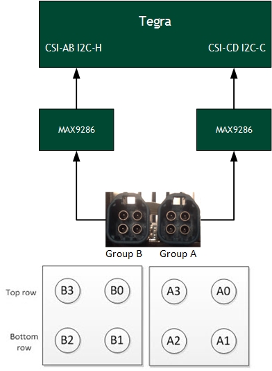
Mapping Connectors to Tegra
Each GMSL camera group can be routed to the Tegra chip using a GMSL deserializer.
Connecting Cameras to DRIVE PX 2 (P3407)
When you connect cameras to a specific camera group, you must attach the cameras in sequential order. For example, within Group A:
• Attach the first camera to A0.
• If used, attach the second camera to A1.
• If used, attach the second camera to A2.
• If used, attach the second camera to A3.
If you fail to attach cameras in this order, NvMedia generates an error message.
Homogeneous Camera Types
With the DRIVE PX 2 (P3407), homogeneous camera types are required per camera group.
• All cameras within a particular camera group must be of the same type.
• Each group can have a different type of camera.
For example, the cameras attached to group A must all be OV10640 or OV10635; they cannot be mixed.
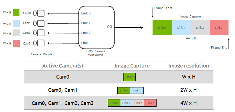
Default Aggregator Link Mapping
The following diagram shows how the digitized camera pictures are aggregated into a frame, where the image from the first camera appears first in the frame and the image from the last camera appears last in the frame. The frame size changes depending on how many cameras are connected.
All the sample applications that process images provide a ‑‑aggregate <n> option to specify the number of aggregated images in the frame. In this option, <n> maps as follows:
• n=1 maps to link0
• n=2 maps to link0 and link1 etc.
• n=4 maps to all links
The number of cameras connected must match the number specified in the
--aggregate option.
For guidance on extracting camera images from frames, see the
NvMedia Image Processing Sample Application.
MAXIM GMSL (Optional)
MAXIM Gigabit Multimedia Serial Link (GMSL) provides a compression-free alternative to Ethernet that is faster and more reliable than Ethernet. With this option you use MAX9271 on the camera and MAX9286 on DRIVE PX 2 AutoCruise. It provides these features:
• Can drive a cable length of ~15 m
• Provides Forward channel (video data) and Back channel (control data)
• Synchronizes multiple cameras
• Delivers Power over Coax (PoC)
• Provides diagnostics for failure
Mapping Connectors to Tegra Chip
Each GMSL camera group can be routed to the Tegra chip using a GMSL deserializer.
Camera Power Control
The NvMedia camera applications can use a SPI-based Control Communication protocol to request camera power on/off at the AURIX processors. It is not necessary to manually turn the camera power on/off through the AURIX console interface.
Prerequisites
• Ensure that the SPI-based communication used for camera power control is configured correctly.
To enable camera applications to use SPI-based control communication
1. Start camera capture at Tegra, using commands as described in the appropriate sample application in the
NvMedia Sample Applications.
For example, Continental OV10640 camera connected to A0 port, and an HDMI monitor connected to HDMI port.
2. From the Tegra Ubuntu 16.04 desktop, launch a terminal window and navigate to the following directory.
cd /home/nvidia/drive-t186ref-linux/samples/nvmedia/ipp_raw
3. Enter the following command.
./x11/nvmipp_raw -cf drive-px2-autocruise.conf -c dvp-svc210-raw12-1280x1080-ab -d 0 --nvplugin
Where:
• drive-px2-autocruise.conf specifies all the parameters for your configuration.
• dvp-svc210-raw12-1280x1080-ab specifies the capture-name parameter as defined in the configuration file for the Conti OV10640 camera connected to connector A0.
• 0 specifies the display number.
4. To obtain the available display devices for Tegra, run the following command:
nvmipp_raw -h
The available display devices are identified.
5. Select the desired display ID. --nvplugin is the NVMedia IPP plugin for the control algorithm components.