Setting Up DRIVE PX 2 AutoCruise (P3407)
This topic describes how to set up the NVIDIA DRIVE™ PX 2 AutoCruise platform.
Hardware Connectors
Consult the following images to identify the DRIVE PX 2 AutoCruise connectors.
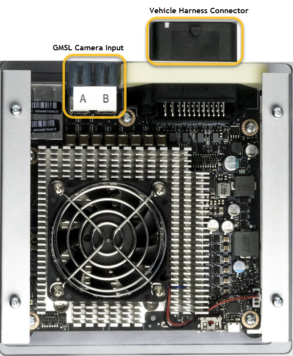
Top View
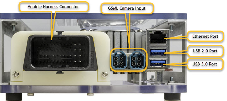
Front View
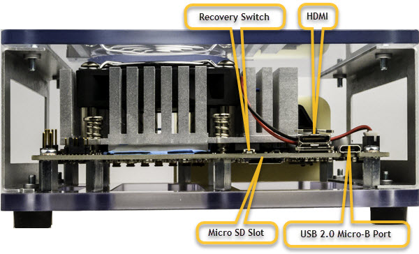
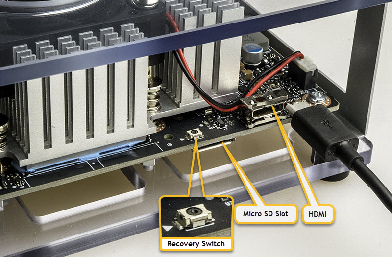
Back View
The HDMI port is a mini-HDMI port.
Recovery Switch
The HDMI is a mini-HDMI port.
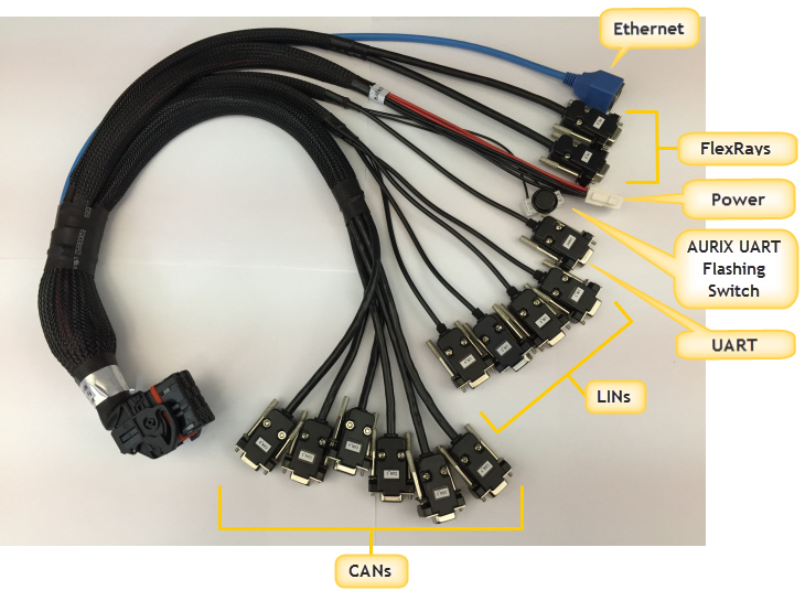
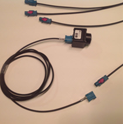
Vehicle Harness
The vehicle harness provides the following connections:
The Ethernet on the harness is BroadR-Reach and requires the included RJ45 to Molex connector.
Warning: | Before connecting the system, ensure that the DRIVE PX 2 is not connected to the AC power supply. Failure to do so may result in damage to the DRIVE PX 2. |
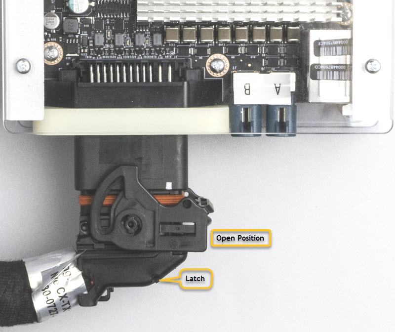
Connecting the Vehicle Harness
The following steps describe how to connect the vehicle harness to the Drive PX 2 connector.
To connect the DRIVE PX 2 to the harness
1. Verify that the switch on the vehicle harness cable is in the open position.
2. Connect the cable to the vehicle harness connector.
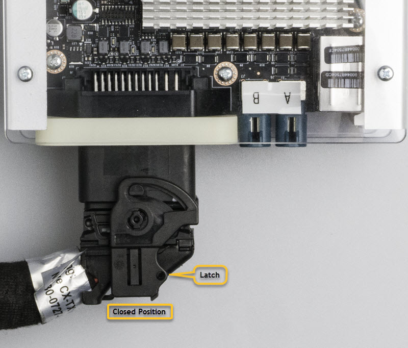
3. If the switch is in the closed position, press the latch and turn the switch to the open position.
4. Lock the harness by placing the switch into the closed position.
Follow the instructions in
Powering on the Device topic.
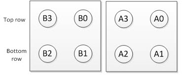
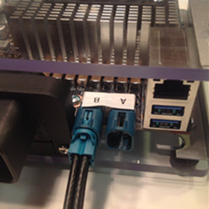
Connecting the Camera
The following steps describe how to connect a GMSL camera, for example OV10640, to DRIVE PX 2 AutoCruise at Port A0.
To connect the DRIVE PX2 to a camera
The mapping of the camera input connectors is as follows:
1. Connect the Coax cable to DRIVE PX 2 Group A connector.
2. Connect the camera to the Coax cable, for example OV10640, to the DRIVE PX 2 at PortA0.
Warning: | • The GMSL camera must be 8V tolerant. Refer to the NVIDIA DRIVE PX 2 Datasheet for details on the electrical requirements for the GMSL camera. • Always turn off main power before connecting or disconnecting cameras from NVIDIA DRIVE PX 2. • If the number of cameras is less than 4 and one fills either of the camera groups (A or B; they are independent of each other) not in the order of lower indices, then you must remap and enable cameras with the NvMedia --csi-outmap and --cam_enable options. |
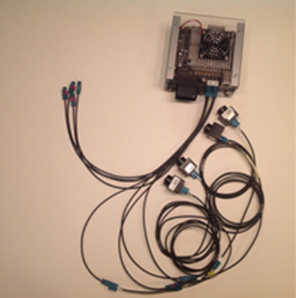
3. Connect subsequent camera to the next port in the group.
Your setup should look similar to the following:
Connecting the HDMI Display
Connect the HDMI display as follows:
1. Use a HDMI to mini-HDMI adaptor or cable to connect to the mini-HDMI port.
Consult the DRIVE PX 2 platform
Top View and
Front View to locate the Tegra mini-HDMI ports.
2. Connect the other end of the HDMI cable to the display monitor.
Connecting to the Network
DRIVE PX 2 contains network interfaces to provide the network connection for the Tegra chip. Consult the DRIVE PX 2
Front View to locate the required connectors.
There two Ethernet ports:
• Ethernet port on the board is a 1000/100/10 Base T port from the Tegra device for connecting to an ethernet LAN/WAN port with a standard CAT5/6 ethernet cable
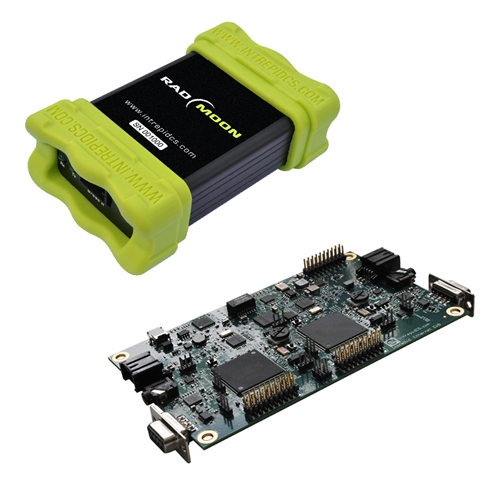
• The BroadR-Reach port on the harness is from the AURIX device for connecting (via the adaptor cable) to a BroadR-Reach to Ethernet adaptor box, such as Rad-Moon.
Consult the DRIVE PX 2
Back View and the harness cable image to locate the required connectors.
1. Connect the Ethernet cable at the Ethernet interface on DRIVE PX 2 to a wall socket or a router that has an internet connection.