Image Camera Capture (nvmimg_cap)
The NvMedia Image Camera Capture sample application nvmimg_cap demonstrates how to use the NvMedia Image Sensor Control API to capture frames from the sensors and display them to a screen or save them to a file.
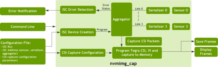
The nvmimg_cap sample application captures frames from sensors using the NvMedia Image Sensor Control API to display them to a screen and/or save them to a file. It can also be used to test the error detection functionality of the ISC.
The application requires users to provide command line input as well as a group of settings as defined in the configuration file.
The configuration file contains two sets of information.
• I2C bus and the device address to program sensor, serializer and the aggregator camera module.
• CSI capture configurations used to program the Tegra CSI and Video Input (VI) modules.
The CSI packets from the aggregator reach the Video Input (VI) module and saved to memory. The frames can be displayed using the Display Controller (DC) and/or saved to a file. Any random errors, such as camera power failure, or broken video links, during the ongoing capture process are detected by the aggregator device. The aggregator forwards this error condition using GPIO interrupt to this application to inform the user.
Image Sensor Control
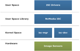
The Image Sensor Control feature allows the usage of the ISC framework to program the camera module. Image Sensor Control consists of three parts:
• The ISC kernel driver running on Linux kernes isc-mgr, isc-dev
• The user space library NVMedia IS
• The ISC driver in the user space
The ISC kernel driver, running on Linux OS, controls the power of the camera sensors through GPIOs, to:
• Report the error from GPIO interrupt
• Manage I2C communication
Error Detection
The Image Capture tool can be used to verify the error detection capability of ISC. The tool detects errors from the aggregator device for various scenarios such as camera power failure, video link failure, serializer failure etc.
In any of these cases, the aggregator device catches the error scenario since there is no data activity present on the lines there by detecting link error. The error is propagated to the application in the form of a GPIO interrupt and the application can take any necessary action. The action may include, but not limited to, reading the status register of the aggregator to figure out whether camera, serializer or GMSL link caused the failure. When an error is detected, the user receives a message similar to the following:
./nvmimg_cap -cf drive-px2-a.conf -c dvp-svc210-raw12-1280x1080-ab --aggregate 4
nvmedia: ERROR: ConfigISC_m_get_error:No Link error detected
Type "h" for a list of options
-nvmedia: ERROR: ExecuteNextCommand: Failed to read command
-nvmedia: ERROR: ConfigISC_m_get_error: No data activity on link 0
nvmedia: ERROR: ConfigISC_m_get_error: No data activity on link 1
TVMRCaptureGetErrorStatus: uncompleted frame
NvMediaICPGetFrame: dev get frame yuv failed (error 3)
nvmedia: ERROR: CaptureThreadFunc: NvMediaICPGetFrame failed
TVMRCaptureGetErrorStatus: uncompleted frame
NvMediaICPGetFrame: dev get frame yuv failed (error 3)
nvmedia: ERROR: CaptureThreadFunc: NvMediaICPGetFrame failed
NvMediaICPFeedFrame: buffers array is full. Reached timeout.
nvmedia: ERROR: CaptureThreadFunc: 115: NvMediaICPFeedFrame failed
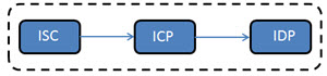
Camera Capture Pipeline
The Camera Capture pipeline consists of three components:
• Image Sensor Control (ISC): calibrates the camera sensors to provide the images. It is used for controlling the sensor such as setting the exposure and the white balance information. The initial configuration of the aggregators, serializers, and sensors are performed by the client application. The client application must:
• Create handles for the root, aggregator, serializer and sensor devices.
• Perform the initialization.
• Pass these handles to the sensor control component at component creation.
• Image Capture Processing (ICP): captures the frames coming from the CSI interface. It can capture an individual image coming from a camera, or aggregated images coming from multiple cameras. The output of this component provides the captured images.
• Image Display Processing (IDP): displays the YUV and RGB formatted images. It provides mechanisms to render YUV and RGBA surfaces on the display.
The following figure outlines the Camera Capture pipeline.
Code Flow
The following is the flow of the code for the camera capture components:
uint32_t addressList[1] = {0};
// Create ISC root device
iscRootDevice = NvMediaISCRootDeviceCreate(
ISC_ROOT_DEVICE_CFG(csiLink, i2cPort));
// Create aggregator device
addressList[0] = aggregatorDeviceAddress;
iscAggregatorDevice = NvMediaISCDeviceCreate(iscRootDevice,
addressList,
1,
GetAggregatorDriver(),
NULL);
// Create serializer devices
for(i = 0; i < TOTAL_DEVICES; i++)
{
addressList[0] = serializerDeviceAddress[i];
iscSerializerDevice[i] = NvMediaISCDeviceCreate(iscRootDevice,
addressList,
1,
GetSerializerDriver(),
NULL);
}
// Create sensor devices
for(i = 0; i < TOTAL_DEVICES; i++)
{
addressList[0] = sensorDeviceAddress[i];
iscSensorDevice[i] = NvMediaISCDeviceCreate(iscRootDevice,
addressList,
1,
GetSensorDriver(),
NULL);
}
// Program ISC Devices
ProgramISCDevices();
// Use ISC devices
...
// When application prepares to quit,
// Destroy sensor and serializer devices
for(i = 0; i < TOTAL_DEVICES; i++) {
if(iscSerializerDevice[i])
NvMediaISCDeviceDestroy(iscSerializerDevice[i]);
if(iscSensorDevice[i])
NvMediaISCDeviceDestroy(iscSensorDevice[i]);
}
// Destroy aggregator
if(iscAggregatorDevice)
NvMediaISCDeviceDestroy(iscAggregatorDevice);
// Destroy ISC root device
if(isc->iscRootDevice)
NvMediaISCRootDeviceDestroy(isc->iscRootDevice);
ICP:
// Create ICP
icpCapture = NvMediaICPCreateEx(NVMEDIA_IMAGE_CAPTURE_INTERFACE_FORMAT_CSI,
ICP_CAPTURE_FRAME_BUFS,
captureSettings);
// Feed frame
NvMediaICPFeedFrame(icpCapture,
captureBuffer->image,
FEED_FRAME_TIMEOUT);
// Loop until exit
while(!quit)
{
// Feed frame
NvMediaICPFeedFrameEx(icpCapture,
captureBuffer->image,
FEED_FRAME_TIMEOUT);
// Get captured frame
capturedFrame = NvMediaICPGetFrameEx(icpCapture,
GET_FRAME_TIMEOUT);
// Put image onto output queue
PutImageOnQueue();
}
// Get extra frame that was fed before the loop and release it
capturedFrame = NvMediaICPGetFrameEx(icpCapture,
GET_FRAME_TIMEOUT);
ReleaseImage(capturedFrame);
// Destroy ICP
NvMediaICPDestroyEx(icpCapture);
IDP:
// Create display
display = NvMediaIDPCreate(displayId,
windowId,
NULL,
isEnabled);
while(!quit)
{
// Get image from output queue
outputImage = GetImageFromQueue();
// Display image
status = NvMediaIDPFlip(display,
outputImage,
srcRect,
dstRect,
releaseList,
timeStamp);
// Release Images from releaseList
while(releaseList) {
ReleaseImage(*releaseList);
releaseList++;
}
}
// Destroy IDP
NvMediaIDPDestroy(display);
Command Line Usage
To run the Image Camera Capture sample application, run the following command:
$./nvmimg_cap -cf <config filename> -c <config setname> [options]
To quit the application, enter q at the command line.
The configuration file format and the configuration file set format are defined as follows:
Option | Parameter | Description | Defaults |
-f | <file prefix> | Saves captured frames to a file. Each file starts with the specified prefix concatenated with any calibration parameters and the frame index. | Default: Frames are not saved to file(s) |
-h | N/A | Prints the usage syntax. | N/A |
--ext_sync | [duty_ratio] | Enables external synchronization. (AR0231 or OV10635 sensors only.) | 0.25 |
-v | [level] | Logging Level 0 Errors 1 Warnings 2 Information 3 Debug If the option is not provided, uses 0 Errors. | Default: 0
If option is used, but level is not provided, default: 3 |
-d | [id] | Enables the display. If provided, uses the display with the specified ID. | Default: Display is disabled.
If ID is not provided, the sample uses the first display available. |
-w | <id> | Uses the window with the specified ID for display. | Default: 0 |
-z | <depth> | Specifies the depth for the display. | Default: 0 |
-cf | [filename] | Specifies the configuration file. Co-locate the file with nvmimg_cap. | N/A |
-c | [name] | Specifies the parameters set name. | N/A |
-p | <x:y:w:h> | Specifies the window position rectangle. | Default: No positioning |
-lc | N/A | Lists the available configuration sets. | N/A |
-t | N/A | Specifies TPG Mode. Skips sensor initialization. | N/A |
-n | [frames] | Number of frames to capture and quit automatically | N/A |
--aggregate | [n] | Creates an aggregated image from the captured frame of the size: (W*n)*H. | N/A |
--cam_enable | <0001 to 1111> | Enables or disables the camera, where each bit represents a camera in the [3210] order. In other words, the left-most bit represents camera 3 and the right-most bit, camera 0. Bit settings for each camera are: Enable: 1 Disable: 0
Video is not available from the disabled camera.
| Default: 0001 |
--cam_mask | <0000 to 1110> | Masks or unmasks the cameras, where each bit represents a camera in the [3210] order. You cannot mask all cameras, which means that 1111 is not allowed. Bit settings for each camera are: Mask:1 Unmask:0 | Default: 0000 |
--csi_outmap | <abcd> | Sets the CSI out order for the cameras. The a, b, c, d order can be 0, 1, 2, or 3 in any order. Each number must only be used once. | Default: 3210 |
--slave | N/A | Specifies that the application is running with a slave aggregator. | |
--vc_enable | N/A | Enable virtual channels for capturing the frames. | N/A |
Configuration File Parameters
The configuration file contains groups of settings that configure capture settings. The application parses and selects a group of settings using the provided configuration set name as specified in the command line.
Each configuration set begins with a capture-params-set number, followed by the configuration parameters.
Valid configuration parameters are as follows:
Parameter | Description | Valid Value/Example |
capture-name | Captures the set name. | Any string. |
capture-description | Provides a description of the type of sensor being used for the capture. | Any string. |
input_device | Specifies the name of the capture image device. | "ref_max9286_9271_ov10635", "ref_max9286_9271_ov10640", "ref_max9286_96705_ar0231" |
input_format | Specifies the capture format of the sensor. | "422p", "raw12", "raw16log", |
surface_format | Specifies the CSI surface format. | "yv16", "rgb", "raw8", "raw10", "raw12" |
resolution | Specifies the input resolution. | "<width>x<height>" |
csi_lanes | Specifies the CSI interface lanes. | 1, 2, 4 |
interface | Specifies the capture interface. | "csi-a", "csi-b", "csi-c", "csi-d", "csi-e", "csi-f", "csi-ab", "csi-cd", "csi-ef" |
embedded_lines_top | Specifies the number of extra top lines for the CSI capture. | Unsigned integer. Example: 2 |
embedded_lines_bottom | Specifies the number of extra bottom lines for the CSI capture. | Unsigned integer. Example: 2 |
i2c_device | Specifies the I2C device to use for configuring the CSI device. | 0: NVMEDIA_ISC_I2C_PORT_A
1: NVMEDIA_ISC_I2C_PORT_B,
2: NVMEDIA_ISC_I2C_PORT_C,
3: NVMEDIA_ISC_I2C_PORT_D |
max9271_address | Specifies the address of the serializer device. | 0x40: P2360, E1859 |
max9271_address_0 | Specifies the virtual address of serializer 0. | Example: 0x41 |
max9271_address_1 | Specifies the virtual address of serializer 1. | Example: 0x42 |
max9271_address_2 | Specifies the virtual address of serializer 2. | Example: 0x43 |
max9271_address_3 | Specifies the virtual address of serializer 3. | Example: 0x44 |
max9286_address | Specifies the address of the aggregator device. | 0x6a: E1859 + CSI-AB,
0x6c: E1859 + CSI-CD,
0x48: P2360 + CSI-AB,
0x4A: P2360 + CSI-CD |
sensor_address | Specifies the address of the sensor device. | 0x30: OV10635; 0x30: OV10640; 0x10: AR0231 |
sensor_address_0 | Specifies the virtual address of sensor 0. | Example: 0x31 |
sensor_address_1 | Specifies the virtual address of sensor 1. | Example: 0x32 |
sensor_address_2 | Specifies the virtual address of sensor 2. | Example: 0x33 |
sensor_address_3 | Specifies the virtual address of sensor 4. | Example: 0x34 |
Configuration Set
Each configuration set requires mandatory parameters to determine the capture environment. The required parameters are as follows:
capture-name = "<set name>"
capture-description = "<description>"
input_device = "<input device>"
input_format = "<input format>"
surface_format = "<surface format>"
resolution = "<resolution>"
csi_lanes = <csi lanes>
interface = "<interface>"
i2c_device = <i2c device>
max9271_address = <serializer address>
max9286_address = <aggregator address>
sensor_address = <sensor address>
Where:
• capture-name identifies the set of configuration parameters.
• capture-description describes the given configuration set.
• input_device specifies the type of sensor used to capture images.
• input_format specifies the format in which the sensor is capturing and transmitting images.
• surface_format specifies the CSI surface format.
• resolution specifies the resolution at which the sensor is capturing images.
• csi_lanes specifies the number of CSI lanes used.
• interface specifies the CSI interface used for the capture.
• i2c_device specifies the ID of the I2C device used to communicate with the aggregator, serializer and sensor.
• max9271_address specifies the I2C address of the serializer.
• max9286_address specifies the I2C address of the deserializer/aggregator.
• sensor_address specifies the address of the sensor used for I2C.
The optional parameters are as follows:
embedded_lines_top = <extra top lines>
embedded_lines_bottom = <extra bottom lines>
max9271_address_0 = <serializer 0 address>
max9271_address_1 = <serializer 1 address>
max9271_address_2 = <serializer 2 address>
max9271_address_3 = <serializer 3 address>
sensor_address_0 = <sensor 0 address>
sensor_address_1 = <sensor 1 address>
sensor_address_2 = <sensor 2 address>
sensor_address_3 = <sensor 3 address>
Where:
• embedded_lines_top specifies the number of embedded data lines found at the top of the frame. If not specified, a default value of 0 is assumed.
• embedded_lines_bottom specifies the number of embedded data lines found at the bottom of the frame. If not specified, a default value of 0 is assumed.
• max9271_address_(0/1/2/3) assigns a virtual I2C address to each of the serializers.
• sensor_address_(0/1/2/3) assigns a virtual I2C address to each of the sensors. The aggregator maps these addresses to the corresponding device.
The following provides an example configuration set for a Conti camera on the DRIVE PX platform:
[capture-params-set 7]
capture-name = "dvp-svc210-raw12-1280x1080-ab"
capture-description = "csi-dvp 1280x1080(raw12) 4-lane capture on interface:ab; I2C device 2"
board = "E2379-a00"
input_device = "c_max9286_9271_ov10640"
input_format = "raw12"
surface_format = "raw12"
resolution = "1280x1080"
csi_lanes = 4
interface = "csi-ab"
embedded_lines_top = 2
embedded_lines_bottom = 2
i2c_device = 2
max9286_address = 0x48
max9271_address = 0x40
sensor_address = 0x30
Comments
Comments begin with a pound sign (#). The text that appears after the pound sign to the end of the line is considered to be a comment and is not parsed by the script file parser.
Debugging Image Sensor Control
The Image Sensor Control kernel driver consists of ISC manager isc-mgr and ISC devices isc-dev.
• isc-mgr controls the power to the camera module and reports any error along the path.
• isc-dev is an i2c client device in Linux kernel. It sends I2C commands or receives I2C data. It can be created through isc-mgr or created through DT in the kernel.
To debug ISC, you must control the power of the camera and the register settings programmed into the camera sensor using isc-mgr and isc-dev in debugfs of the Linux directory. Camera power is controlled dynamically by all the NvMedia camera sample applications. This is an additional control that can be used for debugging.
Camera Power Control
To Power on the cameras on CSI-EF port
Echo the value to the isc-mgr from debugfs on the target.
echo <val> > /sys/kernel/debug/isc-mgr.1.e/pwr-on
To Power off the cameras on CSI-EF port
echo 1 > /sys/kernel/debug/isc-mgr.1.e/pwr-off
The <val> is determined from the Device Tree; which is platform specific. For example, on Drive PX, val=1 enables power on Links 0 and 1 while val=2 enables power on Link 2 and 3.
Camera Register Control
You can read and write any register of the camera module (sensor, serializer) and aggregator through the isc-devices associated with each one.
The following provides an example of writing 0x43 to the I2C offset address 0x04 on the serializer (with device address 0x40).
echo 0x04 > /sys/kernel/debug/isc-mgr.1.e/isc-dev.1.40/offset
echo 0x43 > /sys/kernel/debug/isc-mgr.1.e/isc-dev.1.40/val
Troubleshooting
The following issues are errors users of this application have encountered.
Issue 1: TVMRCaptureGetErrorStatus - No Frame Start
The error message is as follows:
./nvmimg_cap -cf drive-px2-a.conf -c dvp-svc210-raw12-1280x1080-ab -d 0 -w 1
Used display - Display Info - Enabled:1 displayId:0 type:B306 size:1920x1200 refresh:59.954842 type:HDMI
[ 548.335352] nvmap_pgprot: PID 377: nvmimg_cc: TAG: 0x1100 WARNING: NVMAP_HAN DLE_WRITE_COMBINE should be used in place of NVMAP_HANDLE_UNCACHEABLE on ARM64 Capturing Frames...
TVMRCaptureGetErrorStatus: no frame start
NvMediaICPGetFrame: dev get frame yuv failed (error 2)
nvmedia: ERROR: CaptureThreadFunc: NvMediaICPGetFrame failed [ 549.349909] vi vi: error notifier set to 1 [ 549.357866] vi vi: error notifier set to 1 [ 549.365458] vi vi: error notifier set to 1
TVMRCaptureGetErrorStatus: no frame start
NvMediaICPGetFrame: dev get frame yuv failed (error 2)
nvmedia: ERROR: CaptureThreadFunc: NvMediaICPGetFrame failed
nvmedia: ERROR: CaptureThreadFunc: BufferPool_AcquireBuffer failed 7
This capture error indicates that the start of CSI frame not available. The aggregator was unable to lock/synchronize the frames from the camera modules. This issue does not occur when reference cameras are being used. Check the aggregator settings for more information.
Issue 2: TVMRCaptureGetErrorStatus: CSI Packet Error
The error message is as follows:
./nvmimg_cap -cf drive-px2-a.conf -c dvp-ov10635-yuv422-1280x800-ef -d 0 -w 1
Capturing Frames...
TVMRCaptureGetErrorStatus: csi packet error
NvMediaICPGetFrame: dev get frame yuv failed (error 4)
nvmedia: ERROR: CaptureThreadFunc: NvMediaICPGetFrame failed
TVMRCaptureGetErrorStatus: csi packet error
NvMediaICPGetFrame: dev get frame yuv failed (error 4)
nvmedia: ERROR: CaptureThreadFunc: NvMediaICPGetFrame failed
nvmedia: ERROR: CaptureThreadFunc: BufferPool_AcquireBuffer failed 7
A generic CSI packet error occurred during the capture. Possible causes include:
1. Image resolution mismatch between the captured images from camera and expectation on the Tegra side.
2. .Image format (raw, yuv) mismatch between camera and Tegra side.
3. Noise/signal integrity for the CSI link between camera and Tegra.
Issue 3: Failed to setup the config link
The error message is as follows:
./nvmimg_cap -cf drive-px2-a.conf -c dvp-svc210-raw12-1280x1080-ab -d 1 -w 1
nvmedia: ERROR: setup_config_link: Failed to set aggregator defaults
nvmedia: ERROR: ConfigISC_m: Failed to setup config link
nvmedia: ERROR: ImgCapture_Init: Failed to create ISC devices
nvmedia: ERROR: ImgCapture_Init: Failed to initialize ImgCapture
nvmedia: ERROR: main: Failed to Initialize ImgCapture
Possible causes include:
2. Verify the aggregator address as specified in the configuration file. An incorrect address to program results in a failure.
3. Verify the aggregator is powered on. The GPIO value associated to power on the aggregator can be verified as follows:
echo 1 > /sys/kernel/debug/isc-mgr.<i2c bus>="">.<csi port>="">/pwr-on
Issue 4: Failed to configure video link - Can't detect config link (0)
The error message is as follows:
./nvmimg_cap -cf drive-px2-a.conf -c dvp-ov10635-yuv422-1280x800-ef -d 0 -w 1 --aggregate 4
Created display - Display Info - Enabled:1 displayId:0 type:B306 size:1920x1200 refresh:59.954842 type:HDMI
nvmedia: ERROR: configure_video_link: Can't detect config link(0)
nvmedia: ERROR: ConfigISC_m: Failed to setup video link
nvmedia: ERROR: ImgCapture_Init: Failed to create ISC devices
nvmedia: ERROR: ImgCapture_Init: Failed to initialize ImgCapture
nvmedia: ERROR: main: Failed to Initialize ImgCapture
Possible causes include:
1. The serializer or the camera sensor is not connected or powered on. Verify the connectivity and power for all components.
2. An incorrect serializer address is defined in the configuration file; or the serializer was configured incorrectly. Cross check the configuration parameters.
Issue 5: Failed to configure video link - Image sensor (0) device is not present
The error message is as follows:
./nvmimg_cap -cf drive-px2-a.conf -c dvp-ov10635-yuv422-1280x800-ab -d 0 -w 1
Created display - Display Info - Enabled:1 displayId:0 type:B306 size:1920x1200 refresh:59.954842 type:HDMI
nvmedia: ERROR: configure_video_link: Image sensor(0) device is not present
nvmedia: ERROR: ConfigISC_m: Failed to setup video link
nvmedia: ERROR: ImgCapture_Init: Failed to create ISC devices
nvmedia: ERROR: ImgCapture_Init: Failed to initialize ImgCapture
nvmedia: ERROR: main: Failed to Initialize ImgCapture
Possible causes include:
2. Verify that the sensor is programmed with a correct address.
Issue 6: Failed to configure video link - Video Link(0) is not detected
The error message is as follows:
./nvmimg_cap -cf drive-px2-a.conf -c dvp-ov10640-raw16log-1280x800-ab -d 1 -w 1
nvmedia: ERROR: ConfigISC_m: Video Link(0) is not detected
nvmedia: ERROR: ImgCapture_Init: Failed to create ISC devices
nvmedia: ERROR: ImgCapture_Init: Failed to initialize ImgCapture
nvmedia: ERROR: main: Failed to Initialize ImgCapture
This error occurs when an incorrect configuration is used to set up the camera sensor. For example, programming OV10640 sensor when OV10635 is actually connected to the platform.
Issue 7: Can't open the ISC manager
The error message is as follows:
./nvmimg_cap -cf drive-px2-a.conf -c dvp-ov10635-yuv422-1280x800-ab -d 1 -w 1
iscRootDevOpen: can't open /dev/isc-mgr.3.a - No such file or directory
NvMediaISCRootDeviceCreate: Unable to open root device
nvmedia: ERROR: ImageCapture_PowerOn: Failed to create NvMedia ISC root device
nvmedia: ERROR: ImageCapture_Init: Failed to power on
nvmedia: ERROR: ImageCapture_Init: Failed to initialize image capture
nvmedia: ERROR: main: Failed to initialize Test
This error occurs when an incorrect I2C device is used in the DTS file or the script file. Verify that the configuration present in the device tree, at the following location, matches that of the script:
cat <KERNEL_TOP>/arch/arm64/boot/dts/<platform.dtsi>
There is a specific I2C device associated with the given CSI port. This error occurs because an incorrect initialization has been made.
cat /dev/isc-mgr.<i2c dev>.<csi port>
i2c dev = <0,..6>
csi port = <a, c, e>
Issue 8: Failed to create Image Display
The error message is as follows:
./nvmimg_cap -cf drive-px2-a.conf -c dvp-ov10635-yuv422-1280x800-ab -d 1 -w 1
nvmedia: ERROR: ImageDisplayCreate: No display created
nvmedia: ERROR: ImageDisplayCreate: Failed to create ImageDisplay
nvmedia: ERROR: NvMTestDisplayCreate: No image display created
nvmedia: ERROR: NvMTestDisplayCreate: Failed to create NvMTestDisplay
nvmedia: ERROR: ImageCapture_Init: Failed to create ImageDisplay context
nvmedia: ERROR: ImageCapture_Init: Failed to initialize image capture
nvmedia: ERROR: main: Failed to initialize Test
The display device creation failed. A possible cause may be that an incorrect display ID is provided on the command line. The nvmimg_cap application automatically detects display ID. Run the application with -h option to identify the correct display ID.
./nvmimg_cap -h
Available command line options:
-h Print usage
-v [level] Logging Level. Default = 0
0: Errors, 1: Warnings, 2: Info, 3: Debug
Default: 0
-d [n] Set display ID
Available display devices (1)
Display ID : 0 (hdmi)
If multiple display devices are detected, -d option selects the first device, if ID is not specified. An error results if the display ID is unusable.
Issue 9: FlipQ Create Failed
The error message is as follows:
NvMediaIDPCreate: FlipQ create failed (display: 0 window: 0)
nvmedia: ERROR: ImageDisplayCreate: Failed to create NvMedia display
nvmedia: ERROR: ImageDisplayCreate: Failed to create ImageDisplay
nvmedia: ERROR: NvMTestDisplayCreate: No image display created
nvmedia: ERROR: NvMTestDisplayCreate: Failed to create NvMTestDisplay
nvmedia: ERROR: Capture_Init: Failed to create test display
nvmedia: ERROR: Capture_Init: Failed to initialize ImgCapture
nvmedia: ERROR: main: Failed to Initialize ImgCapture
Each display ID and window ID combination yields a unique NvMedia output surface. This error occurs if this combination is being used by any other application. Verify the target to check if any other application is using the current output surface combination.
Example Commands
The following examples represent commonly used commands.
To capture RAW12 frames from the sensor (AR0231) and display them on to the screen on the CSI port AB:
./nvmimg_cap -cf drive-px2-a.conf -c dvp-ar0231-raw12-1920x1208-ab -d 0 -w 1
To capture YUV422 frames from 4 sensors (OV10635), store them to a file with the prefix "frame" (files are named frame_0.raw, frame_1.raw, etc.), and display onto the screen on the CSI port AB:
./nvmimg_cap -cf drive-px2-a.conf -c dvp-ov10635-yuv422-1280x800-ab -d 0 -w 1 -f frame --aggregate 4
For the DRIVE PX platform, the above command is executed either on Tegra A or Tegra B. However, Drive PX platform routes the images to both Tegras at the same time. To exercise this feature, use the slave option on one of the Tegras so that only one of the Tegras controls the camera sensor programming.
./nvmimg_cap -cf drive-px2-b.conf -c dvp-ov10635-yuv422-1280x800-ab -d 0 -w 1 -f frame --aggregate 4 --slave
The slave option on the command line allows Tegra to capture the images from the sensors that are already programmed by the master Tegra. Thereby the slave Tegra programs only the aggregator.
To capture RAW12 frames from the sensor (OV10640) and display on to the screen on the CSI port AB:
./nvmimg_cap -cf drive-px2-a.conf -c dvp-svc210-raw12-1280x1080-ab -d 0 -w 1
For camera remapping, the csi_outmap of the enabled camera link(s) must start with 0, then 1, 2, and 3. The disabled camera cannot be assigned a smaller out number than the enabled camera.
To capture YUV422 frames from 3 cameras (OV10635):
• Disable camera 2.
• Mask camera 0.
• Adjust the CSI output order.
• Set the display onto the screen on the CSI port AB.
In this case, the csi_outmap cannot be set to 1203. For example:
./nvmimg_cap -cf drive-px2-a.conf -c dvp-ov10635-yuv422-1280x800-ab -d 0 -w 1 --cam_enable 1011 --cam_mask 0001 --csi_outmap 1302
Parameter Mapping for DRIVE PX 2 (P3407)
Camera Group | Camera | Number of Cameras | Command Set |
A | OV10635 | 1 | ./nvmimg_cap -cf drive-px2-autocruise.conf -c dvp-ov10635-yuv422-1280x800-ab -d 0 --aggregate 1 |
4 | ./nvmimg_cap -cf drive-px2-autocruise.conf -c dvp-ov10635-yuv422-1280x800-ab -d 0 --aggregate 4 |
Maxim OV10640 | 1 | ./nvmimg_cap -cf drive-px2-autocruise.conf -c dvp-ov10640-raw12-1280x1080-ab -d 0 --aggregate 1 |
4 | ./nvmimg_cap -cf drive-px2-autocruise.conf -c dvp-ov10640-raw12-1280x1080-ab -d 0 --aggregate 4 |
Continental OV10640 | 1 | ./nvmimg_cap -cf drive-px2-autocruise.conf -c dvp-svc210-raw12-1280x1080-ab -d 0 --aggregate 1 |
4 | ./nvmimg_cap -cf drive-px2-autocruise.conf -c dvp-svc210-raw12-1280x1080-ab -d 0 --aggregate 4 |
AR0231 | 1 | ./nvmimg_cap -cf drive-px2-autocruise.conf -c dvp-ar0231-raw12-1920x1208-ab -d 0 --aggregate 1 |
4 | ./nvmimg_cap -cf drive-px2-autocruise.conf -c dvp-ar0231-raw12-1920x1208-ab -d 0 --aggregate 4 |
AR0231 RCCB | 1 | ./nvmimg_cap -cf drive-px2-autocruise.conf -c dvp-ar0231-rccb-raw12-1920x1208-ab -d 0 --aggregate 1 |
4 | ./nvmimg_cap -cf drive-px2-autocruise.conf -c dvp-ar0231-rccb-raw12-1920x1208-ab -d 0 --aggregate 4 |
B | OV10635 | 1 | ./nvmimg_cap -cf drive-px2-autocruise.conf -c dvp-ov10635-yuv422-1280x800-cd -d 0 --aggregate 1 |
4 | ./nvmimg_cap -cf drive-px2-autocruise.conf -c dvp-ov10635-yuv422-1280x800-cd -d 0 --aggregate 4 |
Maxim OV10640 | 1 | ./nvmimg_cap -cf drive-px2-autocruise.conf -c dvp-ov10640-raw12-1280x1080-cd -d 0 --aggregate 1 |
4 | ./nvmimg_cap -cf drive-px2-autocruise.conf -c dvp-ov10640-raw12-1280x1080-cd -d 0 --aggregate 4 |
Continental OV10640 | 1 | ./nvmimg_cap -cf drive-px2-autocruise.conf -c dvp-svc210-raw12-1280x1080-cd -d 0 --aggregate 1 |
4 | ./nvmimg_cap -cf drive-px2-autocruise.conf -c dvp-svc210-raw12-1280x1080-cd -d 0 --aggregate 4 |
AR0231 | 1 | ./nvmimg_cap -cf drive-px2-autocruise.conf -c dvp-ar0231-raw12-1920x1208-cd -d 0 --aggregate 1 |
4 | ./nvmimg_cap -cf drive-px2-autocruise.conf -c dvp-ar0231-raw12-1920x1208-cd -d 0 --aggregate 4 |
AR0231 RCCB | 1 | ./nvmimg_cap -cf drive-px2-autocruise.conf -c dvp-ar0231-rccb-raw12-1920x1208-cd -d 0 --aggregate 1 |
4 | ./nvmimg_cap -cf drive-px2-autocruise.conf -c dvp-ar0231-rccb-raw12-1920x1208-cd -d 0 --aggregate 4 |
Parameter Mapping for DRIVE PX 2 (P2379) on Tegra A
Camera Group | Camera | Number of Cameras | Command Set |
A | OV10635 | 1 | ./nvmimg_cap -cf drive-px2-a.conf -c dvp-ov10635-yuv422-1280x800-ab -d 0 --aggregate 1 |
4 | ./nvmimg_cap -cf drive-px2-a.conf -c dvp-ov10635-yuv422-1280x800-ab -d 0 --aggregate 4 |
Maxim OV10640 | 1 | ./nvmimg_cap -cf drive-px2-a.conf -c dvp-ov10640-raw12-1280x1080-ab -d 0 --aggregate 1 |
4 | ./nvmimg_cap -cf drive-px2-a.conf -c dvp-ov10640-raw12-1280x1080-ab -d 0 --aggregate 4 |
Continental OV10640 | 1 | ./nvmimg_cap -cf drive-px2-autocruise.conf -c dvp-svc210-raw12-1280x1080-ab -d 0 --aggregate 1 |
4 | ./nvmimg_cap -cf drive-px2-autocruise.conf -c dvp-svc210-raw12-1280x1080-ab -d 0 --aggregate 4 |
AR0231 | 1 | ./nvmimg_cap -cf drive-px2-a.conf -c dvp-ar0231-raw12-1920x1208-ab -d 0 --aggregate 1 |
4 | ./nvmimg_cap -cf drive-px2-a.conf -c dvp-ar0231-raw12-1920x1208-ab -d 0 --aggregate 4 |
AR0231 RCCB | 1 | ./nvmimg_cap -cf drive-px2-a.conf -c dvp-ar0231-rccb-raw12-1920x1208-ab -d 0 --aggregate 1 |
4 | ./nvmimg_cap -cf drive-px2-a.conf -c dvp-ar0231-rccb-raw12-1920x1208-ab -d 0 --aggregate 4 |
B | OV10635 | 1 | ./nvmimg_cap -cf drive-px2-a.conf -c dvp-ov10635-yuv422-1280x800-cd -d 0 --aggregate 1 |
4 | ./nvmimg_cap -cf drive-px2-a.conf -c dvp-ov10635-yuv422-1280x800-cd -d 0 --aggregate 4 |
Maxim OV10640 | 1 | ./nvmimg_cap -cf drive-px2-a.conf -c dvp-ov10640-raw12-1280x1080-cd -d 0 --aggregate 1 |
4 | ./nvmimg_cap -cf drive-px2-a.conf -c dvp-ov10640-raw12-1280x1080-cd -d 0 --aggregate 4 |
Continental OV10640 | 1 | ./nvmimg_cap -cf drive-px2-autocruise.conf -c dvp-svc210-raw12-1280x1080-cd -d 0 --aggregate 1 |
4 | ./nvmimg_cap -cf drive-px2-autocruise.conf -c dvp-svc210-raw12-1280x1080-cd -d 0 --aggregate 4 |
AR0231 | 1 | ./nvmimg_cap -cf drive-px2-a.conf -c dvp-ar0231-raw12-1920x1208-cd -d 0 --aggregate 1 |
4 | ./nvmimg_cap -cf drive-px2-a.conf -c dvp-ar0231-raw12-1920x1208-cd -d 0 --aggregate 4 |
AR0231 RCCB | 1 | ./nvmimg_cap -cf drive-px2-a.conf -c dvp-ar0231-rccb-raw12-1920x1208-cd -d 0 --aggregate 1 |
4 | ./nvmimg_cap -cf drive-px2-a.conf -c dvp-ar0231-rccb-raw12-1920x1208-cd -d 0 --aggregate 4 |
C | OV10635 | 1 | ./nvmimg_cap -cf drive-px2-a.conf -c dvp-ov10635-yuv422-1280x800-ef -d 0 --aggregate 1 |
4 | ./nvmimg_cap -cf drive-px2-a.conf -c dvp-ov10635-yuv422-1280x800-ef -d 0 --aggregate 4 |
Maxim OV10640 | 1 | ./nvmimg_cap -cf drive-px2-a.conf -c dvp-ov10640-raw12-1280x1080-ef -d 0 --aggregate 1 |
4 | ./nvmimg_cap -cf drive-px2-a.conf -c dvp-ov10640-raw12-1280x1080-ef -d 0 --aggregate 4 |
Continental OV10640 | 1 | ./nvmimg_cap -cf drive-px2-autocruise.conf -c dvp-svc210-raw12-1280x1080-ef -d 0 --aggregate 1 |
4 | ./nvmimg_cap -cf drive-px2-autocruise.conf -c dvp-svc210-raw12-1280x1080-ef -d 0 --aggregate 4 |
AR0231 | 1 | ./nvmimg_cap -cf drive-px2-a.conf -c dvp-ar0231-raw12-1920x1208-ef -d 0 --aggregate 1 |
4 | ./nvmimg_cap -cf drive-px2-a.conf -c dvp-ar0231-raw12-1920x1208-ef -d 0 --aggregate 4 |
AR0231 RCCB | 1 | ./nvmimg_cap -cf drive-px2-a.conf -c dvp-ar0231-rccb-raw12-1920x1208-ef -d 0 --aggregate 1 |
4 | ./nvmimg_cap -cf drive-px2-a.conf -c dvp-ar0231-rccb-raw12-1920x1208-ef -d 0 --aggregate 4 |
Parameter Mapping for DRIVE PX 2 (P2379) on Tegra B
Camera Group | Camera | Number of Cameras | Command Set |
A | OV10635 | 1 | ./nvmimg_cap -cf drive-px2-b.conf -c dvp-ov10635-yuv422-1280x800-ab -d 0 --aggregate 1 |
4 | ./nvmimg_cap -cf drive-px2-b.conf -c dvp-ov10635-yuv422-1280x800-ab -d 0 --aggregate 4 |
Maxim OV10640 | 1 | ./nvmimg_cap -cf drive-px2-b.conf -c dvp-ov10640-raw12-1280x1080-ab -d 0 --aggregate 1 |
4 | ./nvmimg_cap -cf drive-px2-b.conf -c dvp-ov10640-raw12-1280x1080-ab -d 0 --aggregate 4 |
Continental OV10640 | 1 | ./nvmimg_cap -cf drive-px2-autocruise.conf -c dvp-svc210-raw12-1280x1080-ab -d 0 --aggregate 1 |
4 | ./nvmimg_cap -cf drive-px2-autocruise.conf -c dvp-svc210-raw12-1280x1080-ab -d 0 --aggregate 4 |
AR0231 | 1 | ./nvmimg_cap -cf drive-px2-b.conf -c dvp-ar0231-raw12-1920x1208-ab -d 0 --aggregate 1 |
4 | ./nvmimg_cap -cf drive-px2-b.conf -c dvp-ar0231-raw12-1920x1208-ab -d 0 --aggregate 4 |
AR0231 RCCB | 1 | ./nvmimg_cap -cf drive-px2-b.conf -c dvp-ar0231-rccb-raw12-1920x1208-ab -d 0 --aggregate 1 |
4 | ./nvmimg_cap -cf drive-px2-b.conf -c dvp-ar0231-rccb-raw12-1920x1208-ab -d 0 --aggregate 4 |
B | OV10635 | 1 | ./nvmimg_cap -cf drive-px2-b.conf -c dvp-ov10635-yuv422-1280x800-cd -d 0 --aggregate 1 |
4 | ./nvmimg_cap -cf drive-px2-b.conf -c dvp-ov10635-yuv422-1280x800-cd -d 0 --aggregate 4 |
Maxim OV10640 | 1 | ./nvmimg_cap -cf drive-px2-b.conf -c dvp-ov10640-raw12-1280x1080-cd -d 0 --aggregate 1 |
4 | ./nvmimg_cap -cf drive-px2-b.conf -c dvp-ov10640-raw12-1280x1080-cd -d 0 --aggregate 4 |
Continental OV10640 | 1 | ./nvmimg_cap -cf drive-px2-autocruise.conf -c dvp-svc210-raw12-1280x1080-cd -d 0 --aggregate 1 |
4 | ./nvmimg_cap -cf drive-px2-autocruise.conf -c dvp-svc210-raw12-1280x1080-cd -d 0 --aggregate 4 |
AR0231 | 1 | ./nvmimg_cap -cf drive-px2-b.conf -c dvp-ar0231-raw12-1920x1208-cd -d 0 --aggregate 1 |
4 | ./nvmimg_cap -cf drive-px2-b.conf -c dvp-ar0231-raw12-1920x1208-cd -d 0 --aggregate 4 |
AR0231 RCCB | 1 | ./nvmimg_cap -cf drive-px2-b.conf -c dvp-ar0231-rccb-raw12-1920x1208-cd -d 0 --aggregate 1 |
4 | ./nvmimg_cap -cf drive-px2-b.conf -c dvp-ar0231-rccb-raw12-1920x1208-cd -d 0 --aggregate 4 |
C | OV10635 | 1 | ./nvmimg_cap -cf drive-px2-b.conf -c dvp-ov10635-yuv422-1280x800-ef -d 0 --aggregate 1 |
4 | ./nvmimg_cap -cf drive-px2-b.conf -c dvp-ov10635-yuv422-1280x800-ef -d 0 --aggregate 4 |
Maxim OV10640 | 1 | ./nvmimg_cap -cf drive-px2-b.conf -c dvp-ov10640-raw12-1280x1080-ef -d 0 --aggregate 1 |
4 | ./nvmimg_cap -cf drive-px2-b.conf -c dvp-ov10640-raw12-1280x1080-ef -d 0 --aggregate 4 |
Continental OV10640 | 1 | ./nvmimg_cap -cf drive-px2-autocruise.conf -c dvp-svc210-raw12-1280x1080-ef -d 0 --aggregate 1 |
4 | ./nvmimg_cap -cf drive-px2-autocruise.conf -c dvp-svc210-raw12-1280x1080-ef -d 0 --aggregate 4 |
AR0231 | 1 | ./nvmimg_cap -cf drive-px2-b.conf -c dvp-ar0231-raw12-1920x1208-ef -d 0 --aggregate 1 |
4 | ./nvmimg_cap -cf drive-px2-b.conf -c dvp-ar0231-raw12-1920x1208-ef -d 0 --aggregate 4 |
AR0231 RCCB | 1 | ./nvmimg_cap -cf drive-px2-b.conf -c dvp-ar0231-rccb-raw12-1920x1208-ef -d 0 --aggregate 1 |
4 | ./nvmimg_cap -cf drive-px2-b.conf -c dvp-ar0231-rccb-raw12-1920x1208-ef -d 0 --aggregate 4 |