Camera Setup (P2379)
NVIDIA DRIVE™ PX 2 AutoChauffeur (P2379) provides multiple video and camera ports. Before using these cameras with the NvMedia sample applications, you must attach the cameras to the ports in a specific order. If you fail to do so, NvMedia reports errors.
Warning: | Before connecting/disconnecting cameras to/from the platform, you must remove power. Failure to do so may damage the camera. |
For information on setting up your platform from the system perspective, see
Setting Up DRIVE PX 2 AutoChauffeur (P2379).
DRIVE X 2 Camera Interfaces
DRIVE PX 2 provides GMSL, USB, and Ethernet camera interfaces. The GMSL camera interfaces:
• Provide 12 simultaneous GMSL camera inputs
• Route camera data to either Tegra SoC
• Control any camera from either Tegra
• Synchronize cameras within each group (three groups)
For information on the DRIVE PX connectors, see the “Front View” image in
DRIVE PX 2 Platform.
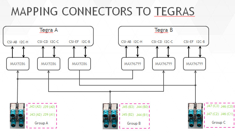
Mapping Connectors to Tegra Chips
Each GMSL camera group can be routed to one or both Tegra chips via a GMSL deserializer.
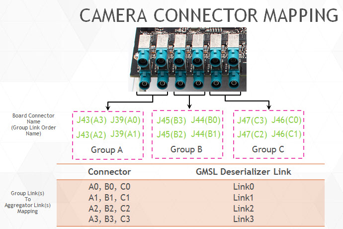
Connecting Cameras to DRIVE PX 2
When you connect cameras to a specific camera group, you must attach the cameras in sequential order. For example, within Group A:
• Attach the first camera to A0.
• If used, attach the second camera to A1.
• If used, attach the second camera to A2.
• If used, attach the second camera to A3.
If you fail to attach cameras in this order, NvMedia generates an error message.
Homogeneous Camera Types
With the DRIVE PX 2 platform, homogeneous camera types are required per camera group.
• All cameras within a particular camera group must be of the same type.
• Each group can have a different type of camera.
For example, the cameras attached to group A must all be OV10640 or OV10635; they cannot be mixed.
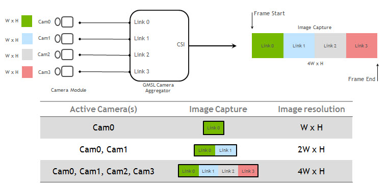
Default Aggregator Link Mapping
The following diagram shows how the digitized camera pictures are aggregated into a frame, where the image from the first camera appears first in the frame and the image from the last camera appears last in the frame. The frame size changes depending on how many cameras are connected.
All the sample applications that process images provide a ‑‑aggregate <n> option to specify the number of aggregated images in the frame. In this option, <n> maps as follows:
• n=1 maps to link0
• n=2 maps to link0 and link1 etc.
• n=4 maps to all links
The number of cameras connected must match the number specified in the
--aggregate option.
For guidance on extracting camera images from frames, see the
NvMedia Image Processing Sample Application.
MAXIM GMSL (Optional)
MAXIM Gigabit Multimedia Serial Link (GMSL) provides a compression-free alternative to Ethernet that is faster and more reliable than Ethernet. With this option you use MAX9271 (on the camera) and MAX9286/96799 (on DRIVE PX 2). It provides these features:
• Can drive a cable length of ~15 m
• Provides Forward channel (video data) and Back channel (control data)
• Synchronizes multiple cameras
• Delivers Power over Coax (PoC)
• Provides diagnostics for failure
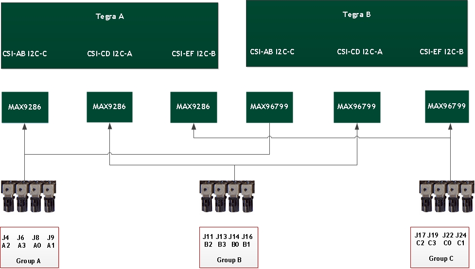
Mapping Connectors to Tegra Chips
Each GMSL camera group can be routed to one or both Tegra chips via a GMSL Deserializer.
Camera Power Control and Simultaneous Camera Capture
The NvMedia camera applications can use an Ethernet-based Control Communication protocol to request camera power on/off at the AURIX processors. It is not necessary to manually turn the camera power on/off through the AURIX shell interface. It is also possible to capture cameras on DRIVE PX 2 at both Tegra A and Tegra B simultaneously.
Note: | Both Tegra chips must be flashed and booted for these configurations to work properly. For more information, see Flashing DRIVE PX 2. |
To enable camera applications to use Ethernet-based control communication
1. Start camera capture at either Tegra A, using commands as described in the appropriate sample application in the NvMedia Sample Applications.
For example, for Tegra A Continental OV10640 camera connected to A0 port, and an HDMI monitor connected to the Tegra A HDMI port.
2. From the Tegra A Ubuntu 16.04 desktop, launch a terminal window and navigate to the following directory.
cd /home/nvidia/drive-t186ref-linux/samples/nvmedia/ipp_raw
3. Enter the following command.
./x11/nvmipp_raw -cf drive-px2-a.conf -c dvp-svc210-raw12-1280x1080-ab -d 0 --nvplugin
Where:
• drive-px2-a.conf specifies the Tegra A configuration file that specifies all the parameters for your configuration.
• dvp-svc210-raw12-1280x1080-ab specifies the capture-name parameter as defined in the configuration file for the Conti OV10640 camera connected to connector A0.
• 0 specifies the display number.
4. To obtain the available display devices for Tegra, run the following command:
nvmipp_raw -h
The available display devices are identified.
5. Select the desired display ID. --nvplugin is the NVMedia IPP plugin for the control algorithm components.
6. To start capture at Tegra B with the same set up as in Step 2 above (i.e., after starting capture on Tegra A), append the --slave option to the above command.
For example, for Tegra B Conti OV10640 camera with an HDMI monitor connected to the Tegra B HDMI port.
7. From the Tegra B Ubuntu 16.04 desktop, launch a terminal window and navigate to the following directory.
cd /home/nvidia/drive-t186ref-linux/samples/nvmedia/ipp_raw
8. Enter the following command.
./x11/nvmipp_raw -cf drive-px2-b.conf -c dvp-svc210-raw12-1280x1080-ab -d 0 --nvplugin --slave
Where:
• drive-px2-b.conf is the Tegra B configuration file that specifies all the parameters for your configuration.
• dvp-svc210-raw12-1280x1080-ab specifies the capture-name parameter as defined in the configuration file for the Conti OV10640 camera connected to connector A0.
• 0 specifies the HDMI display.
• --nvplugin specifies the NVMedia IPP plugin for the control algorithm components.
• --slave specifies that the application is being run on a slave Tegra, which is Tegra B in this case.
Simultaneous Capture with MAX96799 Aggregator
Due to the
mapping of the connectors on the Tegra chips (described earlier), when a MAX96799 aggregator is connected to Tegra B, it shares the same camera and serializer with a MAX9286 aggregator connected to Tegra A. Consequently, when MAX96799 is turned on, it automatically generates a FRSYNC and the reverse control channel is enabled by default.
However, for simultaneous capture, if the camera application is started in slave mode on Tegra B, after the camera application starts in master mode on the same camera group of Tegra A, FRSYNC generated by MAX9286 can interfere with the FRSYNC generated by MAX96799. The I2C transaction between Tegra A and the camera/serializer can interfere with the I2C transaction from Tegra B through the MAX96799.
This issue is resolved when using the new MAX96799 Revision 0x8. The aggregator in this revision does not power up the reverse channel transmitter by default. Therefore, it does not generate FRSYNC and does not enable the reverse control channel when powered up.
Using a MAX96799 Revision Older Than 0x8 for Simultaneous Capture
If your DRIVE PX 2 is using an older MAX96799 revision for simultaneous capture, a warning message appears after the camera application starts on Tegra B in slave mode. This warning message displays error messages similar to the following:
/**************** Warning message ****************/
Warning: Due to a hardware limitation with MAXIM 96799 chip on the DRIVE PX 2 platform,
intermittent errors messages, similar to the following, are displayed during simultaneous capture
with infrequent functional quality impact
Intermittent ERROR messages :
FlushCacheRegister - Error -7
ISCThreadFunc: NvMediaISCSetWBGain failed
captureGetErrorStatus: CsimuxFrameError
tegra-vi4 15700000.vi: error notifier set to 1
For further details, consult the Implementation Notes section of the Release Notes
and the NvMedia Sample Applications in the PDK.
/***********************************************/
Functional Quality
The above messages do not impact camera functionality. However, sometimes the following issues may be observed:
• The color of the image on the display is corrupted
• The display is stuck, and the camera application stops
Running Camera Applications Only on Tegra B
Note: | Before running camera applications only on Tegra B, you must disable FRSYNC and the forward/reverse control channel of Tegra A aggregator. |
The DRIVE PX 2 MAX9286 aggregator from Tegra A has a termination resistor for GMSL link communication. MAX96799 aggregator from Tegra B does not have a termination resistor and depends on the termination resistor on MAX9286.
To capture an image on Tegra B once after boot
1. Turn MAX9286 aggregator on
2. Disable FRSYNC and the forward/reverse control channel on MAX9286 aggregator to avoid any interference with MAX96799
After the kernel boots on Tegra A, the following occurs in the board initialization scripts:
• MAX9286 is powered up by default
• FRSYNC and the forward/reverse control channel are disabled
Now the camera applications can run on Tegra B once after boot.
Running camera applications on Tegra A re-enables the forward/reverse control channel and FRSYNC from MAX9286.
To run the camera applications on Tegra B only for second and subsequent trials
• Run the following commands on Tegra A to, power up MAX9286, disable FRSYNC, and disable the forward/reverse control channel:
For Camera Group A execute:
echo 1 > /sys/kernel/debug/isc-mgr.7.a/pwr-on
sleep 0.5
echo 1 > /sys/kernel/debug/isc-mgr.7.a/isc-dev.7.48/offset
echo 0xe2 > /sys/kernel/debug/isc-mgr.7.a/isc-dev.7.48/val
echo 0xa > /sys/kernel/debug/isc-mgr.7.a/isc-dev.7.48/offset
echo 0x00 > /sys/kernel/debug/isc-mgr.7.a/isc-dev.7.48/val
For Camera Group B execute:
echo 1 > /sys/kernel/debug/isc-mgr.2.c/pwr-on
sleep 0.5
echo 1 > /sys/kernel/debug/isc-mgr.2.c/isc-dev.2.48/offset
echo 0xe2 > /sys/kernel/debug/isc-mgr.2.c/isc-dev.2.48/val
echo 0xa > /sys/kernel/debug/isc-mgr.2.c/isc-dev.2.48/offset
echo 0x00 > /sys/kernel/debug/isc-mgr.2.c/isc-dev.2.48/val
For Camera Group C execute:
echo 1 > /sys/kernel/debug/isc-mgr.1.e/pwr-on
sleep 0.5
echo 1 > /sys/kernel/debug/isc-mgr.1.e/isc-dev.1.48/offset
echo 0xe2 > /sys/kernel/debug/isc-mgr.1.e/isc-dev.1.48/val
echo 0xa > /sys/kernel/debug/isc-mgr.1.e/isc-dev.1.48/offset
echo 0x00 > /sys/kernel/debug/isc-mgr.1.e/isc-dev.1.48/val