Flashing the Board
Note: | For convenience during flashing, the information in this chapter has been duplicated from the OS-agnostic chapter in Foundation 5.0 SDK Development Guide. |
This topic contains instructions for using the Bootburn utility to flash NVIDIA® Tegra® boards with the boot loader, kernel, and file system.
Bootburn
Bootburn is a shell script that:
• Boots the device in the recovery-mode with RAMDisk.
• Signs or generates the images on the host.
• Transfers the images to
target using ADB.
• Flashes the boards.
Bootburn automatically resizes the rootfs image on the target to optimize the available storage on the partition dedicated to it, either on eMMC or NOR.
Bootburn supports a host NFS share as the mount point for the target rootfs. This feature provides a convenient way for developers to copy files between the target and host for rapid development. In this case, the uncompressed target rootfs directory on the host is leveraged directly by the target.
Bootburn relies on the Foundation SDK 5.0 Foundation layer to provide the flashing and boot loader functionality. You configure it with the CFG file rather than with Bootburn command-line parameters; Bootburn supports limited command line options.
For more information:
Bootburn Command Usage
Run the bootburn.sh script from a shell on your host Linux system:
./bootburn.sh <options>
Bootburn Options
The following table describes the supported options.
Options | Description |
-a | Flashes Android images. |
-b <p3407-t186|p2379c01-t186a|p2379c01-t186b> | Provides the board name and revision. Flashes QNX IFS. See Section 1.0 of the Release Notes for your release to confirm your board and revision information. |
-d <partition_name> <dtb_file> | Specifies the DTB file to flash and the target partition. The default file is defined in BoardSetFilePathsAndDefaultValues. bpmp-fw-dtb and kernel-dtb may be specified simultaneously. Note: This option is not intended to specify kernel-dtb in Hypervisor. |
-e <emulation_target> | Specifies the target board for emulation. Valid emulation targets are: reilly, ohara-gfx, ohara-compute, drew-gfx, and drew-compute. |
-h | Provides guidance on the actions and options of bootburn. |
-l | Flashes Linux images. |
-o | Skips flashing of recovery partitions. |
-p <key_file_path> (lower-case p) | Signs the boot loader, secure OS (TOS), kernel and BCT binary, then flashes the device. <key_file_path> must be the full pathname of the key_file. |
-q | Flashes QNX images. |
-s (lower-case s) | Skips flashing the file system. Use the -s flag only when the target file system is already flashed. |
-t <output_directory> | Specifies the output directory where images to be flashed onto the target are to be stored. The default directory is named _temp_dump, and is present in the flashing directory. |
-u <partition_name1> <partition_name2> … (lower-case u) | Updates the partition name(s) and does not write anything else. Partitions bct, mb1-bootloader (-r), and pt cannot be updated using this option. A guest partition’s partition name includes a prefix that indicates the guest ID, e.g. the kernel DTB partition of guest 1 is 1_kernel-dtb. To update a rebuilt kernel, use this option instead of the default bootburn command, which updates all the partitions of the boot medium (NOR): 1. Back up the original kernel binaries’ Image and zImage files. 2. Copy the updated Image and zImage files to the directory: <top>/drive-t186ref-linux/kernel-rt_patches 3. Enter this command to update the partition: ./bootburn.sh -b <p3407-t186|p2379c01-t186a|p2379c01-t186b> -u kernel 4. To identify the partition name, consult the configuration file used for flashing. |
-x <aurix_port> | Specify the AURIX port for putting the Tegra devices in recovery and booting them after successfully flashing them. Valid only for NVIDIA DRIVE PX 2 systems. For example: -x /dev/ttyUSB1 |
-z <board_info>- | Provides the board information options, which include: • --skunum: Specifies the board SKU_Info, such as: 699-62382-0010-100. The label on your board provides the value to use. SKU_Info is mandatory for the -z option. • --setskuversion: Specifies AB. The label on your board provides the value to use. AB is mandatory for the -z option. • --setprodinfo: For example, 600-62379-0100-100 AB. This option is equivalent to --skunum and --setskuversion. • --setboardserial: Specifies the five-digit serial number. • --setmacid mac0 <0xaabbccddeeff>: Specifies a 6‑byte hexadecimal serial number. Make sure when using the --setmacid option to give every device a unique MAC ID. The -z sub-options are enclosed in quotes, and must include --skunum and --setskuversion. The other sub-options are optional. If they are provided, they are are stored on the target. For example: -z "--skunum 699-62382-0010-100 --setskuversion AB --setprodinfo 699-62382-0010-100 AB --setboardserial 00250 --setmacid mac0 0x00504b94df" |
-B <boot_device> | Specifies the boot device, which must be either qspi (the default) or emmc. |
-C (upper-case C) | Specifies use of debug binaries for the boot loader. |
-D | Directs bootburn debug output to stdout along with the tool’s regular output. If -D is not specified, debug output goes to a temporary file. |
-E | Enables DRAM ECC. |
-G | Flashes Integrity images. |
-H | Flashes the Hypervisor image (the default). |
-I <bus_id> <device_id> | Flashes a specific Tegra device when multiple devices are in recovery. To get the bus and device ID of each Tegra device in recovery, enter the lsusb command on the host. For example, if lsusb gives the following output: Bus 003 Device 105: ID 0955:7018 NVidia Corp. Bus 003 Device 104: ID 0955:7018 NVidia Corp. Then flash the second Tegra device with the -I option as in this example: -I 003 104 |
-L | Enables low power modes. This option requires that the spe-fw and WB0 firmware packages be included in the bootburn configuration because low-power modes require them. |
-M | Specifies development version firmware. |
-R | Specifies RCM boot support, where the device boots without being flashed. When the target is in recovery mode, this option causes the flashing script to download all binaries, other than BCT, from the host. The target then reads the BCT from storage and other binaries from RAM. It boots the kernel directly on RAM. This option is much faster than when flashing also occurs. It is especially useful during debugging. Use the -R flag to initiate RCMBOOT with any of the commands mentioned in this table. |
-S (upper case S) | Skips confirmation prompts from bootburn, as if “y” is selected for each prompt. |
-T | Enables tracing. Tracing logs are stored under the bootburn directory as log_trace*.txt. |
-V (upper case V) | Specifies read-back verification, where the binary images are read back (after writing) from the target’s storage and compared with the original binary images. The two sets of images are compared to detect discrepancies. |
Kernel Parameter Combinations
The following table shows the possible combinations of kernel parameters nfsdev, ip, and nfsroot. Error indicates that the initramfs shell is started.
nfsdev | ip | nfsroot | Result |
(not set) | (not set) | (not set) | no network; root must be set in some other way |
(not set) | (not set) | set | error; needs IP configuration |
(not set) | set | (not set) | error; no root path to mount |
(not set) | set | set | valid combination |
set | (not set) | (not set) | valid combination; DHCP request is sent |
set | (not set) | set | error; needs IP configuration |
set | set | (not set) | error; no root path to mount |
set | set | set | valid combination; no DHCP requests |
More Information
Note: | Prior to executing bootburn.sh first move to its location with the following command: cd drive-t186ref-foundation/tools/host/flashtools/bootburn |
The following list provides additional information on using bootburn options.
Getting Help
• For help on the Bootburn CFG file syntax, execute:
./bootburn.sh -h
Passing Additional Kernel Parameters
To pass additional kernel parameters, modify the os_args parameter of the kernel-dtb and kernel-dtb-r partitions in this file.
• For Linux:
drive-t186ref-foundation/virtualization/pct/<platform>/linux/linux_storage.cfg
• For QNX:
drive-t186ref-foundation/virtualization/pct/<platform>/qnx/qnx_storage.cfg
Where <platform> is:
• For DRIVE™ PX 2 ACr (P3407): p3407-t186
• For DRIVE PX 2 ACh (P2379) Tegra A: p2379c01-t186a
• For DRIVE PX 2 ACh (P2379) Tegra B: p2379c01-t186b
To bind:
• For Linux:
cd <
top>/drive-t186ref-foundation
make -f Makefile.bind PCT=linux BOARD=<platform>
• For QNX:
cd <
top>/drive-t186ref-foundation
make -f Makefile.bind PCT=qnx BOARD=<platform>
To flash all images for either Linux or QNX:
cd <
top>/drive-t186ref-foundation/tools/host/flashtools/bootburn
./bootburn.sh -b <platform>
To flash kernel-dtb only:
cd <
top>/drive-t186ref-foundation/tools/host/flashtools/bootburn
./bootburn.sh -b <platform> -u 1_kernel-dtb
Updating the Path for the targetfs
To update the path for the targetfs, modify the dirname parameter of the FS partition in:
drive-t186ref-foundation/tools/host/flashtools/bootburn/quickboot_qspi_linux[_initramfs].cfg
Applies to: This step applies to the CFG file used for eMMC boot, i.e., modify dirname in the file that does not have _initramfs in its filename.
Configuring Hypervisor-Linux to Boot Using rootfs Over NFS
For guidance on configuring Hypervisor-Linux to boot using rootfs over NFS, refer to the _initramfs version of:
drive-t186ref-foundation/tools/host/flashtools/bootburn/quickboot_qspi_linux[_initramfs].cfg
Make similar changes in the storage CFG at:
drive-t186ref-foundation/virtualization/pct/<platform>/linux/linux_storage.cfg
Where <platform> is:
• For DRIVE™ PX 2 ACr (P3407): p3407-t186
• For DRIVE™ PX 2 ACh (P2379) Tegra A: p2379c01-t186a
Note: | When Ubuntu 14.04 or 16.04 LTS is used for the host PC for flashing, when DRIVE PX 2 is placed in recovery mode and flashed messages similar to the following appear: Unable to mount FunctionFS gadget (adb)
Unable to open MTP device '[usb:001,050]' This is due to gvfs-mtp-volume-monitor server trying to mount the ADB device using the MTP protocol. Since MTP is not used for flashing, this message can be ignored. Issue the following command to kill the server to prevent the popup from occuring again: sudo killall gvfs-mtp-volume-monitor |
Using Hypervisor
For SDK releases that do not support dual MMC controllers, it is not possible to use a rootfs on a second MMC instance for the second guest operating system.
To use Hypervisor
1. Install Foundation SDK, ensuring that the GNU Toolchain is installed. The toolchain is installed in:
2. Ensure DHCP/NFS is set up according to your Linux, QNX, or Android Development Guide.
3. Install Foundation SDK packages for the operating systems, and in the SDK installation folder, run the following command:
export PDK_TOP=${PWD}
4. Define the CROSS_COMPILE variable to hold the path of the 4.9 toolchain with the following commands:
export CROSS_COMPILE=$PDK_TOP/toolchains/tegra-4.9-nv/usr/bin/aarch64-gnu-linux/aarch64-gnu-linux-
The CROSS_COMPILE variable is a prefix for the path to the correct cross-compiler toolchain binary, completed in Makefile.bind.
5. Set up UART and terminal utility:
cd <top>/drive-t186ref-foundation/tools/host/uart_muxer
make
6. Create nodes by running the following command:
<
top>/drive-t186ref‑foundation/tools/host/uart_muxer/uart_muxer -g <N> -b <M> -d <console>
Where:
• <N> defines the number of individual terminals to be created. This should be equal to (PLAT_NUM_GUESTS + 1) specified in platform_config.h for the PCT configuration in use. See the following file:
<top>/drive-t186ref-foundation/virtualization/pct/<p3407-t186|p2379c01-t186a|p2379c01-t186b>/single_vm/platform_config.h
• <M> defines the terminal to where Hypervisor messages will be forwarded. This terminal is also used to interact with Hypervisor debug console. The value of <M> is equal to PLAT_NUM_GUESTS.
• <console> is:
• For DRIVE™ PX 2 ACr (P3407): /dev/ttyUSB2
• For DRIVE™ PX 2 ACh (P2379) Tegra A: /dev/ttyUSB2
• For DRIVE PX 2 ACh (P2379) Tegra B: /dev/ttyUSB6
7. Run a terminal utility on each of the created /dev/pts/X nodes.
8. Alternatively, use the uart_muxer.sh wrapper script to automatically start terminals on each of the nodes with the command described in step 5 above.
To flash Hypervisor with a single OS configuration
1. Prepare a Foundation boot image by executing these commands:
<
top>/drive-t186ref‑foundation
make -f Makefile.bind BOARD=<p3407-t186|p2379c01-t186a|p2379c01-t186b>
Flashing DRIVE PX 2
This topic explains how to flash DRIVE PX 2. The procedures in this topic use the AURIX serial console to interface with the Infineon AURIX 32-bit TriCore microcontroller.
This SDK includes Elektrobit tresos, which in turn includes the Infineon AURIX 32-bit TriCore microcontroller. For more information about the tresos software suite, see:
Note: | Prior ADB configurations (e.g., ADB server running, ADB aliases with paths) may interfere with the Bootburn shell and cause it to fail with USB errors. Running bootburn.sh with bash -x reveals these issues. |
Prerequisites
• You have successfully done one of the following:
• Used SDK Manager to install the software for your platform.
• Manually installed Foundation and Linux releases.
For more information, see “Installing Foundation” and the installation procedures in the Foundation Development Guide.
After you have successfully installed the software, the following directories are created:
<top>/drive-t186ref-foundation
<top>/drive-t186ref-linux
• You have configured the port and baudrate of a serial controller, such as Minicom.
To flash Hypervisor with a single OS configuration with a new image
1. Prepare a foundation boot image by executing the following commands:
cd <
top>/drive-t186ref-foundation
make -f Makefile.bind BOARD=<platform> PCT=linux
Where <platform> is:
• For DRIVE™ PX 2 ACr (P3407): p3407-t186
• For DRIVE™ PX 2 ACh (P2379) Tegra A: p2379c01-t186a
• For DRIVE PX 2 ACh (P2379) Tegra B: p2379c01-t186b
2. Connect the USB A cable to DRIVE PX 2.
If no other USB/Serial adapters are connected to the host, the ttyUSB port is as follows:
• AURIX UART: /dev/ttyUSB1
• Tegra A (or P3407 Tegra) UART: /dev/ttyUSB2
• Tegra B UART: /dev/ttyUSB6
• Tegra A (or P3407 Tegra) USB for flash
• Tegra B USB for flash
If other USB serial adapters are already in use, the host takes relative numbering.
3. Use the AURIX serial console to put the Tegra devices into Recovery mode for flashing.
4. On the host system, verify that Tegra is in recovery mode using the following lsusb command to display the NVIDIA device.
lsusb | grep -i nvidia
Bus 001 Device 006: ID 0955:7721 Nvidia Corp
5. Program the boot image and partition by running:
cd <top>/drive-t186ref-foundation/tools/host/flashtools/bootburn
./bootburn.sh -b <platform>
Where t186ref is:
• For DRIVE™ PX 2 ACr (P3407): p3407-t186
• For DRIVE™ PX 2 ACh (P2379) Tegra A: p2379c01-t186a
• For DRIVE PX 2 ACh (P2379) Tegra B: p2379c01-t186b
6. Once flashing is complete, exit recovery mode and reboot DRIVE PX 2 from the Aurix console as follows.
tegrarecovery <device> off
tegrareset <device>
Where <device> is:
• For DRIVE PX 2 ACr (P3407): not needed
• For DRIVE PX 2 ACh (P2379) Tegra A: a
• For DRIVE PX 2 ACh (P2379) Tegra B: b
Flash both DRIVE PX 2 ACh Tegra devices in parallel
For DRIVE™ PX 2 ACh (P2379), both Tegra devices can be flashed in parallel, using this procedure. The procedure also eliminates the need to put the Tegra processor(s) in recovery.
1. Determine the serial port of the AURIX port on your host.
2. Close the AURIX console and make sure no other process is accessing it.
3. Flash both DRIVE PX 2 Tegra devices in parallel with the following command (where AURIX enumerates at /dev/ttyUSB1):
./bootburn.sh -b <platform> -x /dev/ttyUSB1 <other_options_and_parameters>
Where <platform> is:
• p2379c01-t186 to flash Tegra A and B simultaneously
• p2379c01-t186a to flash Tegra A only
• p2379c01-t186b to flash Tegra B only
The Encrypted User Data Partition
The encrypted user data partition is disabled by default. The following instructions describe how to enable the encrypted file system.
Enabling the Encrypted Partition on Ubuntu
By default, the encrypted user data partition is disabled. This topic explains how to enable it on Ubuntu root file systems. For information on establishing a key for encrypting the partition, see
Key for Encrypting User Data Partition in this topic.
To enable the encrypted user data partition on an Ubuntu root file system
1. Enter the following commands:
cd <
top>/drive-t186ref-foundation/virtualization/pct/<p3407-t186|p2379c01-t186a|p2379c01-t186b>/linux
cp global_efs_storage.cfg global_storage.cfg
2. Perform the appropriate procedure described in the section
Flashing DRIVE PX 2, earlier in this chapter.
Getting Keys for Encrypting User Data Partitions
The following types of keys are used for encrypted file systems:
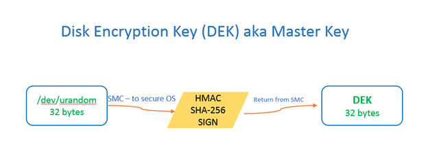
• Disk Encryption Key (DEK), which is also known as the master key. DEK is the key with which the data flowing between the file system and the disk is encrypted (and decrypted).
• Passphrase/Password is the string/pattern input by the user to setup disk encryption. The same input is later used to enter/unlock/decrypt the user data. In automotive use case, it is assumed that there is no user interaction to setup/enter a passphrase each time. So the system sets and stores a passphrase which it uses on every boot.
HW Backed DEK
The DEK is derived from a /dev/urandom buffer with 32-bytes of random data. To enhance security and add randomness, the random buffer is then HMAC-SHA-256 signed in the secure world and returned to cryptsetup. The secret key portion for HMAC signature is derived from the EKS blob provisioned into the device.
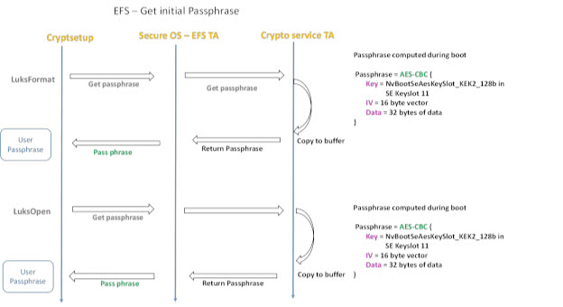
Passphrase/Password
For the passphrase, we call into secure world to get the user passphrase. The flow chart/block diagram of how it is derived is given below.
The steps for deriving a HW-backed passphrase are:
1. Getting an initial passphrase.
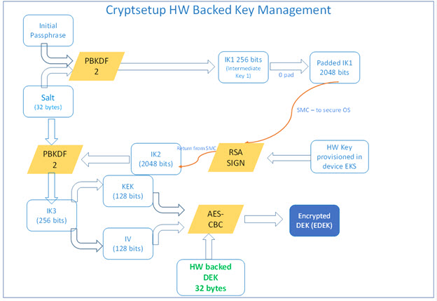
2. Using the initial passphrase to derive the HW-backed passphrase.
Getting an Initial Passphrase
The initial passphrase is derived by doing a AES-CBC-128 encryption of a fixed buffer, an IV and a key stored in the KEK2 provisioned by the OEM.
It is assumed here that the OEM has some MAC layer such as SE Linux to make sure the clients calling into secure OS are validated/access controlled to ensure passphrase is not given out to unknown clients.
Note: | A keyfile is also created during the first boot with 32-byte random vector from /dev/urandom, accessible only by kernel. Suppose the TZ call to get passphrase is not supported on some platform, it uses the passphrase in the keyfile as a secondary/backup option for the initial passphrase. The keyfile is stored in the usr partition of the root-file system. |
Deriving a HW-Backed Passphrase
The following illustration shows the logic applied to the initial passphrase to derive the HW-backed passphrase.