Setting Up DRIVE PX 2 AutoChauffeur (P2379)
This topic provides information for setting up the NVIDIA® DRIVE™ PX 2 platform.
Note: | Before flashing Tegra A or B, the AURIX switch must be toggled to RUN mode. |
Hardware Connectors
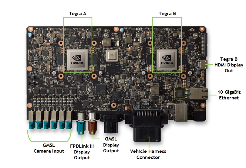
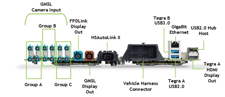
Consult the following images to identify the DRIVE PX 2 connectors.
Top View
Front View
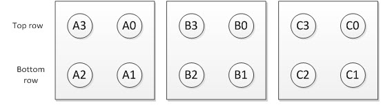
The following table identifies the group links to aggregator links mapping for each of the camera GSML groups.
Connector | GMSL Deserializer Link |
A0, B0, C0 | Link 0 |
A1, B1, C1 | Link 1 |
A2, B2, C2 | Link 2 |
A3, B3, C3 | Link 3 |
Vehicle Harness
The C0x vehicle harness provides the following connections:
Warning: | • Before connecting the system, ensure that the DRIVE PX 2 is not conntected to the AC power supply. Failure to do so may result in damage to the DRIVE PX 2. |
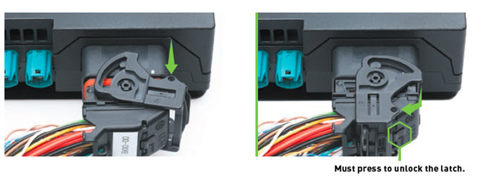
Connecting the Vehicle Harness
The following steps describe how to connect the vehicle harness to the Drive PX 2 connector.
To connect the DRIVE PX 2 to the harness
1. Connect the vehicle harness cable to the harness connector.
2. Lock the harness by placing the switch into the lock position with the latch (as shown in the above image).
3. Ensure the switch on the harness cable is in Normal Operation Mode.
4. Connect the DC Jack on the harness cable.
Follow the instructions in
Powering on the Device topic.
Connecting the Camera
The following steps describe how to connect a GMSL camera, for example OV10640, to DRIVE PX 2 at Port A0.
To connect the DRIVE PX2 to a camera
The mapping of the camera input connectors is as follows:
The physical connections can be remapped by the software. For details on the mapping, see
DRIVE PX 2 Platform Camera Setup.
1. Connect the GMSL camera using the Fakra Coax cable, for example OV10640, to the DRIVE PX 2 at PortA0.
Warning: | • The GMSL camera must be 8V tolerant. Refer to the NVIDIA DRIVE PX 2 Datasheet for details on the electrical requirements for the GMSL camera. • Always turn off main power before connecting or disconnecting cameras from NVIDIA DRIVE PX 2. • If the number of cameras is less than 4 and one fills any of the camera groups (A or B or C; they are all independent of each other) not in the order of lower indices, then you must remap and enable cameras with the NvMedia --csi-outmap and --cam_enable options. |
Connecting the FPDLink III Display
Connect a FPDLink III display adapter as follows:
1. Connect the blue connector on the FPDLink III adapter to the DRIVE PX 2 High Speed Display (HSD) connector using the HSD cable.
2. Connect the DVI cable to the FPDLink III adapter.
3. Connect the other end of the DVI cable to the display monitor.
4. Connect the power supply into the FPD-to-DVI adapter.
5. Connect the power supply to the wall socket.
Connecting the GMSL Adapter for High Speed Display
Connect the GMSL adapter as follows:
1. Connect the brown GMSL HDMI adapter to Drive PX 2 High Speed Display (HSD) connector using the HSD cable.
2. Connect the HDMI cable to the GMSL adapter.
3. Connect the other end of the HDMI cable to the display monitor.
4. Plug the micro-USB power supply into the GSML adapter.
5. Connect the power supply to the wall socket.
Connecting the HDMI Display
Connect the HDMI display as follows:
1. Connect the HDMI cable to the Tegra A HDMI port.
2. Connect the HDMI cable to the Tegra B HDMI port.
Consult the DRIVE PX 2 platform
Top View and
Front View to locate the Tegra A and Tegra B HDMI ports.
3. Connect the other end of the HDMI cable to the display monitor.
Connecting to the Network
DRIVE PX 2 contains network interfaces to provide the network connection for each Tegra chip. Consult the DRIVE PX 2
Front View to locate the required connectors.
1. Connect the Ethernet cable at either Ethernet interface on DRIVE PX 2 to a wall socket or a router that has an internet connection.
2. Optionally, connect your external USB devices, for example USB to Ethernet device, to each Tegra device using the appropriate USB port.