Table of Contents
- Note
- SW Release Applicability: This tutorial is applicable to modules in both NVIDIA DriveWorks and NVIDIA DRIVE Software releases.
The NVIDIA® Static Camera Calibration tutorial describes how to perform intrinsic and extrinsic calibration for a vehicle's cameras using the DriveWorks Static Calibration Tools.
The step-by-step tutorial covers the following:
- 1.0 Prerequisites : The materials required to perform calibration.
- 2.0 Scene Setup : The proper camera and target placements.
- 3.0 Capturing Data : Capturing the intrinsic and extrinsic data required for the tools.
- 4.0 Using the Calibration Tools : Generating camera calibration output.
- 5.0 Additional Information : Additional Information including intrinsic-only calibration.
1.0 Prerequisites
The following cameras and targets are required before proceeding in this tutorial.
1.1 Cameras
The following cameras are required for calibration:
AV Cameras
- N number of fixed focal length cameras. In this tutorial, 12 AR0231 cameras are used as an example.
- Cameras are mounted on vehicle or otherwise not expected to be purposely moved after completion of this tutorial.
- Referred to as "camera" or "cameras" throughout the remainder of this tutorial.
One Camera to support AV camera calibration
- Fixed focal length of roughly 18mm-30mm.
- At least 12MP resolution.
- Sensor size to be roughly Canon's ASP-C or Nikon's DX size (roughly 23mmx15mm).
- Referred to as "external camera" throughout the remainder of this tutorial.
1.2 Targets
This tutorial requires the use of targets to calibrate the vehicle's cameras.
The targets used in this tutorial can be found in the following folder:
data/tools/calibration/aprilTargets
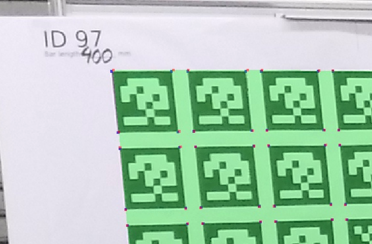
An example of the target used in this tutorial:
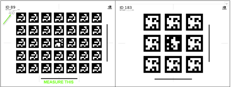
1.2.1 Target Prints
The targets must be printed as follows:
8 large targets (or more)
- Size 1m x 1m.
- Target IDs 89-101 in
data/tools/calibration/aprilTargets.
4 small targets
- A3 format.
- Target IDs 180-183 in
data/tools/calibration/aprilTargets.
- Note
- A target with the same ID cannot be reused multiple times.
- Although not recommended, it is possible to use targets other than the ones provided with the Static Calibration Tools.
1.2.2 Target Print Validation
For each target, measure the length of the horizontal bar in millimeters (mm) and note it in the corner, as demonstrated in the above image.
- Note
- Ensure the printouts have correct aspect ratios by comparing the length of the vertical and horizontal bars.
- If their lengths are not equal, the targets MUST be reprinted, as they do not have the correct aspect ratio.
- Additionally, ensure the targets are perfectly flat, rigid, and do not bend.
2.0 Scene Setup
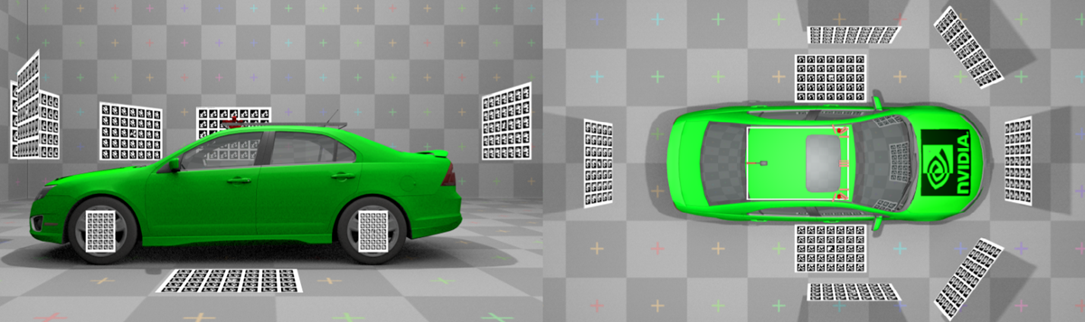
2.1 Camera Placement
Depending on the number and location of the cameras on the vehicle, different scene setups may be used.
In this tutorial, a setup with 12 cameras mounted on a car roof is used as an example.
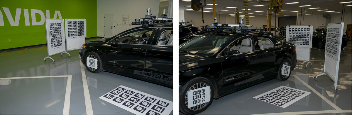
2.2 Target Placement
Ensure the following constraints when placing targets during scene setup:
- The 4 small targets are placed on the wheels, and that the target centers and wheel centers are aligned.
- Each camera requiring calibration must observe at least 1 large target.
- Each target covers the camera's field of view as much as possible.
- Each target is present only once in the scene.
In this tutorial, a set of 8 large and 4 small targets are used as an example.
3.0 Capturing Data
The following types of data must be captured for static camera calibration:
- Intrinsic Data: This only needs to be captured once if camera parameters i.e., lens, have not changed.
- Extrinsic Data: Includes images captured from the vehicle's cameras to be calibrated and images captured with the external camera.
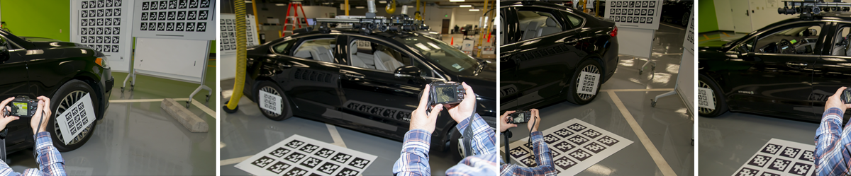
3.1 Capturing Data for Intrinsic Camera Calibration
To capture data for intrinsic camera calibration:
- Move a checkerboard pattern or AprilTag target in front of each camera requiring calibration.
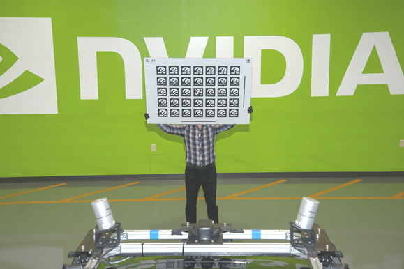 AprilTag in front of camera
- Setup and start the Recorder for all cameras requiring calibration. Refer to Basic Recording for more information how to setup recorder.
- Note
- To save disc space setup recorder to record h264/mp4 stream directly, e.g. by passing
format=h264,output-format=yuvas camera sensor properties.
- While the recorder is running, perform the following for each camera:
- Move the checkerboard pattern from left to right in front of the camera.
- While moving, rotate the pattern in all dimensions to calibrate pitch, roll, and yaw.
- While moving, get closer and further away from the camera to calibrate scale.
- Stop periodically while moving to allow motion-blur free constraint detection.
The calibration tool will automatically extract all valid frames from the recorded video.
Refer to 4.2 Intrinsic Camera Calibration.
3.2 Capturing Data for Extrinsic Camera Calibration
To capture data for extrinsic camera calibration, use one of the following methods to capture one image from each car camera:
3.2.1 Using the DriveWorks Recorder
Use the DriveWorks Recorder Tool to simultaneously record video from all cameras and ffmpeg to extract one frame from the video.
- Setup the Driveworks Recorder Tool as described in Basic Recording (use h264/mp4 recording)
- Extract individual frames with ffmpeg:
ffmpeg -i \<folder\>/camera_X.h264 -t 1 -f image2 camera_X.png
3.2.2 Using the DriveWorks Sample
Use the DriveWorks Sample sample_camera_multiple_gmsl to capture a frame.
- For 12 cameras of the same type execute:
./sample_camera_multiple_gmsl --selector-mask=111111111111
- Press F while the sample is running to capture a frame from each camera as a .png file.
Once you have followed one of the two methods described above, rename and copy the files to an appropriate location as indicated by the DriveWorks Calibration Tools.
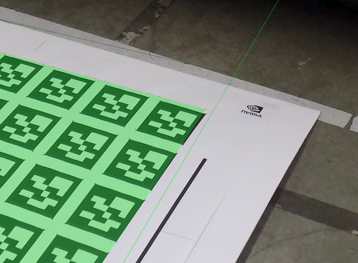
In addition to capturing frames from the vehicle's cameras, a set of images also needs to be captured with the external camera.
These images help construct a calibration graph as they introduce a link between targets not observable by the car cameras.
These targets can include ground targets, wheel targets, and between targets of individual cameras.
It is recommended you capture at least 20 images with the external camera, so that all possible target pairs are recorded.
Ensure these images simultaneously observe both the ground targets, and the wheel targets.
The following demonstrates the types of images to capture with the external camera:
- Note
- It is not required to perform intrinsic calibration for the external camera. Targets detected in the frame will be automatically used for intrinsic constraints.
- Therefore, it is important that there are at least 20 images provided for the external camera.
4.0 Using the Calibration Tools
The Static Calibration Tool suite consists of multiple command line tools. This tutorial covers the tools required for static calibration of the vehicle's cameras. There are additional calibration tools for auxiliary support and additional sensor. These are not covered in this tutorial. All tools used in this section are documented in Camera Calibration Tools.
- Note
- It is recommended to run the calibration tool suite on an x86 Host System due to the resource requirements of the internal optimization.
4.1 Directory Structure
The calibration tools expect a specific directory structure as well as a predefined collection of files:
4.1.1 targets.json
targets.json is a target database shipped with DriveWorks. It contains all the large targets that can be used in the scene.
Modify this file and change the barLength fields for all targets in the scene to the length (in meters) which you measured in 1.2.1 Target Prints.
4.1.2 special-targets.json
special-targets.json: The targets attached to the wheels and the targets that lie flat on the floor must also be declared in this file.
The structure of this file is as follows:
Ensure that the targets which are on the ground and which are attached to the wheels are correctly identified in this file.
4.2 Intrinsic Camera Calibration
This section requires the usage of the DriveWorks Intrinsics Constraints Tool, to extract intrinsics constraints used during calibration for each individual camera.
The input for this tool is the video recorded in 3.1 Capturing Data for Intrinsic Camera Calibration.
This tool will then export all required constraints and output them in a .json file to be placed in the /intrinsics/ subfolder in the directory structure.
4.2.1 For an 11x8 Checkerboard
Run the tool by executing:
./calibration-intrinsics-constraints
  --use-checkerboard=11x8
  --input-video=<video_path>/camera-0.h264
  --output=<calib_data_path>/intrinsics/camera-0.json
4.2.2 For an AprilTag Target Video
Run the tool by executing:
./calibration-intrinsics-constraints
  --targetDB=<calib_data_path>/targets.json
  --input-video=<video_path>/camera-0.h264
  --output=<calib_data_path>/intrinsics/camera-0.json
The tool will open a window playing back the input video and indicate with a red or green border if a new intrinsic constraint has been collected (i.e. target or checkerboard has been found).
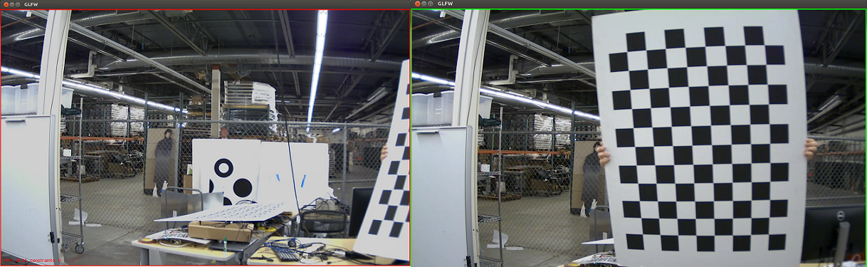
- Note
- It is important that the tool is able to find at least 30 constraints (checkerboards or AprilTags) per camera.
4.3 Extrinsic Calibration
This section requires the usage of the DriveWorks Graph Calibration Tool, to construct a graph-based representation of the data obtained, which is then further optimized.
Running this tool without parameters assumes you have the file structure specified in 4.1 Directory Structure.
The tool determines the names of the cameras from the extrinsics folder. It then searches the intrinsic folder for .json files corresponding with the intrinsics constraints.
The images captured with the external camera will also be used for intrinsic calibration for the external camera, and for extrinsics constraints.
The Calibration Tool will then use these images to construct a graph representation which is later optimized.
4.3.1 Extrinsic Calibration Setup
Ensure the following before proceeding:
- The images captured in 3.2 Capturing Data for Extrinsic Camera Calibration are placed in the
\<calib_data_path\>/extrinsicsfolder. The image file
names also match the intrinsics.jsonfile names generated in 4.2 Intrinsic Camera Calibration. - The images captured by the external camera are placed in the
\<calib_data_path\>/externalfolder.
4.3.2 Extrinsic Calibration Execution
Run the tool by executing the following:
./calibration-graph-cli --dir=<calib_data_path>
The tool outputs progress to the console. Take note of warnings in yellow and errors in red as they indicate possible problems with the calibration.
The following outputs are placed in the target folder:
calibrated-graph.jsonis the main output for this tool. This contains all constraints, the calibrated camera models, the camera poses, the target poses, etc.
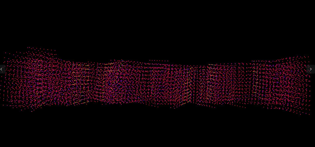
This is an intermediate format which is meant for machine consumption only.- Intrinsic validation images show the set of points used for intrinsic calibration:
- Blue dots = detected.
- Red dots = reprojected.
- Small yellow lines = line joining detection and re-projection.
- Large yellow lines = outliers.
The output is generated for all car cameras, (validation-intrinsics-<camera>.jpg) and the external cameras.
- Extrinsic validation images show the image used for extrinsic calibration with overlaid results, where:
- Detected targets have a green overlay.
- Detected tags have their corner detections with the same colors as their intrinsic re-projections.
- The ground plane is drawn as a series of green lines 1 meter apart. The lines at
x = 0andy = 0are orange.
The output is generated for all car cameras, and each external image (validation-<camera>.jpg).
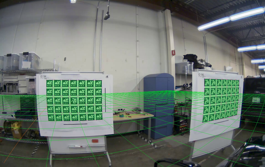
4.3.3 Extrinsic Calibration Validation
Validation images can be used to double check if the computed calibration is valid, i.e., if the green re-projections match the targets.
In the following image, a green mask clearly overlays the targets, and the corners are well aligned. This indicates a valid computed calibration.
In the following image, a green mask is misaligned with the target. This indicates the calibration results might not be correct, or that there is a problem with the calibration target.
- Note
- In most cases an invalid re-projection of the calibration mask occurs when:
- Intrinsic calibration is not well constrained. This occurs if the checkerboard or target was not adequately covering the camera field of view during intrinsic calibration. As an example, intrinsic validation images contain points that are well-detected and spread all over.
- Target corner detection failed or is not precise. This may occur if the image is blurry or low quality.
- Targets are not flat. This is the most likely reason for the misalignment. Ensure that all targets are flat, rigid, and do not bend, to prevent these issues.
4.4 Generating DriveWorks `rig.json` File
The Graph Calibration Tool also provides a calibrated-graph.json file as output. This file contains intermediate
calibration results which cannot yet be consumed by the NVIDIA® DriveWorks SDK. These results can be converted using the Calibrated Graph Tool into a valid DriveWorks SDK rig.json file representing the full calibrated camera rig configuration, and can be directly consumed by the DriveWorks modules, e.g., Rig Configuration.
To perform the conversion, run the tool by executing the following:
./calibration-graph-to-rig --graph=<calib_data_path>/calibrated-graph.json
The tool generates a rig.json file in the current folder. This file lists all cameras used during calibration with their final intrinsic and extrinsic calibration data.
If an existing rig.json is passed as input, all camera entries are modified with the new calibration results.
- Note
- The coordinate system conventions used by the calibration tools can be found in Coordinate Systems.
5.0 Additional Information
5.1 Intrinsic-only Calibration
The Static Calibration Tool suite supports calibration for intrinsic parameters only, if extrinsic calibration is not desired or required.
The procedure is similar to the full calibration workflow, with several modifications:
- Record videos with the checkerboard or AprilTag patterns described in 3.1 Capturing Data for Intrinsic Camera Calibration.
- Create the directory structure as described in 4.1 Directory Structure. Only include the
intrinsicsfolder andtargets.jsonfile. - For each camera, execute the intrinsic calibration application. This generates a set of
.jsonfiles for each camera. - Execute the Graph Calibration Tool as demonstrated in 4.3.2 Extrinsic Calibration Execution.
- This generates a
calibrated-graph.json filein the input directory, and intrinsic validation images as demonstrated in the section. Verify that these validation images meet the requirements described above.
- This generates a
- Execute the Calibrated Graph to Rig File Tool to populate a
rig.jsonfile with the result. Refer to 4.4 Generating DriveWorks `rig.json` File for more information.