
As HDR TVs and monitors are gaining popularity, there's an increased need for creating and presenting game content in HDR. This developer's guide aims at explaining HDR concepts and terminology, and also provides information on how to implement HDR into existing games and game engines.
HDR displays are capable of showing colors — typically a wider gamut than most standard displays — at higher luminance levels without washing them out. Furthermore, by storing color values with higher precision floating point buffers, a much higher dynamic range can be achieved with minimal error between shades of color and highlights and shadows can be preserved as well. The ColorWhitePaper document provided with this bundle covers some topics that are not covered in this guide. It is a recommended read for a more thorough understanding of Color and it would make some of the topics covered in this guide easier to follow.
This section of the guide goes through some common terms that are used in the HDR world. The sample app section will put all these terms to use and make things clearer.
A tone mapping operator has to meet several constraints.
We've found that the pipeline defined in ACES created by the Academy of Motion Pictures is a good fit. As a bonus, it is a standard that appears to have traction in a related industry. Tone mapping in ACES can (unsurprisingly) be described as filmic. This means that it applies a sigmoid-style curve in a logarithmic space to produce the tone mapping. Further, it performs the operations mostly independently on the color channels rather than operating strictly on luminance like many other operators. This characteristic makes the operator naturally desaturate when it reaches the limits of the present adaptation level. Highlights gently roll toward white, and shadows gently roll toward black.
Filmic operators have gotten a lot of traction with game developers over the past several years, because they offer a 'cinematic' look. Also, as they roughly model the behavior of film stock, they are taking over a century of refinement in how to capture and present an image that humans find pleasing or realistic. The full pipeline defined by ACES is more than what a game developer typically needs to concern themselves with, as it includes items related to cameras and archival storage. What we’re most interested in here is the imaging pipeline that specifies how to convert a scene-referred image for display across a variety of reference devices (from 48 nit projectors to 4000 nit HDR displays in the present reference implementation).
For us, ACES starts by taking a scene referred image and converting it into the wide-gamut working space used by ACES. At this point in the process, settings such as exposure are applied to get middle-gray to the expected 0.18 level (applying exposure doesn’t change an image from being scene referred, since exposure is just a linear scale). Prior to the tone mapping portion of the algorithm, ACES specifies that one or more Look Modification Transforms (LMT) may be applied to produce the intended look for the scene. Please refer to the next section on color grading for more.
Next, ACES applies what it refers to as the Reference Rendering Transform (RRT). The RRT contains a sigmoid-style curve in a very large range. It can be thought of as a base film operator that is independent of the intended display.
In the next step, ACES applies what is called an Output Device Transform (ODT). The ODT can be thought of as containing the output device specific portion of tone mapping. The ODT will contain a stronger sigmoid-style mapping to bring the data into the limited range of the intended output. It also handles conversion into the output color space, and any encoding necessary. The powerful concept here is the segmentation of operations, particularly device-independent versus device-dependent. The goal of the system is to enable adapting to many different display environments. The implementation section below has more information on how to incorporate the ACES tonemapper into your own game.
This section is out of place chronologically with the recommended pipeline, simply because our recommendation here is based heavily around the ACES workflow described in the last section. As we described, LMTs are the prescribed way to apply a specific look to a scene within the ACES pipeline. As opposed to the color grading game developers have frequently used in recent years, it is defined to happen against scene referred data, rather than against output referred data.
Today, many game developers use a very simple but powerful pipeline to handle color grading. They have a small (often 16^3) 3D LUT, which is indexed by the color after tone mapping. Artists are often given a default identity LUT overlaid on an image from the game, and then given free rein to modify it with global operations in an editor like Photoshop. After many layers of color balancing, curve modification, and hue shifting, the transformed LUT is extracted out of the image and used in game. In the worst case, all this is done without properly accounting for the non-linear encoding of sRGB.
While the process described above is extremely powerful for an artist, it poses some challenges with a flow that needs to contend with HDR. The primary issue is that the grading is all being done relative to output referred colors. This means that the grading doesn't map well to the larger range. Obviously, it is possible to just author another color grade for a different output space. However, now a developer needs to worry about keeping things in sync, and possibly worry about keeping multiple levels of grading (500 nits for OLED HDR, 1000 nits LCD HDR, 2000 nit HDR, etc.). Assuming that the tone map is invertible, it would be possible to map the changes back from the SDR space to the HDR space.
Unfortunately, tone mappers are never quite fully invertible once you get to the final image. (quantization and saturation, particularly in the highlight ranges). So mapping that operator backwards will lead to some degree of artifacts or limitations. Additionally, grading in the output reference space can result in the artist being driven to 'fix' tone mapper shortcomings. A common potential issue is with luminance only tone mappers. Because they are restricted to luminance only, they maintain saturation at all levels of luminance. This means that a heavily saturated highlight will actually appear dimmer, due to the natural restrictions of a display. However, an artist may now be tempted to throw some desaturation into those high ranges to make them look brighter. Now you’ve desaturated colors that you could represent well on an HDR display in an unnatural manner.
To solve these sorts of issues, ACES specifies using a Look Modification Transform for most of what we'd term color grading in games today. The LMT operates on the full range data. While it doesn’t have to be, an LMT will typically be a 3D LUT just like we’re used to. To compensate for the large range, the LUT needs a "shaper" function to more efficiently cover the space. Typically, a log function is a good enough solution for this. With log compression, a 32^3 LUT can cover a large range in the scene referred space with reasonably good precision.
For simplicity as you start out, a developer may wish to consider integrating a fairly restricted range of mathematical operators applied directly to the data. Gain, bias, contrast enhancement, and saturation may be enough for a lot of purposes. Further transforms, like processing in color opponent spaces like IPT may be useful to adjust balance between hues. Additionally, these operations can all ultimately be baked out into a simple LUT as described above for final deployment. Obviously, the solution proposed here cannot replicate everything that an artist might be doing today with the common color grading methods. Today, an artist can turn pure black to bright red if they really want to. In spite of this, we feel the path outlined is going to be a generally good one that will cover the needs and desires of most. It is something that seems to have some degree of support in the film industry, and we can do a lot worse than emulating a workflow that others with similar challenges utilize.
Color space sets up the output color space for the image. It is important to understand that the function of this control changes somewhat depending on the selected EOTF mode control described below. The output is in the color space selected. For example, changing from sRGB to BT. 2020 color space will show the image get substantially desaturated. This is because it is outputting color as if it is expecting the display to directly take BT 2020. Since the code is trying to output the same absolute color no matter which space you chose, choosing a wider color space means that the colors will appear more desaturated.
A color space generally consists of three things: a set of primaries, an encoding, and a white point. Color primaries for use in computer graphics are almost always red, green, and blue — each represented by a tuple (X,Y) of floating point numbers. However, there is still an important question of which shade of each. The encoding covers things like floating point versus normalized integer, but also items like non-linear transforms such as the sRGB function or similar gamma functions. Finally, a color space generally specifies an assumed white point. This allows the correction of the color balance under different viewing conditions (as you might do by changing the color temperature setting on your display).
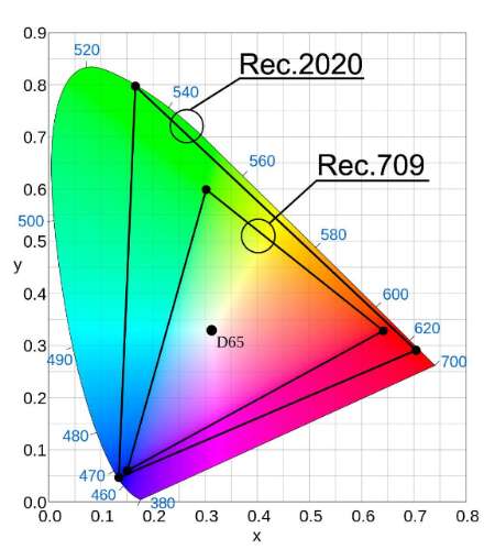
Rec.2020 vs Rec.709 (Courtesy avsforum.com)
The figure above shows the color gamut spectrum and the color gamut coverage for Rec.2020 (or BT.2020) and Rec.709 (sRGB) color spaces.
sRGB primaries are as follows:
EOTF stands for Electro-Optical Transfer Function. You should think of this as the modern gamma. This setting controls how the data is encoded before being passed to the display driver. In standard ACES, the EOTF is baked into each ODT (Output Device Transform). In our parameterized implementation, several EOTFs are selectable. The data flowing to the EOTF is in the intended output nit level. The selected EOTF remaps it to a mode that matches what the display or driver expects.
In sRGB mode, this means mapping the entire supported range to [0,1], then applying the sRGB transform. It is merely a representation that the OS or display driver converts to the proper EOTF for the display. When viewing scRGB content on a standard display, content appears much brighter, and the brightest parts of the image all appear clipped. This is because scRGB maps values brighter than standard sRGB white to values greater than 1.0. When displayed on an SDR monitor, all these values clip.
While the standard ACES implementation applies the curves independently to each of the red, green, and blue channels, some games have been designed against constant color tone mapping. This has been a common method in many tone mappers over the years. By applying the compression only to luminance, bright colors stay richly saturated at the cost of highlights clamping in an unnatural manner.
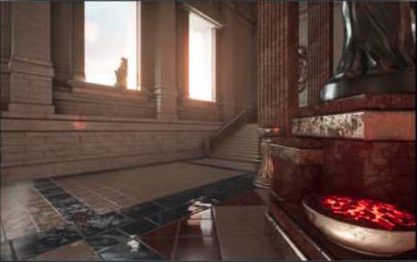
To aid for cases where the art is tuned toward this, we have added a control that can vary from 100% per-channel tone mapping to 100% luminance tone mapping. Enabling the luminance mode, and changing amount of luminance only weighting changes the results as depicted in the three figures below.
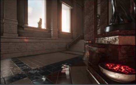
Default SDR tone mapper
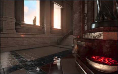
Fully saturated luminance only SDR tone map

50% luminance tone map
These are advanced controls that 99% of developers will want to ignore. The Color Appearance Transform (CAT) control is a transform shift between white points. Unless specifically working with content with a different white point specified, this should essentially always be on. The desaturation control handles a desaturation phase used in the SDR ACES implementation to compensate for the fact that the signal is generally fairly dim. The effect on the image is actually quite minor.
The reference ACES shaders have a simple method to adjust for the brightness of the surrounding environment. Since adapting to brighter environments changes the sensitivity of our eyes, they apply a power function to adjust from their reference dark environment to a dim environment. (This same adjustment also exists in related operations like color appearance models.)
In the two figures below, you can see the impact of applying an adjustment level beyond the standard level ACES prescribes for adjusting to dim. The 0.8 power function used here would be more appropriate for a pretty bright viewing environment. The lower the power used, the more you cram the colors toward the bright end of what the display can do. For instance a 0.8 will boost middle gray from 10 nits to 25 nits with the reference ACES 1000 nit ODT.

Adjusted for dark surround
Adjusted for bright surround
The curve settings all apply to the sigmoid-like curve applied during the ODT. These are the heart of the tone mapper, and the different ones provide the largest variance between target devices. We have a handful of settings that controls the curve.
The tone curve control selects the base curve. As mentioned above, we have implemented a solution where the reference curves can be reshaped to conform to somewhat different conditions than the reference. These tweaks are all included in the other curve settings. While it is hard to show the difference of HDR in an SDR document, the difference in the brighter regions of the figures above should be apparent. The higher input level supported by the 1000 nit curve allows detail to be preserved that otherwise would have just washed out.
It is important to note that the control contains both adjustable and reference versions of the curves. The reference versions all ignore the other curve settings, while the adjustable ones all take them into account.
The min and max stop parameters control the black and white saturation levels for the curve. A max stops value of 1 would mean that the curve reaches its peak output luminance with an input level of one stop above middle gray or 0.36. Similarly, a min stops value of -1 would mean that minimum output luminance (black) would occur with an input of 0.09. The list below shows the values from the ACES reference, as well as our sharpened 1000 nit curve.
Max CLL (Content Light Level) is the parameter that controls the maximum output luminance. -1 has the special value that it uses the curve's native value. It is probably fairly obvious that the native values for 1000 nit, 2000 nit, and 4000 nit are 1000, 2000, and 4000.
This parameter is a bit odd and unintuitive. It is a scale value on the output level for middle gray. For instance, if you like where the curve has highlights and blacks, but you think that the middle gray values are twice as bright as they should be, you could set this to 0.5. The output level of middle gray is essentially a relative value of the maximum luminance.
In the standard SDR curve, this level is 10%. If you are tone mapping to achieve better experiences on a really bright HDR display, you typically want to scale the middle gray back to where it normally would be in nits, and then use the rest of the range to cover the extended highlights. Since middle gray is normally 10% of max, and displays are often set around 100 nits of brightness, this means that the luminance of middle gray will be around 10 nits. When you turn up the display to 350 nits, you can either just make middle gray 35 nits (which may appear washed out unless you are in a bright room), or you can scale middle gray back down to around 10 nits and extend the range of the maximum stops to better represent brighter portions of the scene.
We store information about the display on which the authoring of the original content is done in the form of mastering display metadata. Depending on the technology used, this metadata can be used by the display to transform the data to a form that makes best use of the display's capabilities; or, if the display is not capable of doing this, the device capabilities are queried and data can be remastered on the source side.
Metadata information that is provided is limited to 16 bits for minimum and maximum luminance values. A minimum luminance value is typically a low value between 0.0 and 6.5535, inclusive and maximum luminance has an upper limit of 65535.0. The EGL spec for SMPTE_2086 will have more information about the exact values for different implementations. For the VisualizeHDR sample, sRGB primaries and white point are assumed with a maximum mastering display luminance of 1000 nits and minimum mastering display luminance of 0.
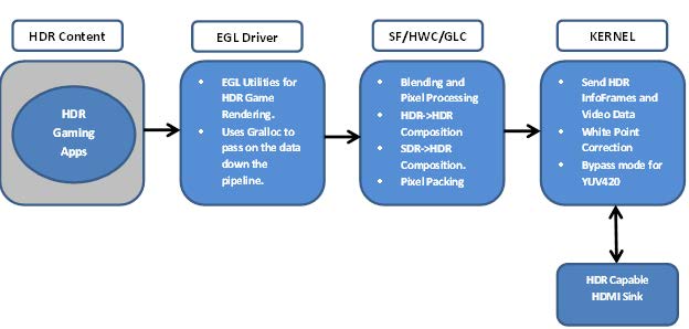
Android HDR Gaming Pipeline
The diagram above depicts HDR Gaming pipeline on Android and its end-to-end data flow. HDR gaming applications render content using EGL utilities on Android, which along with the metadata is passed onto hwcomposer using android gralloc module. Depending on the target capabilities, hwcomposer uses glcomposer to do the necessary composition and pixel packing (if required) and sends the data over to kernel. The kernel then forwards the data over to the target sink using the appropriate interface.

NVIDIA® GameWorks™ Documentation Rev. 1.0.220830 ©2014-2022. NVIDIA Corporation and affiliates. All Rights Reserved.