Hardware Layout#
Note
For the detailed specification of each connector, header and carrier board, please refer to the NVIDIA Jetson AGX Thor Developer Kit Carrier Board Specification.
IO Side Layout#


Mark. |
Name |
Note |
|
|---|---|---|---|
1 |
USB Type-A ports (2x) |
USB 3.2 Gen 2 (10Gbps) |
|
2 |
RJ45 Ethernet port |
5Gbps |
|
3 |
DisplayPort output |
||
4 |
HDMI output |
||
5a |
USB-C port with Force-Recovery Mode functionality |
|
|
5b |
USB-C port |
|
|
6 |
QSFP28 cage |
4x 25Gbps |
|
7 |
Micro-fit power input |
9-28V DC input (Up to 8A) |
|
8 |
Debug USB-C port |
(Behind the lid cover) |
Attention
If you are using an Ubuntu host PC to externally flash Jetson AGX Thor Developer Kit (using either the SDK Manager or the Linux_for_Tegra Flash Script), you need to connect a USB from your PC into USB-C port next to the HDMI connector (5a) and thus connect the USB-C power supply into the other USB-C port (5b).
If you don’t see APX device show up on lsusb commands ran on your PC even when you put the Jetson AGX Thor Developer Kit into the Force Recovery Mode (RCM), check whether the USB-C cable connection for flashing is going into the right USB-C port.
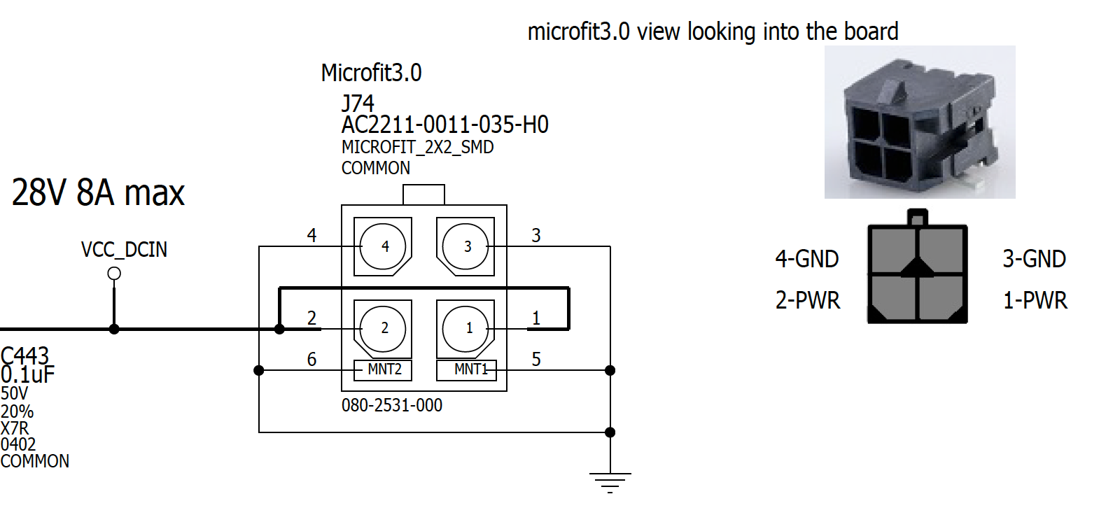
Micro-fit Power Connector Specification#
Pin Assignment#
Button Side Layout#


Mark. |
Name |
Note |
|
|---|---|---|---|
11 |
Power button |
||
12 |
Force Recovery button |
||
13 |
Reset button |
||
14 |
White LED |
How to enter Force Recovery Mode#
To enter Force Recovery Mode, follow the instructions below:
Press and hold the Force Recovery button (12 , the middle button)
While the Force Recovery button is pressed, briefly press the Reset button (13 , the right button)
Let go the Force Recovery button
The board will reboot into Force Recovery Mode.
Carrier Board Layout#
Note
The diagrams below are from NVIDIA Jetson AGX Thor Developer Kit Carrier Board Specification v1.0.
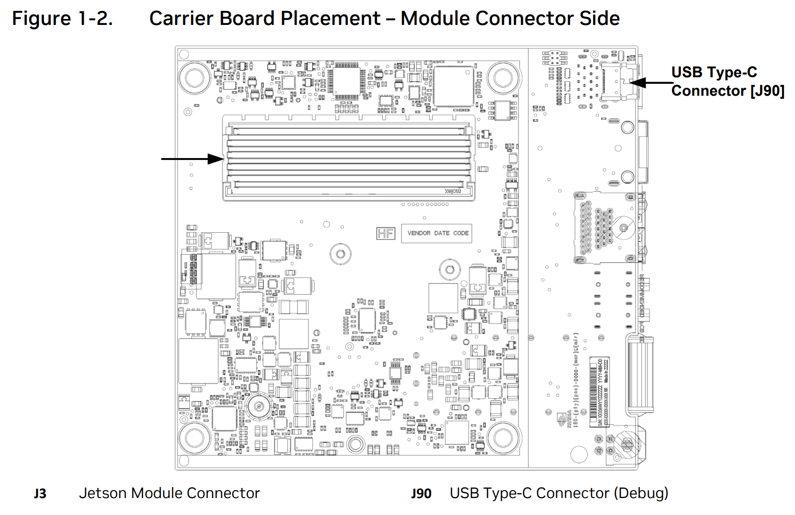
Module Connector Side Layout#
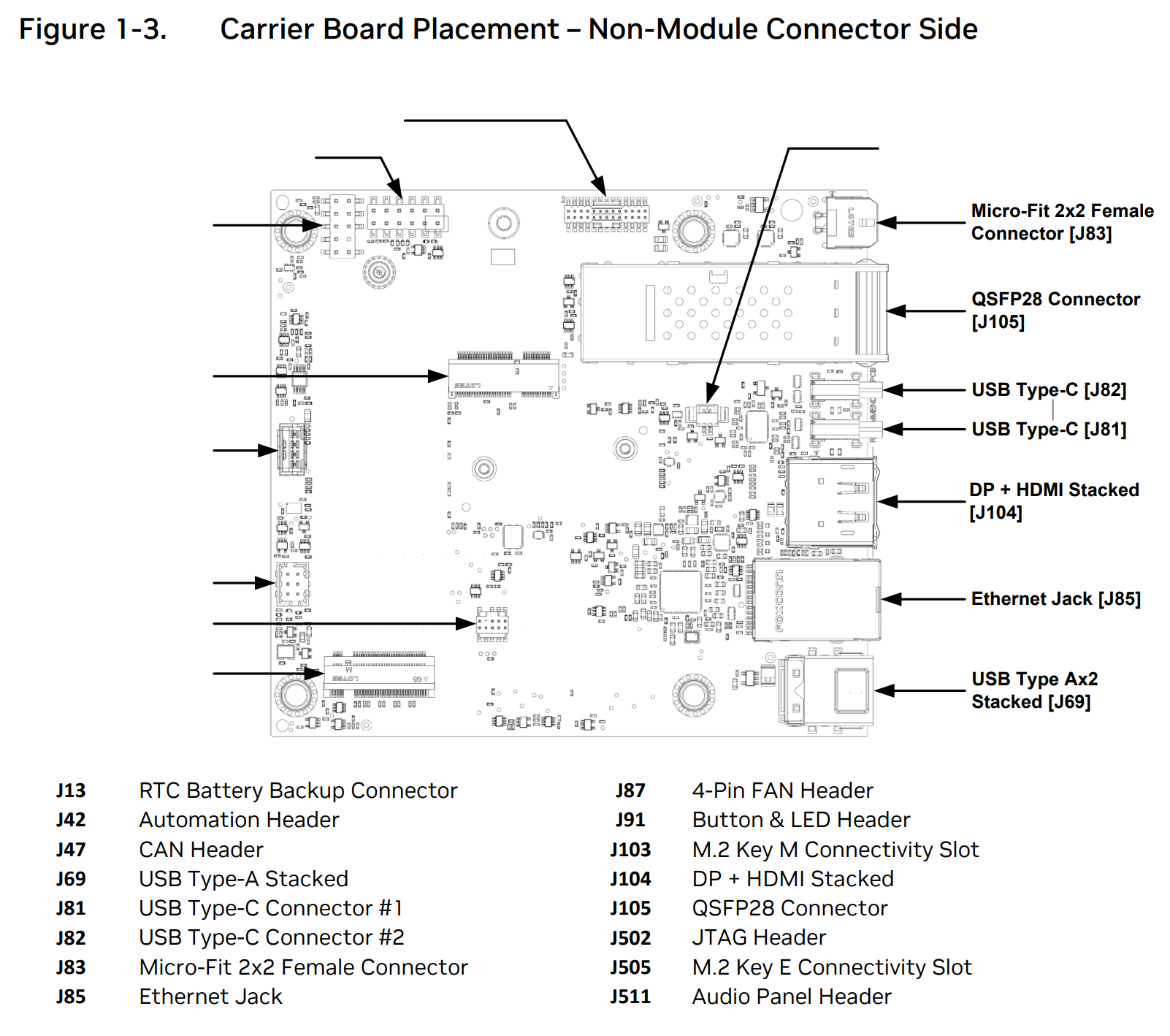
Non-Module Connector Side Layout#
Label |
Name |
Details |
|
|---|---|---|---|
J103 |
M.2 Key M Connectivity Slot |
1TB NVMe SSD pre-populated |