Jetson Xavier NX and Jetson AGX Xavier Boot Flow
Boot flow is the sequence of operations that the Bootloader performs initialize the SoC and boot NVIDIA® Jetson™ Linux. The major operations the bootloader performs are:
Initializing the memory controller (MC), external memory controller (EMC), and CPU
Setting up security parameters
Loading firmware components
Maintaining the chain of trust
Setting memory carveouts for various firmware components
Flashing the device
Booting to the operating system
Additionally, the Jetson boot software may perform other operations defined by product requirements, including but not limited to:
Initializing HDMI® or DisplayPort
Displaying a boot logo
The following diagram shows the flow of control in the boot software.

BootROM
BootROM (BR) is hard-wired into the processor. It initializes the boot media and loads Microboot1 (MB1) from it.
Multiple copies of the BootROM Boot Configuration Table* (BR-BCT) may be stored at the start of the boot media. The BR-BCT contains configuration parameters used by the BootROM for hardware initialization.
The BCT also contains information about the Bootloader (BL), including:
Size
Entry point
Load address
Hash
The BootROM uses this information to verify and load the Bootloader. The boot flow is shown in the following diagram.

Bootloader Components
The Bootloader and flash components are:
Microboot1 (MB1)
TBoot-BPMP
TBoot-CPU (used in flashing)
UEFI (kernel/OS loader used in cold boot)
Common Driver Framework
TBoot-BPMP and TBoot-CPU use a common set of drivers. Some libraries are common across the Bootloader components. Instead of using separate sets of drivers and libraries, the binaries share a common pool of drivers and libraries called the Common Driver Framework (CDF).
The following diagram shows the software architecture of the Common Driver Framework.

The Common Driver Framework consists of:
Storage drivers like eMMC, QSPI-NOR, mSATA, and UFS
Host interface drivers like UART, USB
Display drivers (HDMI, DP, and eDP)
Debug and Console library
Libraries of other modules such as:
Clock
SE
PMIC
Timer
Fuse
GPIO
PWM
EEPROM
Keyboard
PSCI
USB host mode (2.0 mode only)
USB host class drivers (only mass storage devices, no hub or HID support)
Software libraries such as:
Cryptographic
Transport
Partition manager
Sparse
Transport libraries
A decompression library that supports LZF, Zlib, and LZ4
clib, a dynamic memory allocation library, and a cache library
The CDF is provided at these locations:
<top>/vendor/nvidia/tegra/bootloader/partner/common/
<top>/vendor/nvidia/tegra/bootloader/partner/t18x/common/
Microboot1
Microboot1 (MB1) is the first boot software component loaded by BR in SysRAM, and runs on BPMP. This component implements certain platform initialization (including CPU) and security configuration.
MB1 is signed and encrypted by an NVIDIA-owned key. The following diagram shows the flow of control in MB1.

MB1 is responsible for:
Platform configuration, including pinmux, GPIO , pad voltage, SCRs, and firewalls
Initializing the SDRAM based on the MB1 boot configuration table (MB1-BCT)
Loading firmware, including the components that initialize the CPU complex (CCplex)
Programming the PMIC for enabling the VDD_CPU rail
Creating memory carveouts
Loading the next stage Bootloader, TBoot-BPMP
MB1 is owned by NVIDIA, and so is provided as a binary in the Jetson BSP package. Although it is provided as a binary, you can configure its behavior for a specific platform using its Boot Configuration Table, called MB1-BCT.
For information about the Boot Configuration Table, see MB1 BCT.
TegraBoot
TegraBoot is the Bootloader component that executes after MB1. It is divided into two components:
TBoot-BPMP
TBoot-CPU
The processor on which these parts run determines which component runs.
TegraBoot-BPMP
TegraBoot-BMP This portion of TegraBoot runs on BPMP (TBoot-BPMP). There are two variants of TegraBoot-BPMP:
One for cold boot
One for flashing and RCM (recovery) boot
TBoot-BPMP is responsible for:
Loading and initializing firmware (FW) components.
Creating memory carveouts
Restarting the CPU after it is halted
Loading the next stage Bootloader
Supporting flashing
Supporting RCM boot
The following diagram shows the components of TBoot-BPMP.

TegraBoot-CPU
TegraBoot-CPU runs on the CPU, and is responsible for:
Flashing
RCM boot
The RCM boot flow is similar to a cold boot except that the binaries are transferred from the host over USB, and are loaded directly into SDRAM. A trusted operating system (TOS) and BPMP-FW are not loaded in this path.
Note
The CPU starts execution in EL3 mode, and executes the TOS monitor. The TOS monitor completes its initialization and gives control to TegraBoot-CPU in EL2 mode. It then initializes the USB and starts the PPP (Point-to-Point Protocol) protocol to flash the device.
For normal flashing, TegraBoot-CPU takes binaries from the host one by one and flashes them to the device.
For RCM boot, TegraBoot-CPU takes binaries downloaded over USB. The binaries are not flashed to the device.
The following diagram shows the components of TBoot-CPU.

NVDisp-init
NVDisp-init runs on the CPU/CCPLEX, is derived from public CBoot source, and is only responsible for display HW init. NVDisp-init initializes the T194 display HW and chains/hands off to UEFI so that UEFI can copy a BMP file to the display framebuffer for the boot logo display. The NVDisp-init binary is bundled with the UEFI binary during flash, and MB2 loads it as the CPU-BL.
UEFI
Unified Extensible Firmware Interface (UEFI) is an industry specification that describes standard interfaces between platform firmware and the operating system. It replaces CBoot in the Jetson boot flow as the CPUBL for Jetson Linux devices.
Features of UEFI include:
Along with other specifications (SMBIOS, ACPI), it can load a generic OS without requiring any platform customization of the operating system.
It defines a standardized secure boot mechanism for authenticating third-party software (i.e. operating systems and PCIe option ROMs).
It supports add-in card drivers via option ROMs, and integrates them with the system configuration user interface.
It defines standard methods for updating firmware.
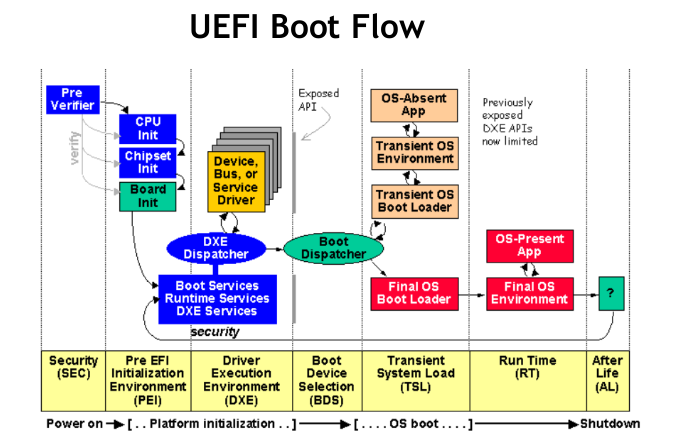
The following diagram describes the major aspects of UEFI boot flow.
UEFI sources and compilation details for this release are available at: https://github.com/NVIDIA/edk2-nvidia/wiki