Networking Planning and Design#
A NVIDIA team will have a network requirements gathering meeting with a SuperPOD customer directly to discuss network requirements and obtain the IP information. The following tables show the information that is needed in the planning stages:
Logical Network Design#
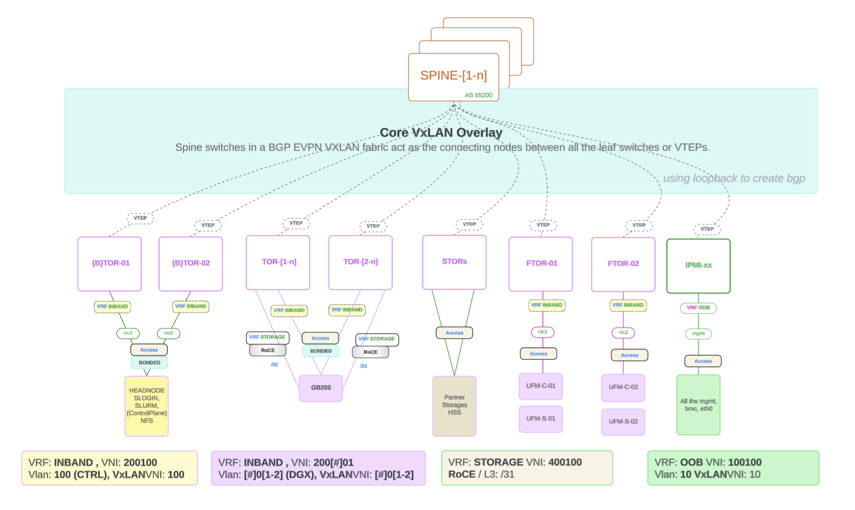
Figure 1 Logical Network Design Architecture (GB200; GB300 follows the same high-level design with subnetting differences; refer to Subnetting by DGX Model).#
Short Summary:
The following items provide a short summary of the logical network design:
BGP EVPN provides control plane signaling and tunnel discovery support in a VxLAN overlay network.
Loopback interfaces are commonly used for VTEPs (VXLAN Tunnel Endpoints) to establish BGP peering. Each VTEP is assigned a loopback IP address, which serves as a stable endpoint for routing EVPN control messages.
This approach enhances scalability and reliability, allowing for dynamic MAC address and IP address learning while maintaining tenant isolation. The VXLAN encapsulation enables seamless communication across the underlying network infrastructure, making it ideal for multi-tenant data centers and cloud environments.
Ethernet Networking (North-to-South)#
Reference: IP Subnet Range/CIDR Requirements per BCM Network
Network |
IP Range Requirement |
|---|---|
In Band Mgmt |
|
Out of Band (OOB) |
|
Loopback |
/24 - to cover address from each switch |
Client P2P IP Addressing (TOR to CE / Border TOR to EDGE Network) |
/31 - a minimum of 8 subnets |
Non-Routable IP Range |
|
ETH Storage Network |
100.127.0.0/16 |
IB Compute Network |
100.126.0.0/16 |
Vendor Storage Prefix |
100.127.124.0/24 |
Subnet Breakout per POD#
The following table shows the subnet breakout per POD:
POD |
OOB Total |
OOB Root |
DATA Total |
DATA Root |
ROOT |
|---|---|---|---|---|---|
1 |
2x/24 + 2x/23 |
/21 |
2x/23 + 2x/25 |
/21 |
/20 |
2 |
2x/24 + 4x/23 |
/20 |
4x/23 + 4x/25 |
/20 |
/19 |
3 |
1x/24 + 6x/23 |
/20 |
6x/23 + 6x/25 |
/20 |
/19 |
4 |
1x/24 + 8x/23 |
/19 |
8x/23 + 8x/25 |
/19 |
/18 |
5 |
1x/24 + 10x/23 |
/19 |
10x/23 + 10x/25 |
/19 |
/18 |
6 |
1x/24 + 12x/23 |
/19 |
12x/23 + 12x/25 |
/19 |
/17 |
7 |
1x/24 + 14x/23 |
/19 |
14x/23 + 14x/25 |
/18 |
/17 |
8 |
1x/24 + 16x/23 |
/18 |
16x/23 + 16x/25 |
/18 |
/17 |
Subnetting by DGX Model#
IP subnet allocation differs between GB200 and GB300. The table above is a general reference. For GB300 deployments, use the following hierarchy and VLAN layout.
GB300 IP subnetting (OOB and DATA):
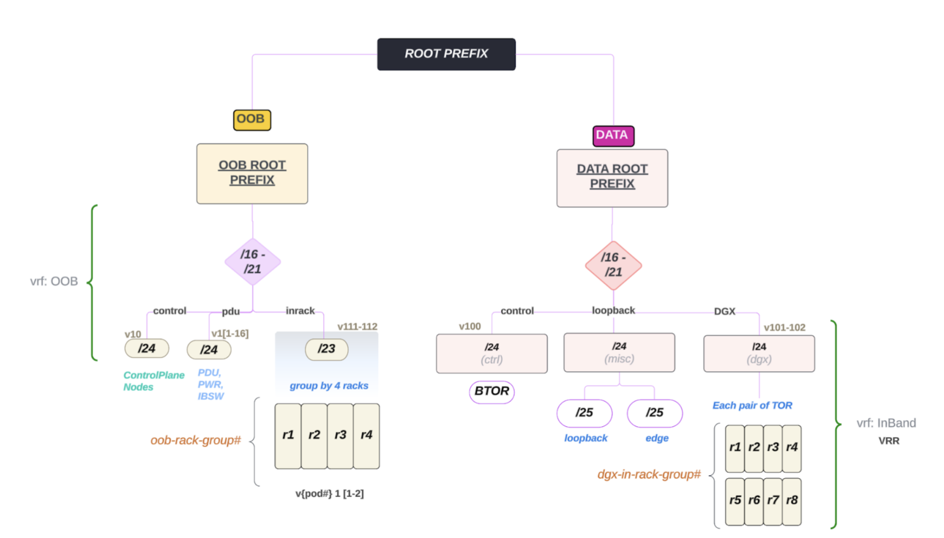
Figure 2 GB300 subnetting: ROOT PREFIX split into OOB (vrf OOB) and DATA (vrf InBand VRR), with control, PDU/inrack, and DGX segments.#
GB300 differences (summary):
OOB: control (v10 /24), PDU/PWR/IBSW (v1[1-16] /24), in-rack groups (v111-112 /23, group by 4 racks).
DATA: control/BTOR (v100 /24), loopback/misc (v101-102 /24, split into /25 loopback and /25 edge), DGX (v101-102 /24 dgx) with TOR pairs and dgx-in-rack groups (e.g. r1–r4, r5–r8).
Refer to the diagram for VLAN IDs and CIDR ranges when planning a GB300 deployment.
BGP ASN 4-Byte Range#
The following table shows the BGP ASN 4-byte range:
ROLES |
4-bytes ASN |
|---|---|
OOB |
429490**2361** - 429490**2460** |
TOR/STOR |
429490**2461** - 429490**2660** |
SPINEs |
429490**2661** - 429490**2750** |
SuperSPINEs |
429490**2751** - 429490**2760** |
Note
TOR to CE Transceiver Compatibility, refer to the Hardware Compatibility List (HCL)
We recommend that you review and refer to SuperPOD Network Requirements Document for more information.
Ethernet Planning#
Confirm Accurate Hardware Models and Quantities#
Confirm you have the accurate hardware models and correct amount. You can reference this list of items:
Ethernet switches x amount of SN5600
Transceivers (optical) and cables (DAC / AOC)
Fibers
Confirm You Have the Correct Cumulus Linux Software Version#
You need to ensure that you are using the correct version of the Linux distribution called Cumulus Linux.
Refer to DGX SuperPOD Documentation
Current Recommended Version -
v5.14.0
Obtain Customer Network Requirements#
You need to obtain the customer network requirements from the customer.
Fill out the “NVDA DGX SPOD GB200/GB300 Network Requirements” Excel file - Assuming in SIB
Content/Consideration List
Customer-Edge to Cluster connectivity
Transceiver type, compatibility and HW order status
Electrical signaling/encoding (NRZ vs PAM4)
Speed/Bandwidth
Uplink Quantity (transceiver, cable, fiber)
IP Addressing - P2P Uplinks
Routing protocol (default: BGP)
Routable IP Address Allocation
Discussed with and provided by the customer
Non-Routable IP Address Allocation
Use the default NVDA address ranges:
IB Compute =
100.126.0.0/16Ethernet Underlay =
10.254.0.0/16Ethernet Overlay Storage =
10.127.0.0/16
VLAN VNI Per TOR Pair
DGX Compute VLAN#
The following table shows the DGX Compute VLAN and VNI per POD:
POD# |
DGX Compute VLANs |
Compute VNI |
|---|---|---|
POD#1 |
101,102 |
101,102 |
POD#2 |
201,202 |
201,202 |
POD#3 |
301,302 |
301,302 |
POD#4 |
401,402 |
401,402 |
POD#5 |
501,502 |
501,502 |
POD#6 |
601,602 |
601,602 |
POD#7 |
701,702 |
701,702 |
POD#8 |
801,802 |
801,802 |
POD#9 |
901,902 |
901,902 |
POD#10 |
1001,1002 |
1001,1002 |
POD#11 |
1001,1002 |
1001,1002 |
POD#12 |
1201,1202 |
1201,1202 |
POD#13 |
1301,1302 |
1301,1302 |
POD#14 |
1401,1402 |
1401,1402 |
POD#15 |
1501,1502 |
1501,1502 |
POD#16 |
1601,1602 |
1601,1602 |
OOB VLAN / VNI#
The following table shows the OOB VLAN and VNI per POD:
POD# |
OOB VLAN |
Compute VNI |
|---|---|---|
POD#1 |
111,112 |
111,112 |
POD#2 |
221,222 |
221,222 |
POD#3 |
331,332 |
331,332 |
POD#4 |
441,442 |
441,442 |
POD#5 |
551,552 |
551,552 |
POD#6 |
661,662 |
661,662 |
POD#7 |
771,772 |
771,772 |
POD#8 |
881,882 |
881,882 |
POD#9 |
991,992 |
991,992 |
POD#10 |
1011,1012 |
1011,1012 |
POD#11 |
1111,1112 |
1111,1112 |
POD#12 |
1221,1222 |
1221,1222 |
POD#13 |
1331,1332 |
1331,1332 |
POD#14 |
1441,1442 |
1441,1442 |
POD#15 |
1551,1552 |
1551,1552 |
POD#16 |
1661,1662 |
1661,1662 |
The following shows the settings for VRF - VNI, VxLAN - VLAN ID, cluster route advertisement and external reachability, NVIS Deployment Preparation Information Requirements, and Point-to-Point Cabling Connectivity Plan.
VRF - VNI
OOB - 10010
Inband - 200100
Storage - 400100
VxLAN - VLAN ID
OOB - 1001
Inband - 2001
Cluster Route Advertisement and External Reachability
BMS Connectivity - Data Center Environment Monitoring
3rd Party Appliance Connectivity Requirements (Storage, etc.)
Physical Connectivity (Type, Speed, etc.)
Logical Connectivity (L2, Bond, L3, etc.)
IP Addressing
NVIS Deployment Preparation Information Requirements
MAC Address Collection of Devices (for DHCP) - “Factory File”
Host: BMC + N/S Provisioning Interfaces
Mgmt Servers (control plane)
DGX Servers (GB200/GB300)
UFM Servers
NetQ servers
Switch: Mgmt interface (mgmt. or eth0)
Ethernet
Infiniband
NVSwitch
PDUs: Mgmt interface (mgmt. or eth0)
“Factory File” Available from Manufacturing Partner
Includes component level MAC/Interface/SN/PN Information
DGX compute tray (GB200/GB300)
NVSwitch
MGX Rack Power Shelf
SN2201
Alternative: NVIS builds sheet with required information
Point-to-Point Cabling Connectivity Plan
Created and finalized in the SIB
Edge Network Handoff#
This section describes the Edge Network Handoff.
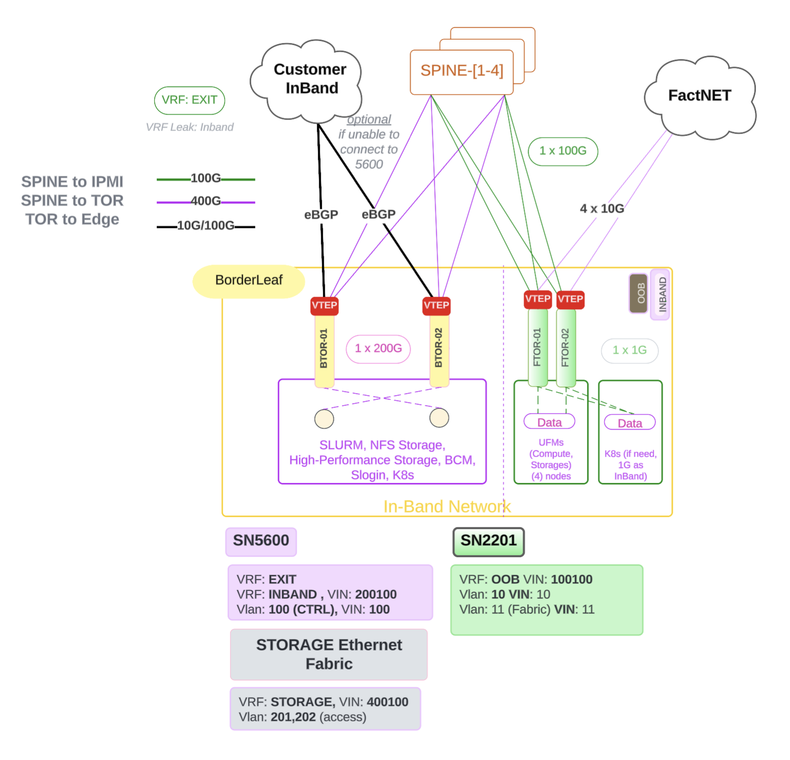
Figure 3 Edge Network Handoff#
Edge Network is the network that connects the SuperPOD to the customer’s network.
InBand and OOB Handoff Separation#
You can separate in-band and out-of-band (OOB) handoff to the customer by introducing an additional role called OOBSPINE. The OOBSPINE connects to the customer edge and receives a default route only into the OOB VRFs. This design allows you to leak routes through the BTOR (Border Leaf) for OOB connectivity while keeping in-band handoff and routing separate.
The following diagram shows the additional aggregated OOB handoff topology with the OOBSPINE role:
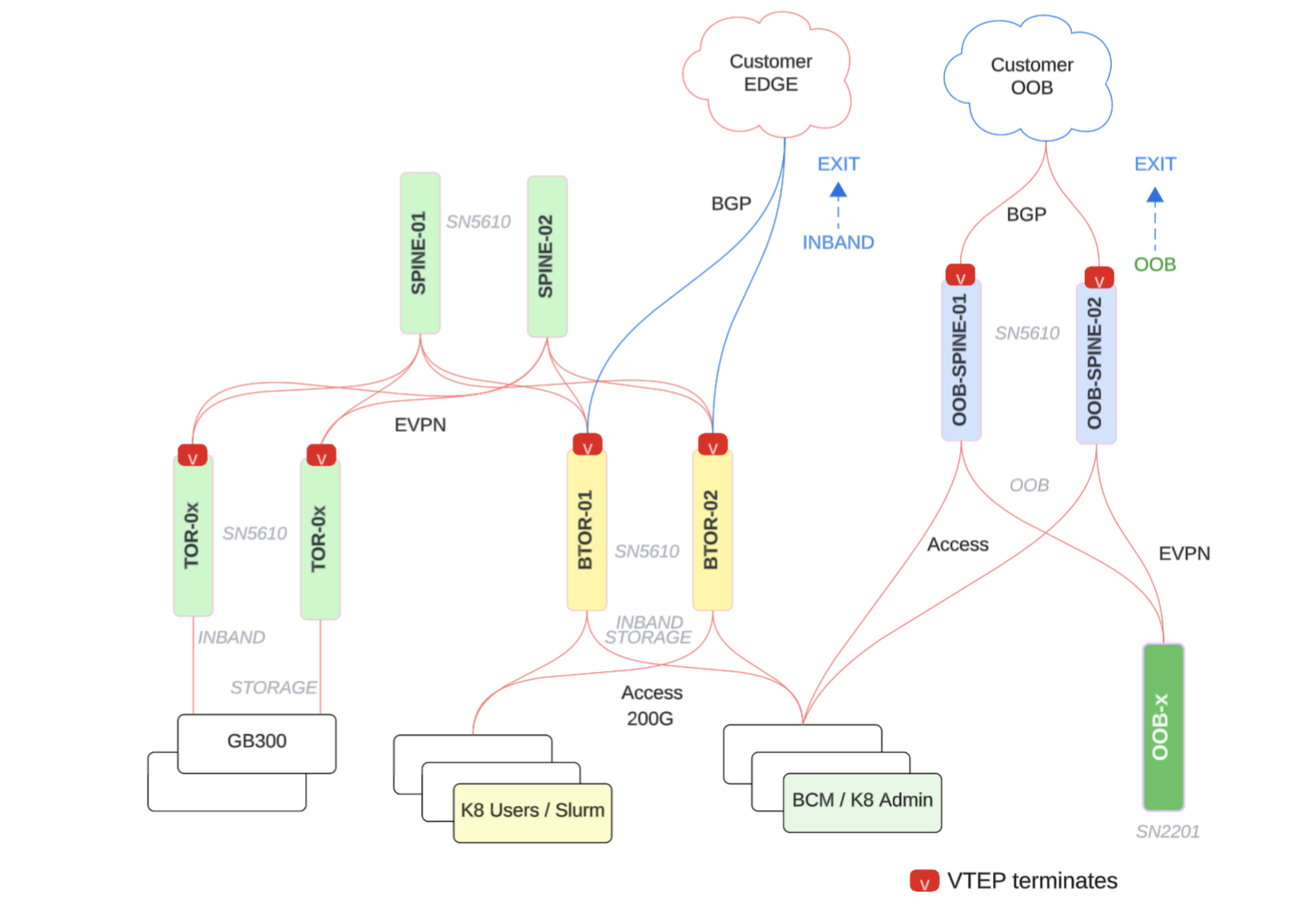
Figure 4 Additional aggregated OOB handoff: OOBSPINE connects to customer and receives default route only into OOB VRFs; routes can be leaked through BTOR (Border Leaf).#
The edge network is the network that connects the SuperPOD to the customer’s network and includes the following:
In-Band management for all ControlPlane mgmt and handoff routes.
VTEP on Leaf Switches: When VTEP functionality is terminated at the leaf layer, it means that leaf switches handle the encapsulation and decapsulation of VXLAN traffic. This reduces latency for traffic destined for or originating from the end hosts connected to the leaf switches.
eBGP between Border TOR and Customer Edge: Establish an external Border Gateway Protocol (eBGP) session between the border leaf switches (which connect the EVPN fabric to external networks) and the CE devices. This allows the SuperPOD to advertise routes to the customer’s network and receive routes from the customer’s network.