NVLink Switch Planning, Design, and Deployment Guide using Base Command Manager (BCM)#
This section provides an overview of the planning, design, and deployment process for NVLink Switch using the BCM.
NVLink Switch Planning#
When planning the NVLink Switch, you need to consider the following:
Hardware Components and Models#
Confirm you have the accurate hardware models and correct amount. You can reference this list of items:
Kubernetes Admin|User nodes Server - 3x
NVLink Switches (non-scaleout) - 9x per rack
Optical Transceivers and DAC/AOC cables
Fiber and Copper cables
Network and Connectivity Requirements#
The following are the key network and connectivity requirements to consider when planning your NVLink Switch deployment:
Kubernetes Admin|User nodes to BTOR switch connectivity
Transceiver type, compatibility and HW order status
Electrical signaling/encoding (NRZ vs PAM4)
Speed/Bandwidth
IP Addressing
Logical Connectivity (Access and Bonded)
NVLink Switch to OOB Switch connectivity
Copper connections
Speed/Bandwidth
IP Addressing
Logical Connectivity (Access)
Routable IP Address Allocation
Kubernetes Admin|User nodes server will have IP addresses allocated from Inband and OOB (ComE0) subnets.
NVLink Switches will have IP addresses allocated from OOB (ComE0) subnets.
Kubernetes Admin|User nodes and NVLink Switch Connectivity - To provision and manage NVLink Switch/NVLink.
Use the default partition.
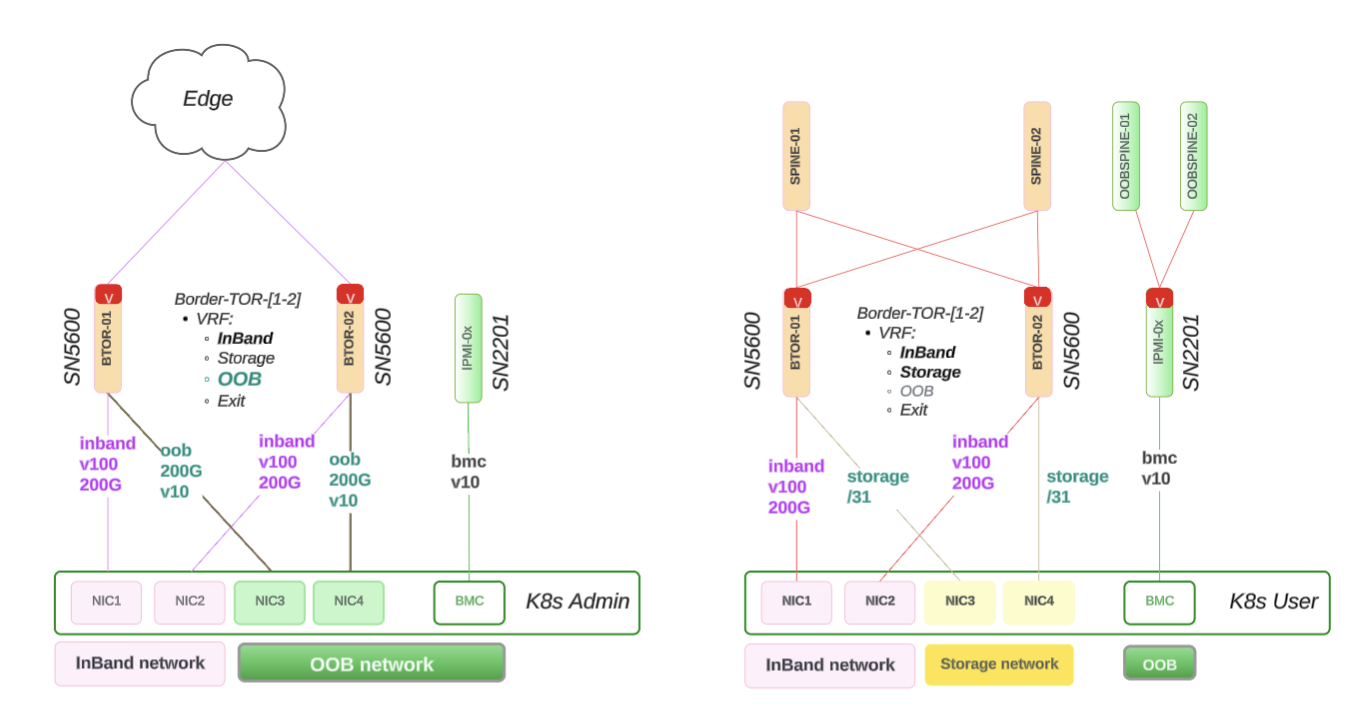
Figure 14 NVLink Switch Network Allocation Diagram#
NVLink Switch Design#
This section provides details on the NVLink Switch design, including:
Physical connectivity
NVLink Switch integration with BCM verification
The following diagram shows how the NVLink Switch connects to the Rack Switch using the NIC-COM ports and BMC on the OOB network.
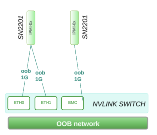
Physical Connectivity#
The following are the reference design for the NVLink Switch connectivity:
ComE1: 1G connects to within Rack Switch: SN2201 on RU 45
ComE2: 1G connects to within Rack Switch: SN2201 on RU 45
BMC: 1G connects to within Rack Switch: SN2201 on RU 44
Network Allocation Diagram#
This following network workflow diagram shows how the above ComE1, ComE2, and BMC are a part of the larger OOB subnet that covers 4 x DGX racks (GB200/GB300):
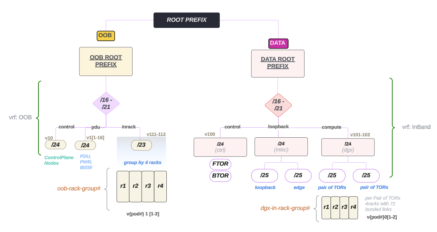
Figure 15 NVLink Switch Network Allocation Diagram#
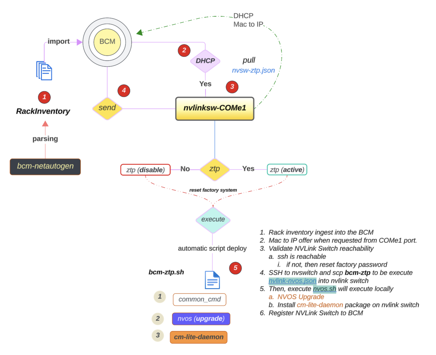
NVLink Switch Integration with BCM Verification#
The following image shows the workflow diagram of NVLink Switch integration with BCM:
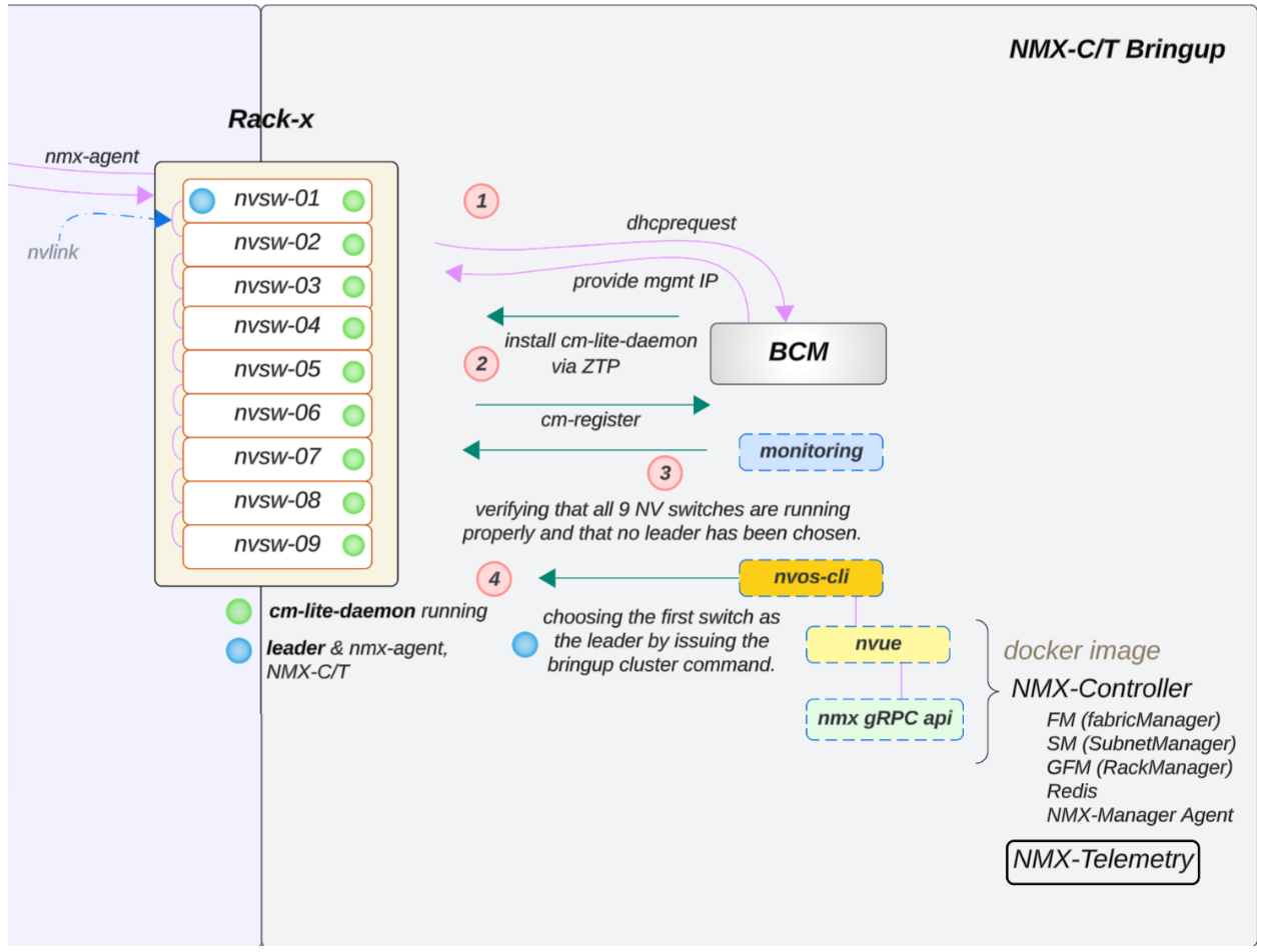
Figure 16 NVLink Switch Integration Workflow#
From the BCM, the following commands can be tested to validate the power control login works (using factory or default credentials):
power status
When the password is incorrect versus correct (using root/<password>; the password varies by factory), the output differs. The following shows a failed login (invalid credentials) and a successful login (power status [ ON ]):
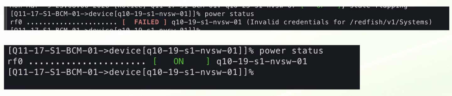
Figure 17 Power status: incorrect credentials (FAILED) vs correct credentials (ON).#
Additional notes:
Power reset — Reboots the switch but has no effect if the ZTP service is disabled.
ZTP disabled from the factory — ZTP is disabled because it was either successful (NVOS then disables the service) or was not used.
(Future) — An API call will be made to reset to factory default.
(Current) — Local script to reset to factory default:
nv action reset system factory-default force
Verify the NVLink Switch Configuration#
To verify that the NVLink Switch configuration is correct:
Confirm OOB power control of the NVLink Switches using a power status check in BCM, similar to what was done for a DGX compute tray (GB200/GB300).
Verify that an NVLink Switch can be reached through SSH from the head node using the admin user. The password may have been initially set during the bcm-netautogen (also known as netautogen) process. A typical password is admin.
ssh admin@<RACK_LOCATION>-NVSW-01Set the password to match what has been put into BCM for the NVLink Switch entry under accesssettings.
Verify that the following NVLink Switch parameters are set correctly:
NV configuration mode
NV configuration file
FM config file

Figure 18 NVLink Switch Parameter Settings#
Run the following command to verify the NVLink Switch parameters:
$ cmsh > device > use <NVLINK_SWITCH_NAME> ztpsettings
Updating the NVLink Switch to the Latest Firmware#
If the NVLink Switch is running a version earlier than v25.02.2134, the custom script and the cm-lite-daemon will not be installed.
However, once the NVLink Switch is upgraded to a newer version using ZTP, it will recognize the custom script option and install the cm-lite-daemon.
This process will take approximately 2-4 minutes longer than a standard ZTP.
The following flow diagram shows how the NVLink Switch is updated to the latest firmware:
To update the NVLink Switch to the latest version, you can use the following steps:#
If the NVLink Switch comes pre-installed with NVOS from the factory and the factory password has already been reset, NVOS Zero Touch Provisioning (ZTP) will be disabled.
The NVOS-ZTP script will be executed once the device is reachable.
Reset the NVLink Switch System to a factory reset.
Run the following command to reset the NVLink Switch System to a factory reset:
$ nv action reset system factory-default force
The NVLink Switch will reboot automatically (takes ~2.3mins)
Wait for the NVLink Switch to come back online.
On the backend, the following things will happen:
It will pull the nvlink-nvos.json file, validate the format, and create folders per section in
/var/lib/ztp/sections.It then executes each section one by one. For each section, it does the following:
Verifies network connectivity
Upgrades the NVOS image
Adjusts the security settings and disables password hardening
Applies the generated startup.yaml and patch configuration
Executes the nvos-ztp.sh script to install cm-lite-daemon, which does the following:
After the NVLink Switches are up and running within the rack, the system will automatically perform a Leader selection process
Out of 9, select 1 NVLink Switch:
Apply fm_config
Enable the cluster
Once the cluster is enabled, the NVLink Switch will be ready to use.