Unpacking and Physical Installation
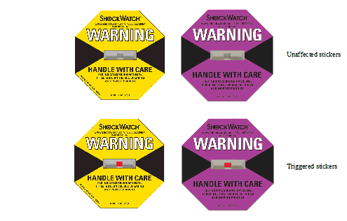
The crate has a shock sticker applied. When receiving the create, look for and inspect the shock sticker to confirm that it has not triggered.
IMPORTANT NOTE: The shock sticker does not necessarily indicate damage to the contents. However, be sure to carefully inspect the contents of a crate with a triggered sticker.
The shock stickers turn red if the create has been mishandled or handled roughly. If one of the shock stickers is red, notify the shipper and Mellanox.
Shock Stickers
Before starting the procedure, put the ESD strap on and connect it to a valid ground.
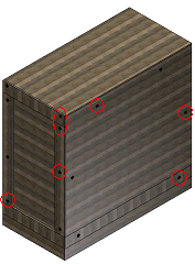
Unscrew and remove the top cover of the crate.
Unscrew and remove the sides of the crate.
TipIt is highly recommended to have a screw gun or electric screwdriver for this step.
Crate Screws
Remove the nylon covers from the chassis.
Visually inspect the chassis, make sure that:
There is no visible damage
6 PSUs are installed
Remove all protective plastic film from the sides and top of the chassis.
Unpack the system and check against the parts list to make sure that all the parts have been sent. Check the parts for visible damage that may have occurred during shipping. If anything is damaged or missing, contact your customer representative immediately.
Do not remove any of the blocks or the lock-down bars at this time.
The rack mounting holes conform to the EIA-310 standard for 19-inch racks. Guarantee proper ventilation, by leaving 8cm (3”) of space to the front and rear of the switch. This ensures proper airflow through the chassis. This is crucial for maintaining good airflow at ambient temperature. In particular, route cables such that they do not impede the air into or out of the chassis.
Warning: This equipment is very heavy. Make sure that adequate manpower and proper equipment is used for transporting and moving the chassis. Before attempting to move and place the chassis make sure that it is empty of all leafs, spines and management modules and to use a mechanical lift.
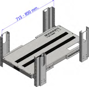
This chassis can be installed in standard 19” racks that have 715-850mm between the vertical supports of the rack.
Distance Between the Vertical Supports
The vertical supports may have to be moved so that the vertical support closest to the door is a minimum of 6cm from the inside of the door. This is required so that the shelf does not hit the door.
If you move the vertical supports make sure that you reinstall them vertically plumb.
The switch platform uses 17U of rack space, 16U for the chassis and 1U for the shelf. The switch ships from the factory with mounting holes on the spine side. There are upper brackets to connect the leaf side to the rack near the top of the chassis, and there are two lock-down bars to secure the chassis to the shelf. The weight of the switch is supported from underneath the unit by the shelf.
Due to the space required by up to 324 connector cables, it is recommended to use a rack that is 120cm long and 80cm wide. This should allow for proper cable management and enough ventilation to properly cool the chassis.
Before starting any procedure on the switch system:
Put an ESD prevention wrist strap on your wrist, and make sure there is good contact between your body and the strap.
Plug the other end of the wrist strap to a valid ground. Make sure that this is a tight fit.
You may need a mechanical lift to move and insert the chassis into the rack.
It is recommended to use an AWG6 or 4mm diameter wire for grounding purposes.
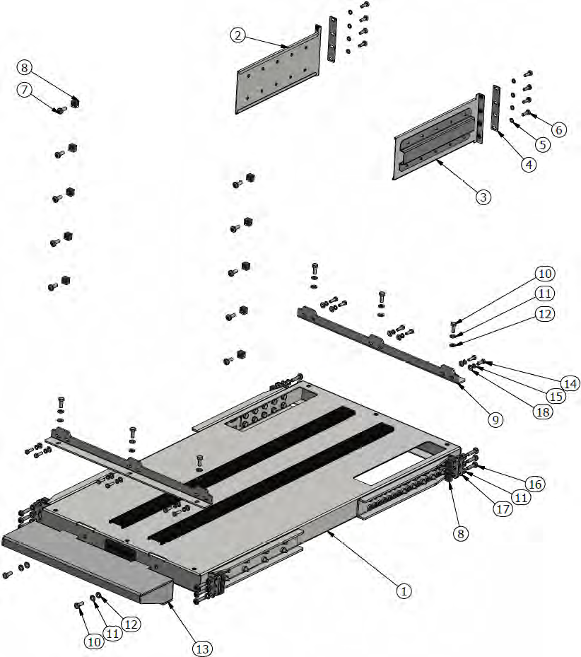
Chassis Installation Kit Items
|
Item No. |
Quantity |
Description |
Item No. |
Quantity |
Description |
|
1 |
1 |
Shelf assembly |
10 |
8 |
M6X16 hex-head screw |
|
2 |
1 |
Riveted right chassis slide |
11 |
20 |
M6 spring washer |
|
3 |
1 |
Riveted left chassis slide |
12 |
8 |
M6 flat washer |
|
4 |
2 |
Support bracket |
13 |
1 |
Weld bracket |
|
5 |
8 |
M5 spring washer |
14 |
12 |
10-32 hex-head screw |
|
6 |
8 |
M5 pan-head screw |
15 |
12 |
Spring washer #10 |
|
7 |
10 |
M6X16 pan-head screw |
16 |
12 |
M6X25 pan head screw |
|
8 |
22 |
M6 cage nut |
17 |
4 |
Shelf arm bracket |
|
9 |
2 |
Perforated fixing bracket |
18 |
12 |
Washer #10 |
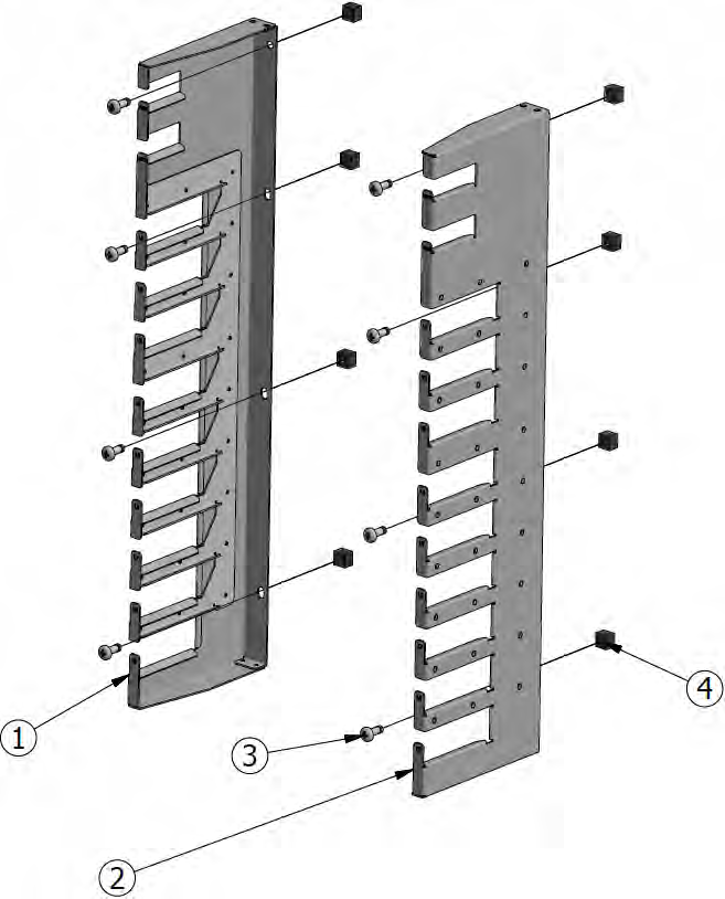
Cable Management Installation Kit Parts
|
Item No. |
Quantity |
Description |
Item No. |
Quantity |
Description |
|
1 |
1 |
Left riveted cable holder |
3 |
8 |
Pan head screw |
|
2 |
1 |
Right riveted cable holder |
4 |
8 |
M6 cage nut |
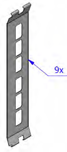
Shelf Installation Kit
The shelf installation kit includes 9 shelves only.
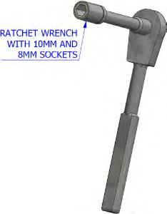
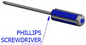
Required Installation Tools
Illustrated below are the tools which are required for the installation of the director switch chassis.
Some of the steps that follow are accompanied by figures that illustrate the installation of the switch system chassis. For the purpose of clarity, the racks in those figures will have the side panels removed. You, however, do not need to remove the side panels to install the switch chassis.
It is recommended to have at least three people for the duration of the installation procedure. Use a mechanical lift to raise this chassis. If not, use enough manpower to ensure the safety and wellbeing of all of the people involved in the installation.
Insert 3 M6 cage nuts each from the inside of BEAM-1 and BEAM-2 on the spine side in order to support the shelf.
TipIt is recommended to set the shelf at U3 since the chassis would roll off more easily on it from the pallet.
Cage Nut Placement for Shelf on BEAM-1 and BEAM-2


Insert 6 M6 cage nuts from the inside each of BEAM-3 and BEAM-4 on the leaf side in order to support the shelf.
Cage Nut Placement for Shelf on BEAM-3 and BEAM-4

Insert 5 M6 cage nuts (see Chassis Installation Kit Items) on the inside of each of the spine side beams of the rack in the slots. (The indexes in the figure below count from the first rack hole above the shelf.)
Cage Nut Placement for Switch System Chassis on Spine Side

Insert 4 M6 cage nuts (see Cable Management Installation Kit Parts) on the inside of each of the leaf side beams of the rack in the slots. (The indexes in the figure below count from the first rack hole above the shelf.)
Cage Nut Placement for Cable Holders on Leaf Side

Using a ratchet wrench, loosen the shelf arms’ M6 hex screws enough to allow for slight movement.
Loosening the Leaf-Side Shelf Arms
Adjust the shelf’s leaf-side arms so that the distance between the leaf-side and spine-side arms is at least 5mm longer than the distance between the rack beams.
Adjusting the Leaf-Side Shelf Arms
Place the shelf in U3 of the rack by inserting it at a tilt.
WarningAt least 2 people are necessary for installing the shelf.
Placing Shelf


Assemble the spine-side M6X25 pan-head screws and the arm brackets at an intermediate 3Nm torque.
Tightening Shelf Cage Nut Screws on Spine Side


Assemble the leaf-side M6X25 pan-head screws and the arm brackets at 3Nm torque.
Tightening Shelf Cage Nut Screws on Leaf Side
Tighten the M6X25 pan-head screws of the shelf arms on the spine side at 9Nm torque.
Tightening Spine-side Shelf Arm Screws
Tighten the 10 hex head screws of the shelf’s leaf-side arms at 9Nm torque on both sides.
Tightening Spine-side Shelf Arm Screws
Tighten the 6 M6X25 pan-head screws of the shelf’s leaf-side arms at 9Nm torque now that the shelf has been placed.
Tightening Leaf-side Shelf Screws
Assemble the bracket weld to the shelf on the spine side and tighten at 5Nm with 2 hex screws, 2 spring washers and 2 flat washers.
Weld Bracket Assembly


Before placing the chassis in the rack, make sure to leave more room on the leaf (port cables) side to allow room for cable management.
Placement of Chassis in Rack – Top View
Put the crate on the fork lift or a mechanical lift.
WarningFor Steps 15-22, three people should participate in the installation process.
Fork Lift

Mechanical Lift

Position the chassis in front of the installation rack.
Unscrew both lock-down bars.
ImportantThe chassis is on ball bearings and can roll easily. Beware that the chassis can roll off of the pallet possibly causing grave bodily harm should it fall on someone.
Using a fork or mechanical lift, position the middle of the leaf-side of the chassis in front of the spine-side of the rack.
Rack and Chassis Alignment
Place the rotated strip on top of the bracket weld.
Rotated Strip and Bracket Weld
Unscrew the lock-down bar facing the rack.
ImportantNote that the chassis is on ball bearings, and with the lock-down bars removed, the chassis can roll off!
Slide the switch system chassis halfway into the rack.
ImportantPush only from the spine side so as to not injure your fingers during insertion.
Sliding Chassis in Rack

Slide the switch system chassis all the way into the rack until it stops.
ImportantBeware not to injure your fingers during insertion.
Slide in the left and right chassis slides from the leaf side.
Sliding in Chassis Slides

Slide the switch system chassis all the way into the rack.
Sliding Chassis into Rack
Screw the chassis to the rack on the spine side using 10 M6X16 screws where the cage nuts have been placed at 9Nm torque.
Remove the bracket weld on the spine side.
Screwing the Chassis to the Rack

Assemble the 2 4-oval washer plates to the left and right chassis slides on the leaf side at 3.23-3.58Nm torque using 4 M5 pan-head screws on each side.
Screwing the 4-Oval Washer Plates


Remove the M6X16 screws holding the weld bracket on the spine side using a ratchet wrench.
Removing the Weld Bracket
Place the perforated fixing bracket on the shelf from the leaf side and assemble it using a ratchet wrench (with 8mm socket) and 6 10-32 hex screws, 6 #10 flat washers, and 6 #10 spring washers to the chassis at 3.23-3.58Nm torque.
Leaf Side Fixing Bracket With Chassis


Place the perforated fixing bracket on the shelf from the spine side and assemble it using 6 10-32 hex screws, 6 #10 spring washers, and 6 #10 flat washers to the chassis at 3.23-3.58Nm torque.
Spine Side Fixing Bracket With Chassis

Screw the perforated fixing bracket on the leaf side to the shelf at 9Nm torque.
Leaf Side Fixing Bracket With Shelf


Screw the fixing bracket on the spine side to the shelf using 3 M6X16 hex screws, 3 M6 spring washers, and 3 M6 flat washers at 9Nm torque.
Spine Side Fixing Bracket With Shelf

Assemble the cable holders to the leaf-side rack using 8 M6X16 pan-head screws at 9Nm torque.
Installing Cable Holders
