Hardware Installation
Installation and initialization of ConnectX-5 adapter cards require attention to the mechanical attributes, power specifications, and precautions for electronic equipment.
Safety warnings are provided here in the English language. For safety warnings in other languages, refer to the Adapter Installation Safety Instructions.
Please observe all safety warnings to avoid injury and prevent damage to system components. Note that not all warnings are relevant to all models.
Note that not all warnings are relevant to all models.

| General Installation Instructions |

| Jewelry Removal Warning |
|
| Over-temperature |
|
| During Lightning - Electrical Hazard |
|
| Copper Cable Connecting/Disconnecting |
|
| Equipment Installation |
|
| Equipment Disposal |
|
| Local and National Electrical Codes |

| Hazardous Radiation Exposure
|
The installation procedure of ConnectX-5 adapter card kit with Multi-Host involves the following steps:
Step | Procedure |
1 | Check the system’s hardware and software requirements. |
2 | Pay attention to the airflow consideration within the host system. |
3 | Unpack the product. |
4 | Install the ConnectX-5 main adapter card in the system. |
5 | Install the PCIe Auxiliary cards in the system. |
6 | Connect the mini SAS harnesses or modules to the card. |
7 | Power Up the card |
8 | Identify your ConnectX-5 adapter card in the system. |
Hardware Requirements
Unless otherwise specified, NVIDIA products are designed to work in an environmentally controlled data center with low levels of gaseous and dust (particulate) contamination.
The operating environment should meet severity level G1 as per ISA 71.04 for gaseous contamination and ISO 14644-1 class 8 for cleanliness level.
A system with four available PCI Express x4 slots is required for installing the ConnectX-5 and card and three PCIe Auxiliary cards.
For proper operation and performance, please make sure to use a PCIe slot with a corresponding bus width and that can supply sufficient power to your card. Refer to the Specifications section of the manual for more power requirements.
Airflow Requirements
ConnectX-5 adapter card kit is offered with one airflow pattern: from the network ports to the heatsink, as shown below.
Please refer to the "Specifications" chapter for airflow numbers.
Airflow from the network ports to the heatsink:
All cards in the system should be planned with the same airflow direction.
Software Requirements
See Operating Systems/Distributions section under the Introduction section.
Software Stacks - NVIDIA OpenFabric software package MLNX_OFED for Linux. See the Driver Installation section.
The adapter is being installed in a system that operates with voltages that can be lethal. Before opening the case of the system, observe the following precautions to avoid injury and prevent damage to system components.
Remove any metallic objects from your hands and wrists.
Make sure to use only insulated tools.
Verify that the system is powered off and is unplugged.
It is strongly recommended to use an ESD strap or other antistatic devices.
Unpack the adapter package and place them on an antistatic surface, and verify you have received the following items:
ConnectX-5 Adapter Card, with a short bracket assembled on the card.
3x PCIe Auxiliary cards, with a short bracket assembled on each of the cards.
3x Mini-SAS HD cables.
Check the parts for visible damage that may have occurred during shipping.
Shut down your system if active:
Turn off the power to the system, and disconnect the power cord. Refer to the system documentation for instructions. Before you install the ConnectX-5 card, make sure that the system is disconnected from power.
This section provides detailed instructions on how to install your ConnectX-5 adapter card kit in your system.
Please note that the following figures are for illustration purposes only.
The ConnectX-5 VPI adapter card kit installation in the system should be planned according to the below figure.
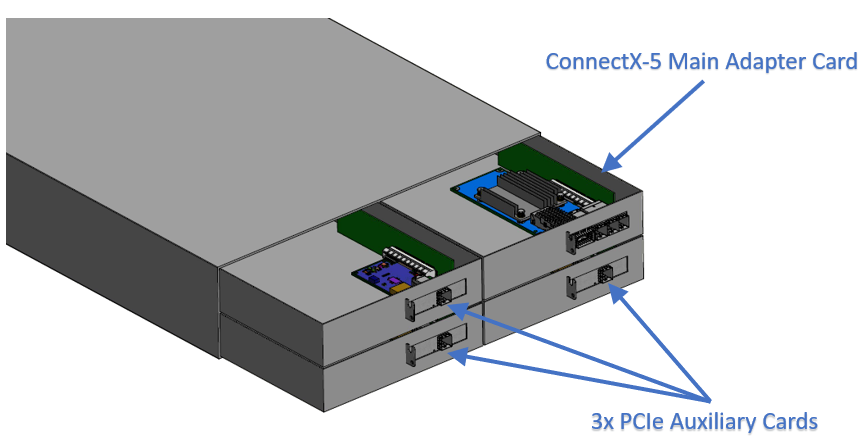
Install the ConnectX-5 main adapter card in the system:
Before installing the card, make sure that the system is off and the power cord is not connected to the server. Please follow proper electrical grounding procedures.
Open the system case.
Applying even pressure at both corners of the card, insert the card into the PCI Express slot until firmly seated.

When the adapter is properly seated, the port connectors are aligned with the slot opening, and the adapter faceplate is visible against the system chassis.

Secure the adapter with the adapter screw.
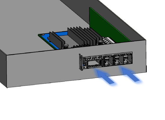
Install the three PCIe Auxiliary cards in the system:
Applying even pressure at both corners of the card, insert the PCIe Auxiliary cards into the available PCI Express x4 slots until firmly seated.

When the PCIe Auxiliary card is properly seated, the harness connector is aligned with the slot opening, and the PCIe Auxiliary faceplate is visible against the system chassis.

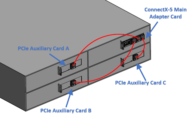
Connect the ConnectX-5 Main Adapter Card with each PCIe Auxiliary Cards using the supplied mini SAS harnesses, as shown in the below figure.
Connect the ConnectX-5 Main Adapter Card with each PCIe Auxiliary Cards using the supplied mini SAS harnesses, as shown in the below figure.
To uninstall the adapter card, see Uninstalling the Card.
Cable Installation
All cables can be inserted or removed with the unit powered on.
To insert a cable, press the connector into the port receptacle until the connector is firmly seated.
Support the weight of the cable before connecting the cable to the adapter card. Do this by using a cable holder or tying the cable to the rack.
Determine the correct orientation of the connector to the card before inserting the connector. Do not try and insert the connector upside down. This may damage the adapter card.
Insert the connector into the adapter card. Be careful to insert the connector straight into the cage. Do not apply any torque, up or down, to the connector cage in the adapter card.
Make sure that the connector locks in place.
WarningWhen installing cables make sure that the latches engage.
ImportantAlways install and remove cables by pushing or pulling the cable and connector in a straight line with the card.
After inserting a cable into a port, the Green LED indicator will light when the physical connection is established (that is, when the unit is powered on and a cable is plugged into the port with the other end of the connector plugged into a functioning port). See Adapter Card LED Operations.
After plugging in a cable, lock the connector using the latching mechanism particular to the cable vendor. hen data is being transferred the Green LED will blink. See Adapter Card LED Operations under the Interfaces section.
Care should be taken as not to impede the air exhaust flow through the ventilation holes. Use cable lengths which allow for routing horizontally around to the side of the chassis before bending upward or downward in the rack.
To remove a cable, disengage the locks and slowly pull the connector away from the port receptacle. LED indicator will turn off when the cable is unseated.
Power up the ConnectX-5 main board, and then, power up the PCIe Auxiliary Cards.
Powering up the auxiliary cards while the main card is not power up may cause serious damage to the cards.
In power down, power down the PCIe auxiliary cards and then the ConnectX-5 card main card.
On Linux
Get the device location on the PCI bus by running lspci and locating lines with the string “NVIDIA Technologies”:
            lspci |grep -i NVIDIA
Network controller: NVIDIA Technologies MT28800 Family [ConnectX-5]
On Windows
Open Device Manager on the server. Click Start => Run, and then enter devmgmt.msc.
Expand System Devices and locate your NVIDIA ConnectX-5 adapter card.
Right click the mouse on your adapter's row and select Properties to display the adapter card properties window.
Click the Details tab and select Hardware Ids (Windows 2012/R2/2016) from the Property pull-down menu.
PCI Device (Example)

In the Value display box, check the fields VEN and DEV (fields are separated by ‘&’). In the display example above, notice the sub-string “PCI\VEN_15B3&DEV_1003”: VEN is equal to 0x15B3 – this is the Vendor ID of NVIDIA Technologies; and DEV is equal to 1018 (for ConnectX-5) – this is a valid NVIDIA Technologies PCI Device ID.
WarningIf the PCI device does not have a NVIDIA adapter ID, return to Step 2 to check another device.
WarningThe list of NVIDIA PCI Device IDs can be found at the PCI ID repository.