Interfaces
The below figures show the component side of the NVIDIA ConnectX-6 Dx adapter card. Each numbered interface referenced in the figure is described in the following table with a link to detailed information.
The ConnectX-6 Dx adapter card includes special circuits to protect from ESD shocks to the card/server when plugging copper cables.
The below figures are for illustration purposes only and might not reflect the current revision of the adapter card.
NVIDIA ConenctX-6 Dx for OCP 3.0 Adapter Card Interfaces - Component Side
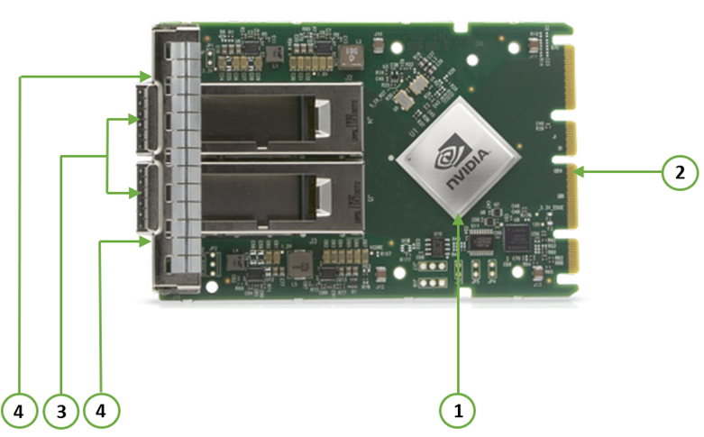
Callout | Item | Description |
1 | NVIDIA ConnectX-6 Dx IC on the board. | |
2 | PCIe Gen 3.0/4.0 through an x16 edge connector. | |
3 | Ethernet traffic is transmitted through the adapter's SFP28/SFP56/QSFP56 connectors. The networking connectors allow for the use of modules, optical and passive cable interconnect solutions. | |
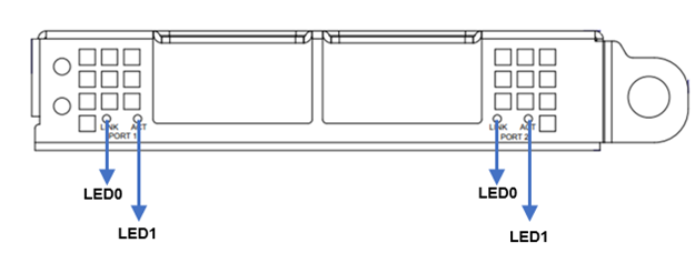
4 | There are two I/O LEDs, LED0 and LED1, per port to indicate speed and link status. | |
FRU EEPROM capacity 4Kb | ||
Allows BMC connectivity using MCTP over SMBus or MCTP over PCIe protocols. | ||
Voltage supply pins that feed onboard regulators. | ||
Controls the networking port LEDs. |
The ConnectX®-6 Dx EN family of adapter IC devices delivers two ports of 10/25/40/50/100Gb/s or a single port of 200Gb/s Ethernet connectivity paired with best-in-class hardware capabilities that accelerate and secure cloud and data-center workloads.
Encryption
Applies to Crypto-enabled OPNs.
ConnectX-6 Dx brings security to every end-point, including:
Purpose-built inline acceleration engines that offload IPsec and TLS data-in-motion and XTS-AES data-at-rest cryptographic operations.
Stateful firewall solution acceleration, powered by Open vSwitch connection tracking and NVIDIA's ASAP2 technology.
Embedded hardware root-of-trust and support for RSA-based secure firmware update and secure boot, guaranteeing the network adapter's integrity.
NVIDIA Multi-HostTM Support
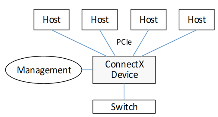
In addition to building exceptionally high bandwidth to the data center, the ConnectX-6 Dx device enables leveraging this speed across the entire data center utilizing its NVIDIA Multi-Host feature.
Using its 32-lane PCI Express interface, a single ConnectX-6 Dx device can provide 200GbE interconnect for up to four independent hosts without any performance degradation.
The figure below shows a ConnectX-6 Dx device with NVIDIA Multi-Host connected to four separate hosts, each with a PCIe x4 interface, on one side to a switch on the other side.
The below bifurcation are optional for the adapter's x16 PCIe interface:
x1 PCIe x16, x1 PCIe x8, x1 PCIe x4
x2 PCIe x8, x2 PCIe x4, x2 PCIe x2, x2 PCIe x1
x4 PCIe x4, x4 PCIe x2, x4 PCIe x1
Multi-host capable cards also support Socket-Direct applications and work as regular Single-Host cards, depending on the type of server they are plugged into, assuming the server complies with the OCP 3.0 spec.
According to the OCP 3.0 spec, the adapter card advertises its capability through the PRSNTB[3:0]# pins. The server determines the configuration through the BIF[2:0]# pins, which it drives to the adapter card.
The NVIDIA OCP3.0 card has an internal logic that uses the BIF[2:0]# data and determines the correct operating mode to boot at. The combination of the PRSNTB[3:0]# and BIF[2:0]# pins deterministically sets the PCIe lane width for a given combination of OCP 3.0 cards and baseboard. The logic and the decoding table can be found in the OCP 3.0 spec (Chapter 3.5 PCIe Bifurcation Mechanism.
For example:
the NVIDIA OCP 3.0 Multi-host adapter drives 0100 on PRSNTB[3:0]# to the server.
If Server Drivers | Adapter PCIe Mode |
000 | Single-Host Mode: x1 PCIe x16 |
001 | Socket Direct Mode: x2 PCIe x8 |
010 | Socket Direct Mode: x4 PCIe x4 |
101 | Multi-Host Mode: x2 PCIe x8 |
110 | Multi-Host Mode: x4 PCIe x4 |
The network ports of the ConnectX®-6 Dx adapter card are compliant with the IEEE 802.3 Ethernet standards listed in Features and Benefits. Ethernet traffic is transmitted through the networking connectors on the adapter card.
The adapter card includes special circuits to protect from ESD shocks to the card/server when plugging copper cables.
The table below describes the supported PCIe interface in ConnectX®-6 Dx adapter cards.
Supported PCIe Interface | Features |
PCIe Gen 3.0/4.0 (1.1 and 2.0 compatible) through x16 edge connectors | Link Rates: 2.5. 5.0, 8.0 or 16GT/s. Auto Negotiation to: x16, x8, x4, x2 or x1. Support for MSI/MSI-X mechanisms. |
There are two I/O LEDs, LED0 and LED1, per port to indicate speed and link status. LED0 is a bicolor (yellow and green) LED, and LED1 is a single color (green) LED.
Link Indications
LED and State | Description | |||||||||
1Hz blinking Yellow | Beacon command for locating the adapter card | |||||||||
4Hz blinking Yellow | Indicates an error with the link. The error can be one of the following:
| |||||||||
LED0 - Link Speed |
| |||||||||
LED1 - Activity |
|
FRU EEPROM
FRU EEPROM allows the baseboard to identify different types of Mezzanine cards. FRU EEPROM is accessible through SMCLK and SMDATA. FRU EEPROM address is defined according to SLOT_ID0 and SLOT_ID1, and its capacity is 4Kb.
ConnectX®-6 Dx technology maintains support for manageability through a BMC. ConnectX®-6 Dx OCP 3.0 adapter can be connected to a BMC using MCTP over SMBus or MCTP over PCIe protocols as if it is a standard NVIDIA OCP 3.0 adapter. For configuring the adapter for the server's specific manageability solution, please contact NVIDIA Support.
The voltage regulator power is derived from the OCP 3.0 edge connector 12V and 3.3V supply pins. These voltage supply pins feed onboard regulators that provide the necessary power to the various components on the card.
The adapter card incorporates a CPLD device that controls the networking port LEDs and the scan chain. It draws its power supply from 3.3V_EDGE.
A heatsink is attached to the ConnectX®-6 Dx IC to dissipate the heat. It is connected by four spring-loaded push pins that insert into four mounting holes.
ConnectX®-6 Dx IC has a thermal shutdown safety mechanism that automatically shuts down the ConnectX®-6 Dx card in case of a high-temperature event, improper thermal coupling, or heatsink removal.