Remote Access to NVIDIA Devices
In order to update MT52000 Switch-IB device with a specific GUID (for example, 0xe41d2d03001094b0) using In-Band, the following steps are recommended:
For Linux device names should be listed with the /dev/mst prefix. For Windows, no prefix is required.
Make sure all subnet ports are in the active state. One way to check this is to run opensm, the Subnet Manager.
[root
@mymach]> /etc/init.d/opensmd start opensm start [ OK ]Make sure the local ports are active by running ‘ibv_devinfo’.
Obtain the device LID. There are two ways to obtain it:
Using the “mst ib add” command:
The “mst ib add”runs the ibdiagnet/ibnetdiscover tool to discover the InfiniBand fabric and then lists the discovered IB nodes as an mst device. These devices can be used for access by other MFT tools.
[root
@mymach]> mst ib add -I- Discovering the fabric - Running: /opt/bin/ibdiagnet -skip all -I- Added3in-band devicesTo list the discovered mst inband devices run “mst status”.
devices[root
@mymach]> mst status MST modules: ------------ MST PCI module loaded MST PCI configuration module loaded ... Inband devices: ------------------- /dev/mst/CA_MT4103_sw005_HCA-1_lid-0x0001/dev/mst/CA_MT4115_sw005_HCA-2_lid-0x0002/dev/mst/SW_MT52000_lid-0x0010[root@mymach]>Using the ibnetdiscover tool, run:
ibnetdiscover | grep e41d2d03001094b0 | grep -w Switch Switch
36"S-e41d2d03001094b0"#"SwitchIB Mellanox Technologies"enhanced port0lid16lmc0WarningThe resulting LID is given as a decimal number.
Run mlxburn with the LID retrieved in Step 3 above to perform the In-Band burning operation.
Burn the Switch-INB device:# mlxburn -d lid-
0x0010-fw ./fw-SwitchIB.mlx -I- Querying device ... -I- Using auto detected configuration file: ./MSB7700-E_Ax.ini (PSID = MT_1870110032) -I- Generating image ... Current FW version on flash:11.0.1250New FW version:11.0200.0120Burning FS3 FW image without signatures - OK Restoring signature - OK -I- Image burn completed successfully.
In most cases, an adapter is connected to a single InfiniBand subnet. The LIDs (InfiniBand Local IDs) on this subnet are unique. In this state, the device access MADs are sent (to the target LID) from the first active port on the first adapter on the machine.
In case that the different IB ports are connected to different IB subnets, source IB port on the local host should be specified explicitly.
The device name would be in the format:
<any-string>lid-<lid-number>[,source adapter name][,source IB port number]
For example:
On Linux: lid-3,mlx4_0,1
On Windows: lid-3,0,1
Say we have the following setup:
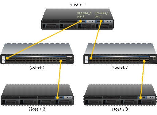
H1 host has 2 adapters. Port 1 of the first adapter is connected to Switch 1, and port 2 of the second adapter is connected to Switch 2. Since the 2 adapters on the H1 are not connected to the each other, there are 2 separate IB subnets in this setup.
Subnet1 nodes: H1 Switch 1 and H2 Subnet2 nodes: H1 Switch 2 and H3
Running "ibv_devinfo" command on H1 would list the 2 adapter names. For ConnectX adapters, the names would be mlx4_0 and mlx4_1.
Running "mst ib add" would add ib devices from the default port (first active port on the first adapter) - only Subnet1 nodes would be listed.
To add the nodes of the second subnet, the source adapter and port should be specified to the "mst ib add" command in the following format:
# mst ib add <hca_name> <hca_port>
Examples:
Add nodes of both subnets, Run:
            # mst ib add mlx4_0 1
# mst ib add mlx4_1 2
List the devices:
            # mst status
...
/dev/mst/CA_MT25418_H1_HCA-1_lid-0x0001,mlx4_0,1
/dev/mst/CA_MT25418_H2_HCA-1_lid-0x0005,mlx4_0,1
/dev/mst/SW_MT51000_Switch1_lid-0x0003,mlx4_0,1
/dev/mst/CA_MT25418_H1_HCA-1_lid-0x0010,mlx4_1,2
/dev/mst/CA_MT25418_H3_HCA-1_lid-0x0012,mlx4_1,2
/dev/mst/SW_MT51000_Switch2_lid-0x0005,mlx4_1,2
You can use the above device names with the MFT tools.
The MTUSB-1 is a USB to I2C bus adapter. This chapter provides the user with hardware and software installation instructions on machines running Linux or Windows operating systems.
MTUSB-1 Device
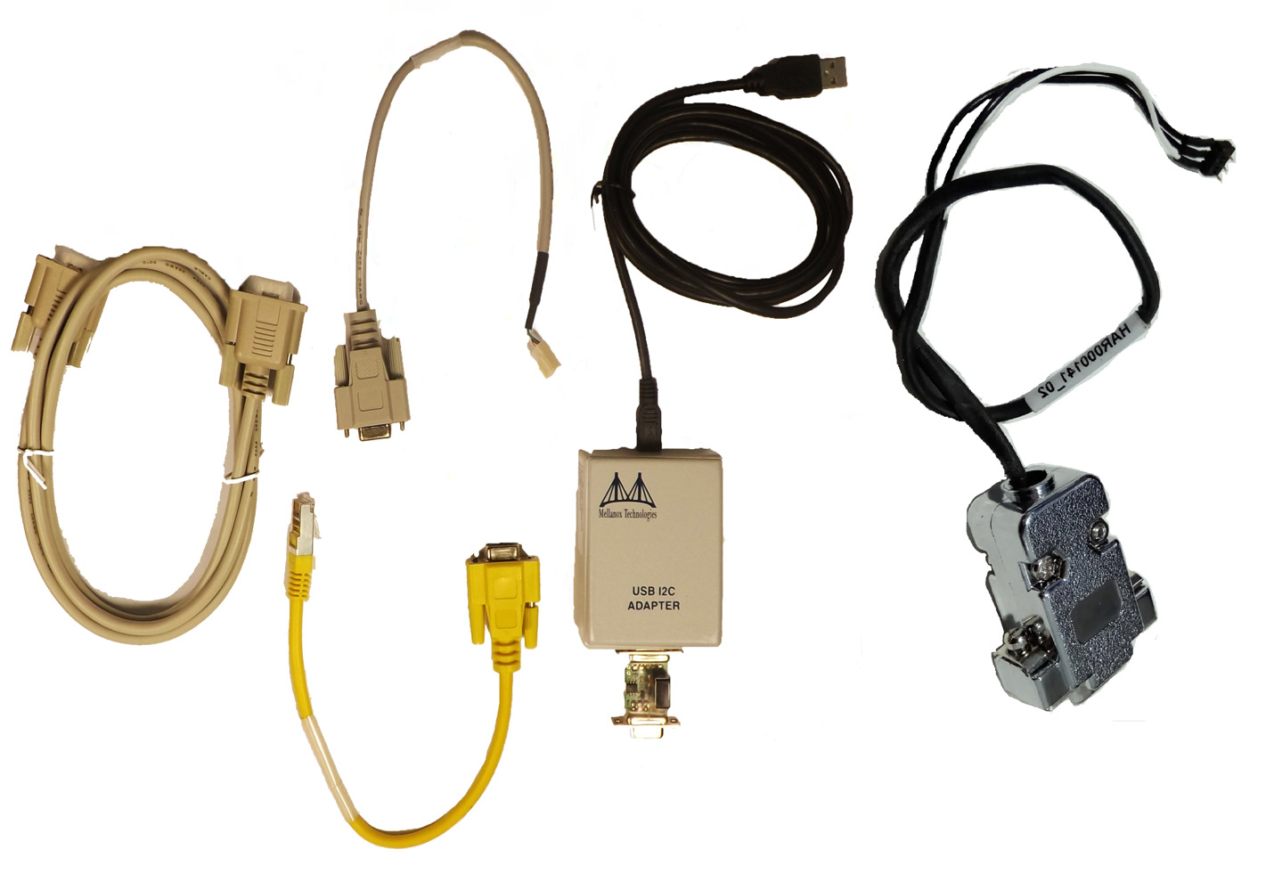
MTUSB-1 Package Contents
Please make sure that your package contains the items listed and that they are in good condition.
|
Item |
Quantity |
Description |
|
MTUSB-1 device |
1 |
USB to I2C bus adapter |
|
USB cable |
1 |
USB_A to USB_B (1.8m) |
|
I2C cable |
1 |
9-pin male-to-male cable (1.5m) |
|
Converter cable |
2 |
9-pin female to 3-pin (small/large) (0.3m) |
System Requirements
The MTUSB-1 is a USB device which may be connected to any Personal Computer with a USB Host Adapter (USB Standard 1.1 or later) and having at least one USB connection port.
Supported Platforms
MTUSB-1 is supported in Linux and Windows only.
Hardware Installation
To install the MTUSB-1 hardware, please execute the following steps in the exact order:
Connect one end of the USB cable to the MTUSB-1 and the other end to the PC.
Connect one end of the I2C cable to the MTUSB-1 and the other end to the system/board you wish to control via the I2C interface. If the system/board uses a 3-pin connector instead of a 9-pin connector, connect the appropriate converter cable as an extension to the I2C cable on the 9-pin end, then connect its 3-pin end to the system/board.
Software Installation
The MTUSB-1 device requires that the MFT package be installed on the machine to which MTUSB-1 is connected; see MFT Installation for installation instructions.
For a Windows machine, it is also required to install the MTUSB-1 driver; visit http://www.diolan.com to download this driver. This driver is required for the first use of the MTUSB-1 device.
Start the mst1 driver. Enter: (Note: This step in not required in Windows.)
# mst start (or mst restart
ifmst start was run earlier)To obtain the list of mst devices, enter:
# mst status -v (or mst restart
ifmst start was run earlier)If MTUSB-1 has been correctly installed, “mst status” should include the following device in the device list it generates:
On Linux: /dev/mst41:00.0/mtusb-1
On Windows: mtusb-1
Switch Reprogramming through I2C Port
In order to reprogram the switch through the I2C adapter, follow the steps below:
For MSX1710/MSX67XX Switch systems:
Open the bus:
i2c -a
1-d1/dev/mst/mtusb-1w0x600x200x10i2c -a1-d1/dev/mst/mtusb-1w0x620x000x01Burn the firmware:
flint -d /dev/mst/mtusb-
1-i ./fw-SX.bin bPower cycle the system by unplugging and re-plugging the power cord to load the new firmware.
For MSX6025/6036 Switch systems:
Open the bus:
i2c -d /dev/mst/mtusb-
1w0x220x1a0xfbRoute the I2C bus to the switch device:
i2c -d /dev/mst/mtusb-
1w0x700x00x1Burn the firmware:
flint -d /dev/mst/mtusb-
1-i ./fw-SX.bin bPower cycle the system by unplugging and re-plugging the power cord to load the new firmware.
The mst device on a machine can be accessed (server side) remotely for debugging purposes using the minimum set of tools from another machine (client side) which may have more tools or faster machine.
To do so:
The mst server should run on the 'server side machine. Run: 'mst server start'
The client side should add the mst 'server side'. Run: 'mst remote add <server side machine IP>'
After remote devices are added to the mst list device in the 'client side', you can run any tool that accesses the mst devices of the 'server side' as seen in the example below.
Usage of relevant command:
|
Command |
Description |
|
mst server start [port] |
Starts mst server to allow incoming connection. Default port is 23108 |
|
mst server stop |
Stops mst server. |
|
mst remote add <host- name>[:port] |
|
|
mst remote del <host- name>[:port] |
Removes all remote devices on a specified hostname. <host- name>[:port] should be specified exactly as in the "mst remote add" command. |
Example:
The example below shows how to query the firmware of a device in the server side (machine: mft) from the client side (machine: mft1):
Run mst status in the server side:
[root
@mft~]# mst status MST modules: ------------ MST PCI module loaded MST PCI configuration module loaded MST devices: ------------ /dev/mst/mt4099_pciconf0 - PCI configuration cycles access. domain:bus:dev.fn=0000:0b:00.0addr.reg=88data.reg=92Chip revision is: B0 /dev/mst/mt4099_pci_cr0 - PCI direct access. domain:bus:dev.fn=0000:0b:00.0bar=0xd2600000size=0x100000Chip revision is: B0 /dev/mst/mtusb-1: - USB to I2C adapter as I2C masterStart the mst server in the 'server side':
[root
@mft~]# mst server startAdd mst remote device in the client side:
[root
@mft1~]# mst remote add mftShow the mst device in the 'client side' which contains remote devices for the 'server side' machine:
[root
@mft1~]# mst status MST modules: ------------ MST PCI module loaded MST PCI configuration module loaded MST devices: ----------- /dev/mst/mt4099_pciconf0 - PCI configuration cycles access. domain:bus:dev.fn=0000:0b:00.0addr.reg=88data.reg=92Chip revision is:01/dev/mst/mt4099_pci_cr0 - PCI direct access. domain:bus:dev.fn=0000:0b:00.0bar=0xd2600000size=0x100000Chip revision is:01Remote MST devices: ------------------- /dev/mst/mft:23108,@dev@mst@mt4099_pciconf0Chip revision is: B0 /dev/mst/mft:23108,@dev@mst@mt4099_pci_cr0Chip revision is: B0 /dev/mst/mft:23108,@dev@mst@mtusb-1Access a remote mst device from the 'client side':
[root
@mft1~]# flint -d /dev/mst/mft:23108,@dev@mst@mt4099_pci_cr0q Image type: FS2 FW Version:2.32.1092FW Release Date:17.8.2014Rom Info: type=PXE version=3.5.305cpu=AMD64 Device ID:4099Description: Node Port1 Port2 Sys image GUIDs: 0002c90300e6e4e0 0002c90300e6e4e1 0002c90300e6e4e2 0002c90300e6e4e3 MACs: 0002c9e6e4e1 0002c9e6e4e2 VSD: n/a PSID: MT_1090120019
To access IB devices remotely by direct route MADs (except for ConnectX-3 and ConnectX-3 Pro):
Make sure the local ports are connected to a node or more:
# ibstat
or
# ibv_devinfo
Obtain the device direct route path:
# mst ib add --use-ibdr --discover-tool ibnetdiscover mlx5_0
1-I- Discovering the fabric - Running: ibnetdiscover -s -C mlx5_0 -P1-I- Added2in-band devicesList the discovered direct route device:
# mst status MST modules: ------------ MST PCI module loaded MST PCI configuration module loaded MST devices: ------------ …. Inband devices: ------------------- /dev/mst/CA_MT4113_server1_HCA-3_ibdr-
0,mlx5_0,1/dev/mst/SW_MT51000_switch1_ibdr-0.2,mlx5_0,1Run any tool against the devices above.
#flint -d /dev/mst/CA_MT4113_server1_HCA-3_ibdr-
0,mlx5_0,2v FS3 failsafe image /0x00000038-0x00000f4f(0x000f18)/ (BOOT2) - OK /0x00201000-0x0020101f(0x000020)/ (ITOC_Header) - OK /0x00203000-0x0020323f(0x000240)/ (FW_MAIN_CFG) - OK /0x00204000-0x0020437f(0x000380)/ (FW_BOOT_CFG) - OK /0x00205000-0x002057ff(0x000800)/ (HW_MAIN_CFG) - OK /0x00206000-0x002060ff(0x000100)/ (HW_BOOT_CFG) - OK /0x00207000-0x002195e3(0x0125e4)/ (PCI_CODE) - OK /0x0021a000-0x0021e3a7(0x0043a8)/ (IRON_PREP_CODE) - OK /0x0021f000-0x00226bab(0x007bac)/ (PCIE_LINK_CODE) - OK /0x00227000-0x002a888f(0x081890)/ (MAIN_CODE) - OK /0x002a9000-0x002a95bf(0x0005c0)/ (POST_IRON_BOOT_CODE) - OK /0x002aa000-0x002aa3ff(0x000400)/ (IMAGE_INFO) - OK /0x002aa400-0x002b3e7b(0x009a7c)/ (FW_ADB) - OK /0x002b3e7c-0x002b4277(0x0003fc)/ (DBG_LOG_MAP) - OK /0x002b4278-0x002b427f(0x000008)/ (DBG_FW_PARAMS) - OK /0x003fa000-0x003fbfff(0x002000)/ (NV_DATA) - OK /0x003fd000-0x003fd1ff(0x000200)/ (DEV_INFO) - OK /0x003ff000-0x003ff13f(0x000140)/ (MFG_INFO) - OK /0x003ff140-0x003ff13f(0x000000)/ (VPD_R0) - OK FW image verification succeeded. Image is bootable.