MLNX-GW—Getting Started
Gateway Initialization
To initialize the gateway, follow the steps below.
Enable remote access to serial console via IPMI.
WarningSteps a through d, below, instruct how to find the MAC address for the IPMI port from inside the BIOS, even though the outside of the chassis is labeled with the IPMI port MAC address.
Connect a VGA monitor and USB keyboard directly to the NVIDIA Skyway appliance.
To enter the BIOS, reboot the NVIDIA Skyway appliance and press <DEL> during bootup until the BIOS window pops up.
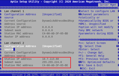
Go to “Server Mgmt.” tab → “BMC network configuration."
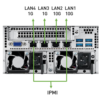
The “Station IP address” is the address of the IPMI controller. DHCP may need to be configured in order to provide a lease for the MAC address. The NVIDIA Skyway appliance has 2 LAN ports on the back panel of the appliance that can be used for IPMI (in the figure below IPMI LAN2 is used).
Use the following IPMI command to remotely access serial console (user and password should be “admin” by default).
ipmitool -I lanplus -H <IPMI_CONTROLLER_IP> -U <user> -P <password> sol activate
Example:
ipmitool -I lanplus -H
10.7.113.60-U admin -P admin sol activate
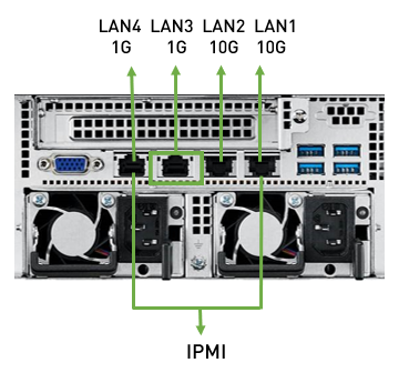
WarningMake sure to connect to the console SOL port of the gateway and not to the management port. Of the four ports, either of the outer ports (1st or 4th port—either to IPMI LAN1 or IPMI LAN 4, in the image above) can be selected to be the SOL port.
WarningOnce operating system boots, iKVM over HTML5 no longer shows any output. However, iKVM over HTML5 can be used for BIOS configurations at the very beginning of the system boot sequence right before the operating system boots.
Configure Console Redirection. This configuration allows to use remote IPMI to see all serial output that comes after the initial boot, useful for monitoring the OS init flow.
Go to “Advanced” tab → “Serial Port Console Redirection” → Under “Serial Communication via IPMI COM".
Set “Console Redirection” to “Enabled”.
ImportantAt this point, make sure to disconnect the VGA monitor and USB keyboard, or else the following error may appear:
TSC_DEADLINE disabled due to Errata; Please update microcode to version : 0xffffffff or later
Log in as admin and use admin as password, using IPMI.
ipmitool -I lanplus -H <IP Address> -U admin -P admin sol activate
Connect the management Ethernet cable to LAN3 (second port from the left) on the back panel of the appliance.
Go through the Gateway Management configuration wizard.
IP Configuration by DHCP
Wizard Session Display (Example)
Comments
Do you want to use the wizard for initial configuration? yes
This configuration must be performed the first time the gateway is operated or after resetting the gateway to the factory defaults.
Type “y” and then press <Enter>.Step 1: Hostname? [gateway-1]
To accept the default hostname, press <Enter>.
Otherwise, type a different hostname and press <Enter>.Step 2: Use DHCP on mgmt0 interface? [yes]
Perform this step to obtain an IP address for the gateway (mgmt0 is the management port of the gateway).
Typing “yes” will have the DHCP server assign the IP address
Typing “no” (no DHCP) will offer the use of the “zeroconf” configuration or not. For the use of Zeroconf, type "yes" and the session will continue. If “no” (no Zeroconf) is typed, enter a static IP and the session will continue.
Step 3: Enable IPv6 [yes]
Perform this step to enable IPv6 on management ports.
Type "yes" to enable enable IPv6.
Type “no” to not enable IPv6 (Step 4 will be skipped)
Step 4: Enable IPv6 autoconfig (SLAAC) on mgmt0 interface
Perform this step to enable StateLess address autoconfig on external management port.
Type "yes" to enable
Type "no" to disable
Step 5: Use DHCPv6 on mgmt0 interface? [yes]
Perform this step to enable DHCPv6 on the MGMT0 interface.
Step 6: Enable password hardening?
Perform this step to enable/disable password hardening on your machine. If enabled, new passwords will be checked upon configured restrictions. If you wish to enable it, type “yes” and press . If you wish to disable it, enter “no”
Step 7: Admin password (Must be typed)? <new_password>
To avoid illegal access to the machine, type a password and press <Enter>.
An admin password must be entered upon initial configuration. Due to California Senate Bill No. 327, this stage is required and cannot be skipped.
Step 8: Confirm admin password? <new_password>
Confirm the password by re-entering it. Note that password characters are not printed.
Step 9: Monitor password (Must be typed)? <new_password>
To avoid illegal access to the machine, please type a password and then press <Enter>.
An admin password must be entered upon initial configuration. Due to California Senate Bill No. 327, this stage is required and cannot be skipped.
Step 10: Confirm monitor password? <new_password>
Confirm the password by re-entering it. Note that password characters are not printed.
You have entered the following information:
Hostname: <gateway name>
Use DHCP on mgmt0 interface: yes
Enable IPv6: yes
Enable IPv6 autoconfig (SLAAC) on mgmt0 interface: yes
Enable DHCPv6 on mgmt0 interface: no
Enable password hardening: yes
Admin password (Enter to leave unchanged): (CHANGED)
To change an answer, enter the step number to return to.
Otherwise hit <enter> to save changes and exit.
Choice: <Enter>
Configuration changes saved.
To return to the wizard from the CLI, enter the “configuration jump-start” command
from configuration mode. Launching CLI...
<gateway name> [standalone: master] >
The wizard displays a summary of choices and then asks to confirm the choices or to re-edit them.
Press <Enter>, to save changes and exit
Enter the relevant configuration step number, to edit any of the choices
To run the command “configuration jump-start”, Config mode must be used.
Check the mgmt0 interface configuration before attempting a remote connection (e.g., SSH) to the gateway. Specifically, verify the existence of an IP address.
gateway # show interfaces mgmt0 Interface mgmt0 status: Comment : Admin up : yes Link up : yes DHCP running : yes IP address :
10.7.148.61Netmask :255.255.0.0IPv6 enabled : yes Autoconf enabled: no Autoconf route : yes Autoconf privacy: no DHCPv6 running : no IPv6 addresses :1IPv6 address: fe80::268a:7ff:fe53:3d8e/64Speed : 1000Mb/s (auto) Duplex : full (auto) Interface type : ethernet Interface source: physical MTU :1500HW address :00:02:c9:11:a1:b2 Rx:11700449bytes55753packets0mcast packets0discards0errors0overruns0frame Tx:5139846bytes28452packets0discards0errors0overruns0carrier0collisions1000queue len
Rerunning the Wizard
To rerun the wizard, do the following:
Enter config mode.
            gateway > enable
gateway # config terminal
Rerun the wizard.
gateway (config) # configuration jump-start
Starting the Command Line Interface (CLI)
Set up an Ethernet connection between the gateway and a local network machine using a standard SOL connector.
Start a remote secured shell (SSH) to the gateway using the command “ssh -l <username> <gateway ip address>”.
rem_mach1 > ssh -l <username> <ip address>
Log in to the gateway (default username and password are both "admin").
Read and accept the EULA, when prompted.
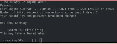
Once the following prompt appears, the system is ready to use.
-
            Mellanox Gateway

Password:
Last login: <time> from <ip-address>

gateway >
-
If firmware was upgraded, firmware boot bar will appear and the CLI will be blocked until firmware upgrade is complete.
The CLI will be blocked until InfiniBand virtual interfaces are created. The following message will appear : "Creating VFs".
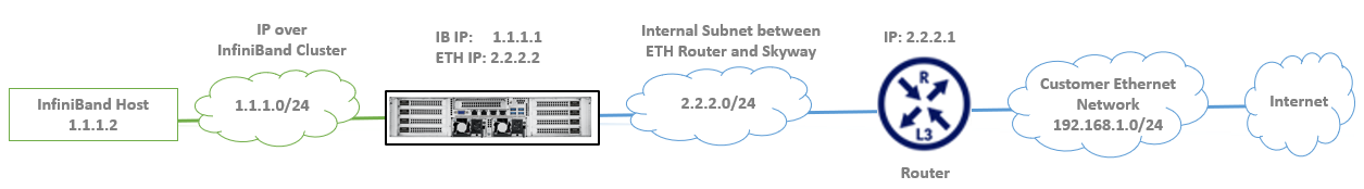
Skyway GA100 is an appliance-based InfiniBand-to-Ethernet gateway, enabling Ethernet-based communications to access the InfiniBand datacenter and vice versa. The following section describes networkwide guidelines and provides a specific example when using a NVIDIA Ethernet switch running NVIDIA Onyx™operating system.
Ensure the Subnet Manager is running in the InfiniBand cluster with IPoIB enabled.
The IPs and subnet masks described in the diagram below are provided as an example. Actual IP and subnet masks may differ in actual customer deployments.
General Networkwide Guidelines
Ethernet Guidelines
The connection between the Skyway and the Ethernet router requires configuring a LAG with active LACP on the Ethernet router (see step 3 in the "Configuring IP Addresses and Routes" below).
For increased resiliency, it is recommended to configure Ethernet routers in an MLAG configuration.
Make sure MTU on the Ethernet router connected to Skyway isat least 2 bytessmaller than the InfiniBand IPoIB MTU configuration (e.g. set InfiniBandMTU to 4092 and Ethernet MTU to 4090).
InfiniBand Guidelines
All InfiniBand ports must be connected to the same InfiniBand fabric.
Subnet Manager Configuration
Ensure the Subnet Manager is running in the InfiniBand cluster with IPoIB enabled.
Virtualization must be enabled by the Subnet Manager (SM). It is recommended to unlimit the maximum number of ports that are processed simultaneously.
If opensm runs on an InfiniBand switch, configure the following:
            switch (config) # ib sm virt enable
switch (config) # ib sm virt-max-ports-in-process 0
If opensm runs on a host, add the following lines to the opensm.conf (by default at /etc/opensm/opensm.conf):
            # Virtualization support
# 0: Ignore Virtualization - No virtualization support
# 1: Disable Virtualization - Disable virtualization on all
# Virtualization supporting ports
# 2: Enable Virtualization - Enable (virtualization on all
# Virtualization supporting ports
virt_enabled 2


# Maximum number of ports to be processed simultaneously
# by Virtualization Manager (0 - process all pending ports)
virt_max_ports_in_process 0
Configuring IP Addresses and Routes
The first port (port #1) of each HCA is an InfiniBand port and the second port (port #2) is an Ethernet port; therefore, the configuration of an InfiniBand "device/port" value should be "x/1" and the configuration of an Ethernet "device/port" value should be "x/2".
For example, for HCA #7, the configuration of the InfiniBand port is 7/1 and of the Ethernet port is 7/2.
IP addresses, subnet masks, port numbers, and interface names are used as an example and may vary according to the actual connectivity of the customer's deployment.
On the relevant InfiniBand nodes, configure an IP address on each InfiniBand port designated for the Skyway deployment (e.g., ib0). In addition, configure a default route with the Skyway IP as next hop (in this example, 1.1.1.3).
# ifconfig ib0
1.1.1.2/24# ip route add0/0via1.1.1.3WarningThe NVIDIA Skyway IP which is configured as next hop should match the virtual IP of the InfiniBand port channel of the NVIDIA Skyway appliance.
Access and configure an IP address on the gateway's Ethernet and InfiniBand ports and configure a virtual IP address on the InfiniBand port. In addition, configure a route to the customer's Ethernet networks via the IP assigned on the Ethernet router's port (in this example, 2.2.2.1).
gateway > enable gateway # configure terminal gateway (config) #
interfaceib port-channel1ip address1.1.1.1/24gateway (config) #interfaceib port-channel1virtual ip address1.1.1.3/24gateway (config) #interfaceethernet port-channel1ip address2.2.2.2/24gateway (config) # ip route0/02.2.2.1Detect the ports on the Ethernet router that are connected to the gateway, assign the LAG to a VLAN, and configure the IP address on the VLAN interface. In addition, configure a route to the IPoIB network via the IP assigned to the gateway's Ethernet port-channel (in this example, 2.2.2.2).
Below is an example using a NVIDIA-Onyx-based switch with port 1/1 connected to the gateway.
In this example, ports 1-8 on the router (see line 7) are connected to the 8 Ethernet ports on Skyway.eth_router > enable eth_router # configure terminal eth_router (config) # ip routing eth_router (config) # lacp eth_router (config) #
interfaceport-channel1eth_router (configinterfaceport-channel1) # exit eth_router (config) #interfaceethernet1/1-1/8channel-group1mode active eth_router (config) # vlan2eth_router (config vlan2) # exit eth_router (config) #interfaceport-channel1switchport access vlan2eth_router (config) #interfacevlan2ip address2.2.2.1/24eth_router (config) # ip route1.1.1.0/242.2.2.2WarningNote that the above connection describes a connection between Skyway and a single Ethernet router with LAG. It is possible to also connect to two Ethernet routers in an MLAG configuration. For more information, see the following community post for MLAG configuration on NVIDIA Onyx-based switches: support.mellanox.com/s/article/how-to-configure-mlag-on-mellanox-switches.
To ensure proper deployment, ping between a host in the subnet 192.168.1.0/24 and the InfiniBand host with IP 1.1.1.2 should be successful.
Deployment Scenarios
The gateway can be used in various deployment topologies, each with their particular strength.
Skyway Connectivity to the InfiniBand Using Fat Tree Topology
Option #1: 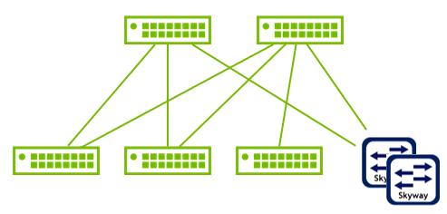
The Skyway appliances are connected to the Spine switches of the Fat Tree. This topology requires fewer hops to reach the Skyway, though, on the other hand, the Spine ports are occupied instead of keeping them available for future expansion of the cluster. |
Option #2: 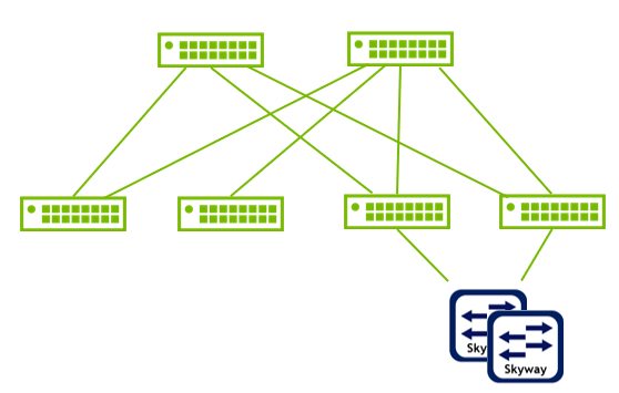
The Skyway appliances are connected to the Leaf switches. This topology makes Spine ports available for future expansion, though, on the other hand, the hop count from cluster nodes to the Skyway are not even—there may be nodes with a fewer hop count than others. |
Skyway Connectivity to the InfiniBand Using Dragonfly+ Topology
Option #1: 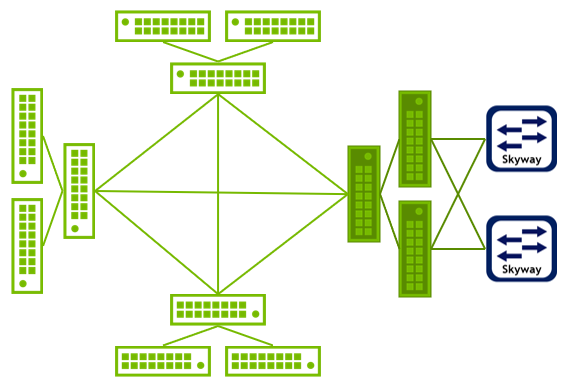
The Skyway appliances are connected to a dedicated cell for services (e.g., storage and login services). This topology provides fairness and symmetry among all nodes on all other cells, though, on the other hand, it requires having an additional cell (or "services island"). |
Option #2: 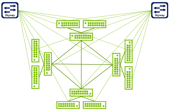
The Skyway appliances are connected directly to leaf switches on the compute islands. An additional cell (or "service island") is not required. |
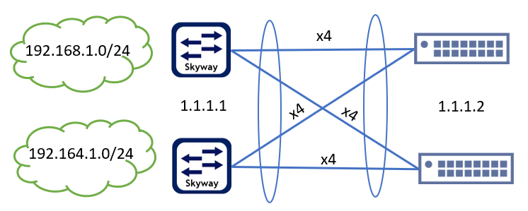
Skyway Connectivity to the Ethernet Using LAG/MLAG
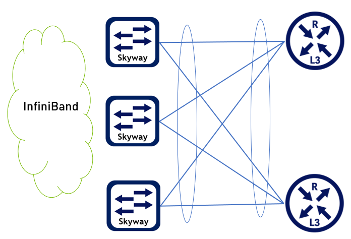
The clearest advantage of LAG/MLAG is that it is a simple and standard topology. While the topology provides a good load distribution and good resiliency, it is limited in scale. For more information on configuring MLAG, see the following community post. |
Please consider the following while implementing LAG/MLAG using Skyway appliances:
There is no Inter Peer Link (IPL) across Skyway appliances.
Skyway-based MLAG cannot be VLAN enabled. Ports are always access.
All Skyway appliances in an MLAG domain will share the same Virtual IP.
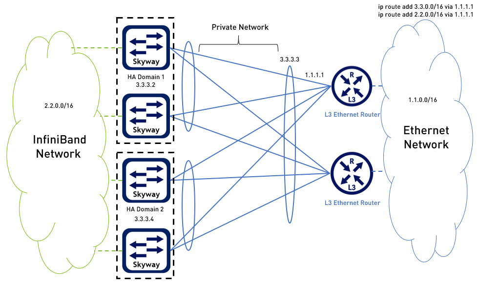
Multiple IP Subnets
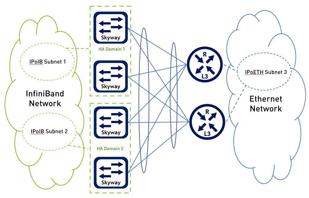
Multiple IP subnets can be configured over the InfiniBand network. In such cases, every IPoIB subnet will be served by dedicated Skyway appliances that are configured in High Availability (HA) Domain. The specific IP configuration (e.g., Default Gateway, Next Hop Router, and so forth) will have to be configured separately per HA domain of the Skyway appliances. Warning
|
Configuring High Availability (HA)
This section explains how to configure a HA cluster with multiple appliances.
Before Configuring HA
For all appliances in the HA cluster, the MLNX-GW version must the same.
For all appliances in the HA cluster, the Ethernet management interfaces must be in the same L2 subnet.
The Skyway appliances configured in HA mode must be connected to either Ethernet L3-dedicated switch or Ethernet L2 where all ports connected to Skyway are configured as router ports.
Before configuring HA, each appliance should be configured according to a the "Configuring IP Addresses and Routes" section above.
Virtual IP configuration and Ethernet port channel configuration must be identical for all appliances in the HA cluster.
Example of configuration that needs to be identical for all appliances:
Skyway A:gateway(config) #
interfaceib port-channel1virtual ip address1.1.1.3/24gateway(config) #interfaceethernet port-channel1ip address2.2.2.2/24Skyway B:
gateway(config) #
interfaceib port-channel1virtual ip address1.1.1.3/24gateway(config) #interfaceethernet port-channel1ip address2.2.2.2/24The ib port channel IP address may be different between the appliances in the HA cluster:
Skyway A:gateway(config) #
interfaceib port-channel1ip address1.1.1.1/24Skyway B:
gateway(config) #
interfaceib port-channel1ip address1.1.1.4/24Make sure that all Ethernet interfaces that are connected to Skyway appliances in the same HA cluster are connected through an Ethernet MLAG or LAG configuration.
Below is an example of MLAG and MAGP configuration on Ethernet switches connected to Skyway appliances.eth_router > enable eth_router # configure terminal eth_router (config) # protocol mlag eth_router (config) # lacp eth_router (config) # vlan
999eth_router (config vlan999) # exit eth_router (config) #interfacevlan999ip address192.17.10.3/24primary eth_router (config) #interfaceport-channel1eth_router (configinterfaceport-channel1) # exit eth_router (config) #interfaceethernet1/1-1/4channel-group1mode active eth_router (config) #interfaceport-channel1ipl1eth_router (config) #interfacevlan999ipl1peer-address192.17.10.2eth_router (config) # mlag-vip GW-HA ip10.10.252.10/16force eth_router (config) # no mlag shutdown eth_router (config) #interfacemlag-port-channel101eth_router (configinterfacemlag-port-channel101) # exit eth_router (config) #interfaceethernet1/19-1/26mlag-channel-group101mode active eth_router (config) #interfacemlag-port-channel101no shutdown eth_router (config) # ip routing eth_router (config) # vlan101eth_router (config vlan101) # exit eth_router (config) #interfacevlan101ip address2.2.2.252/24primary eth_router (config) #interfacemlag-port-channel101switchport access vlan101eth_router (config) # protocol magp eth_router (config) #interfacevlan101magp101eth_router (configinterfacevlan101magp101) # ip virtual-router address2.2.2.254eth_router (configinterfacevlan101magp101) # ip virtual-router mac-address AA:BB:CC:00:01:01eth_router (config) # ip route vrfdefault172.0.0.0/82.2.2.2Below is an example of LAG configuration on Ethernet switch connected to Skyway appliances. Ports 1–8 on the router are connected to the 8 Ethernet ports on the first Skyway appliance and ports 11-18 on the router are connected to the 8 Ethernet ports on the second Skyway appliance.
eth_router > enable eth_router # configure terminal eth_router (config) # ip routing eth_router (config) # lacp eth_router (config) #
interfaceport-channel1eth_router (configinterfaceport-channel1) # exit eth_router (config) #interfaceethernet1/1-1/8channel-group1mode active eth_router (config) #interfaceethernet1/11-1/18channel-group1mode active eth_router (config) # vlan2eth_router (config vlan2) # exit eth_router (config) #interfaceport-channel1switchport access vlan2eth_router (config) #interfacevlan2ip address2.2.2.1/24eth_router (config) # ip route1.1.1.0/242.2.2.2
Even if working on a single Skyway appliance system, it is recommended to configure the appliance to have High Availability configuration on the system. This will allow to easily scale the topology in the future without needing to change a single Skyway appliance configuration. See section "Configuring HA on Skyway Appliance" below for configuration details.
Configuring HA on Skyway Appliance
Configure HA on the gateway. Configure HA on each Skyway appliance that is going to be a part of the HA cluster.
All Skyway appliances must share the same HA domain.Skyway A:
gateway (config) # gw ha
1Warning! Configuration is about to be saved and the system will be reloaded. Type'YES'to confirm the HA domain id change: YESSkyway B:
gateway (config) # gw ha
1Warning! Configuration is about to be saved and the system will be reloaded. Type'YES'to confirm the HA domain id change: YESWarningAfter this step, the Skyway appliances will be rebooted.
Once all systems complete the initialization, verify that all Skyway appliances were added properly to the HA cluster by running "show gw ha" from one of the Skyway appliances.
Verify domain ID appears as configured and all Skyway appliances appear in the output of the command.gateway (config) # show gw ha Global HA state: GW domain ID :
3Active HA nodes:3Master name : skyway-7HA domain nodes information: Name : skyway-8GW Operational state: active System guid : b8ce:f603:0075:6eda Priority :100Name : skyway-64GW Operational state: active System guid : b8ce:f603:0068:7e8a Priority :100Name : skyway-7<--- (local node) GW Operational state: active System guid : b8ce:f603:0075:6efa Priority :100
High Availability LAG/MLAG Setup
|
Skyway Connectivity to the Ethernet Using L2 Ethernet Switches
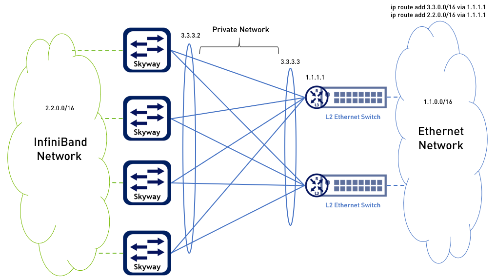
In this above use case, every Skyway-facing port on the side of the L2 Ethernet switches should be configured as a router port. In addition, a private network should be established (in the example above, 3.3.0.0/16) between the router ports mentioned above and the Skyways Ethernet port channel. |