BGP
Border Gateway Protocol (BGP) is an exterior gateway protocol which is designed to transfer routing information between routers. It maintains and propagates a table of routes which designates network reachability among autonomous systems (ASs).
BGP neighbors, or peers, are routers configured manually to converse using the BGP protocol on top of a TCP session on port 179. A BGP speaker periodically sends keep-alive messages to maintain the connection. Network reachability includes such information as forwarding destinations (IPv4 or IPv6) together with a list of ASs that this information traverses and other attributes, so it becomes possible to construct a graph of AS connectivity without routing loops. BGP makes possible to apply policy rules to enforce connectivity graph.
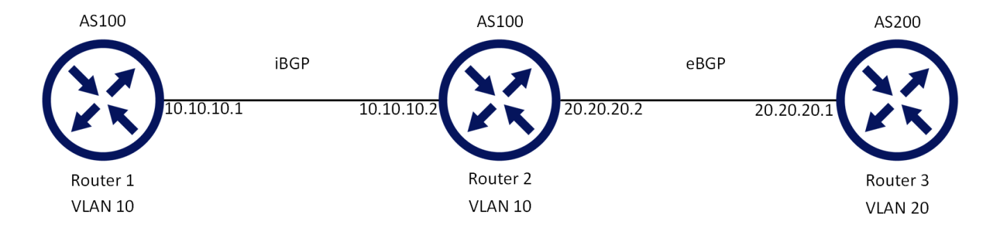
BGP routers communicate through TCP connection on port 179. Connection between BGP neighbors is configured manually or can be established dynamically by configuring dynamic listen groups. When BGP runs between two peers in the same AS, it is referred to as Internal BGP (iBGP, or Interior Border Gateway Protocol). When it runs between separate ASs, it is called External BGP (eBGP, or Exterior Border Gateway Protocol). Both sides can initiate a connection, after the initial connectivity is created, BGP state machine drives both sides to enter into ESTABLISHED state where they can exchange UPDATE messages with reachability information.
In order to make decisions in its operations with peers, a BGP peer uses a simple finite state machine (FSM) that consists of six states: Idle; Connect; Active; OpenSent; OpenConfirm; and Established. For each peer-to-peer session, a BGP implementation maintains a state variable that tracks which of these six states the session is in. The BGP protocol defines the messages that each peer should exchange in order to change the session from one state to another.
The first state is the “Idle” state. In “Idle” state, BGP initializes all resources, refuses all inbound BGP connection attempts and initiates a TCP connection to the peer. The second state is “Connect”. In the “Connect” state, the router awaits the TCP connection to complete and transitions to the “OpenSent” state if successful. If unsuccessful, it initializes the ConnectRetry timer and transitions to the “Active” state upon expiration. In the “Active” state, the router resets the ConnectRetry timer to zero and returns to the “Connect” state. In the “OpenSent” state, the router sends an Open message and waits for one in return in order to transition to the “OpenConfirm” state. KeepAlive messages are exchanged and, upon successful receipt, the router is placed into the “Established” state. In the “Established” state, the router can send/receive: KeepAlive; Update; and Notification messages to/from its peer.
Default Address Family defines which address family is activated when peer or peer-group becomes active.
When the default address family configuration is modified –it will cause a renegotiation of capabilities for all neighbors that do not have explicit configuration of active address families. The default address family in BGP is IPv4.
Default Route Originate initial value is set to “false”.
Any BGP peer can be defined as part of a peer group and it will inherit peer group configuration or have its own configuration.
A system will automatically generate an update group from peer groups members.
Peer that has a different outbound policy from peer-group will not become a part of update group.
Follow these steps for basic BGP configuration on two switches (Router 1 and Router 2):
Prerequisites:
Enable IP routing functionality. Run:
switch(config)# ip routingEnable the desired VLAN. Run:
switch(config)# vlan10WarningThe same VLAN must be configured on both switches.
Add this VLAN to the desired interface. Run:
switch(config)#interfaceethernet1/1switch(configinterfaceethernet1/1)# switchport access vlan10Create a VLAN interface. Run:
switch(config)#interfacevlan10Apply IP address to the VLAN interface on Router 1. Run:
switch(configinterfacevlan10)# ip address10.10.10.1/24Apply IP address to the VLAN interface on Router 2. Run:
switch(configinterfacevlan10)# ip address10.10.10.2/24Enable the interface. Run:
switch(configinterfacevlan10)# no shutdown
Configure BGP:
Enable BGP. Run:
switch(config)# protocol bgpConfigure an AS number that identifies the BGP router. Run:
switch(config)# router bgp100WarningTo run iBGP, the AS number of all remote neighbors should be identical to the local AS number of the configured router.
Configure BGP Router 1 neighbor. Run:
switch(config router bgp100)# neighbor10.10.10.2remote-as100Configure BGP Router 2 neighbor. Run:
switch(config router bgp100)# neighbor10.10.10.1remote-as100
Check the general status of BGP. Run:
switch(config)# show ip bgp summary BGP router identifier10.10.10.1, local AS number100BGP table version is100, main routing table version1000network entries using0bytes of memory0path entries using0bytes of memory0BGP AS-PATH entries using0bytes of memory0BGP community entries using0bytes of memory0BGP extended community entries using0bytes of memory Neighbor V AS MsgRcvd MsgSent TblVer InQ OutQ Up/Down State/PfxRcd10.10.10.201001007630000:0:10:19ESTABLISHEDswitch(config)# BGP summary informationforVRFdefault, address family IPv4• Verify that the state of each BGP neighbor reached to ESTABLISHED state.
• If the neighbor is disabled (shutdown). The state of the neighbor will be IDLE.
• BGP incoming and outgoing messages should be incremented.
• The AS number of each neighbor is the correct one.Check the status of the neighbors. Run:
switch(config)# show ip bgp neighbors BGP neighbor is10.10.10.2, remote AS100, external link BGP version0, remote router ID0.0.0.0BGP State = ESTABLISHED Last read0:00:00:00, last write0:00:00:00, hold time is180, keepalive interval is60seconds Configured hold time is180, keepalive interval is60seconds Minimum holdtime from neighbor is0secondsYou should be able to see running BGP counters and ESTABLISHED state per active neighbor.
Ethernet Virtual Private Network (EVPN) technology provides L2 and L3 VPN services by advertising Ethernet MAC addresses and IP routes over BGP address family. This technology supports multiple forwarding planes including VXLAN.
BGP Layer2-EVPN address family distributes EVPN “routes” between EVPN enabled nodes where some of them are Virtual Tunnel Endpoints (VTEPs) with VXLAN functionality and some of them are transit nodes that perform BGP reflection functionality.
The following route types are defined by RFC 7432:
MAC/IP advertisement route (route type 2) – advertises MAC and IP addresses of end-systems and their mapping to broadcast domains (VXLAN VNIs and EVPN EVIs). It is used for unicast forwarding, ARP suppression, and advertising default gateway in the EVPN network.
Inclusive multicast Ethernet tag route (route type 3) – advertises EVPN bridge domain (EVI) and originating router IP address. The EVPN network uses those addresses to instantiate forwarding plane for BUM (Broadcast, unknown Unicast, unknown Multicast) traffic.
IP prefix route (type 5) – advertises IP prefix, IP gateway, IP address, and HW encapsulation (VNI in the case of VXLAN). This route is used to establish IP prefix LPM routing in the EVPN nodes.
Other route types (type 1 and 4) are used in multi-homing environments only.
RFC 7432 defines BGP attributes that should be used together with Layer-2 EVPN address family routes:
PMSI tunnel attributes – used for inclusive multicast Ethernet tag route to define multicast type (head end replication) and data path (VNI)
MAC mobility extended community – used in MAC/IP routes to inform neighbors about MAC roaming events
Default gateway – used by MAC/IP route to establish default gateway routes
Route targets – used by all routes to import and export BGP Layer-2 VPN to forwarding and from plane
BGP unnumbered feature enables a user to establish a BGP session through a P2P Layer-3 link (port or port-channel) without specifying what the IP address of the remote neighbor is, nor what the neighbor’s ASN number is.
This Layer-3 link is capable of running IPv6, so the system will use IPv6 link-local addresses that are automatically generated by each IPv6 interface of the local and remote peer. These addresses will be used to establish the BGP TCP session. The ASN number is ignored during the BGP session establishment.
Once IPv6 BGP session is established, the system is able to exchange IPv4 NLRIs (prefixes) over IPv6 BGP session using IPv6 link-local neighbor address as a next hop. The system associates the IPv6 link local address with that neighbor so that the neighbor will be used as a next hop for the routes.
This feature is useful when provisioning a big data center fabric:
It does not require allocation of an IP subnet on each pair of connected switches
It simplifies the massive configuration and automation
Remote link-local neighbor address should be available in the local neighbor cache. This address can be populated in any way (ping, static configuration, etc.). It is recommended to use the IPv6 Router Advertisement capability of the router so that the address is populated and refreshed periodically.
Only one neighbor should be available. If more than one exists, one of them is randomly selected.
An ARP entry for 169.254.101.101 is automatically created on each interface on which BGP Unnumbered is configured.
            switch (config) # show ip arp
VRF Name default:
   Total number of entries: 3
------------------------------------------------------------------------------------
   Address              Type            Hardware Address          Interface
------------------------------------------------------------------------------------
. . .
  169.254.101.101      Static ETH      24:8A:07:7B:85:08         eth 1/17
. . .
BGP unnumbered uses 169.254.101.101 as the unnumbered nexthop. As such, while using BGP unnumbered, do not use this address in your topology in the following usages:
The interface's IPv4 addresses
The prefix or nexthop of static routes
The ARP neighbor address
IBGP is not supported for BGP unnumbered.
For a basic BGP unnumbered configuration, do the following:
Enable IP routing and IPv6 routing
ip routing vrf
defaultipv6 routing vrfdefaultConfigure a vrf loopback interface
interfaceloopback1interfaceloopback1ip address25.1.1.1/32primaryinterfacevrfdefaultip address alias loopback1Enable IP and IPv6 forwarding on interface
interfaceethernet1/2no switchport forceinterfaceethernet1/2ip enableinterfaceethernet1/2ipv6 enable nointerfaceethernet1/2ipv6 nd ra suppressConfigure BGP
protocol bgp router bgp
200vrfdefaultEnable BGP unnumbered interfaces
router bgp
200vrfdefaultneighborinterfaceethernet1/2Test if the session connected well.
switch(config) # show ip bgp neighborsinterfaceethernet1/2BGP neighbor: ethernet1/2(fe80::268a:7ff:fe7b:8508), remote AS:100, link: external: BGP version :4Configured hold time in seconds :180keepalive interval in seconds (configured) :60keepalive interval in seconds (established with peer):60Minimum holdtime from neighbor in seconds :180Peer group : Neighbor configuration: ------------------------------------------------------------------------ Configuration IPV4 Unicast IPV6 Unicast L2VPN EVPN ------------------------------------------------------------------------ Configured AFI SAFI Enabled Disabled Disabled Send Community Disabled Disabled Disabled Send Extended Community Disabled Disabled Disabled Route Reflection Disabled Disabled Disabled Next Hop Unchanged Disabled Disabled Disabled Extended next hop IPv4 Disabled Enabled Disabled Neighbor capabilities: Route Refresh : advertise and received Enhanced Route Refresh : advertise and received Soft Reconfiguration : Disabled Graceful Restart Capability: advertise and received Address family IPv4 Unicast: advertise and received Address family IPv6 Unicast: n/a Address family L2VPN EVPN : n/a Extended next hop IPv4 : advertise and received Message statistics: InQ depth :0OutQ depth:0...... Connection Information: Connections established :1Dropped :0Last Reset :0:00:00:36Last Drop Reason :0(0) Maximum hops to external BGP neighbor:1Connection State : ESTABLISHED Local host : fe80::268a:7ff:fe7b:8408Local port :43870Foreign host : ethernet1/2(fe80::268a:7ff:fe7b:8508) Remote port :179
For more information about this feature and its potential applications, please refer to the following community posts: