IP Routing Overview
NVIDIA Onyx supports the following 3 types of IP interfaces:
VLAN interface
Loopback interface
Router port interface
Onyx supports up to 999 IP interfaces.
Each IP interface can be configured with multiple IP addresses. The first address assigned to the interface automatically becomes its primary address (only one primary address is supported per interface), and the rest are secondary addresses.
Secondary addresses are advertised via OSPF. No “HELLO” messages are sent on them and no adjacencies are established on them either.
Primary addresses cannot be modified once assigned. To assign a different primary address, all addresses of the interface must be removed and then reconfigured.
Up to 16 IPv4 (as well as IPv6) addresses are supported on each IP interface.
IPv4 link local IP addresses such as 169.254.x.x can be assigned to IP interfaces, thus allowing all routing, forwarding functions and applications on top of the interfaces to function as the real IP addresses. Only unique addresses from that range can be assigned to IP interface, same address assignment is not supported.
Since 169.254.101.101 is already used as BGP unnumbered neighbor address, it is recommended not to use this address in the network if BGP unnumbered neighbor is to ever be enabled.
VLAN Interfaces
VLAN interface is a logical IPv4 interface created per subnet over a specific 802.1Q VLAN ID. If two hosts from two different subnets need to communicate (via the IP layer), the network administrator needs to configure two interface VLANs, one for each of the subnets.
Each interface VLAN has the following attributes:
Admin state
Operational state
MAC address
IP address and mask
MTU
Description
Set of counters
Loopback Interfaces
Loopback interface is a logical software entity where traffic transmitted to this interface is immediately received on the sending end.
Router Port Interfaces
Router port interface is a regular switch port configured to operate as an L3 interface. Router port interfaces are assigned an IP address and all L3 commands become applicable to them.
Once configured, router port interfaces no longer partake in the bridging activities of the switch and VLANs configured on them are separate from the pool allocated for the switch ports.
Configuring a VLAN Interface
Create a VLAN. Run:
switch(config)# vlan10switch(config vlan10)# exitAssign a physical interface to this VLAN. Run:
switch(config)#interfaceethernet1/1switch(configinterfaceethernet1/1)# switchport mode accessswitch(configinterfaceethernet1/1)# exitThere must be at least one interface in the operational state “UP”. Run:
switch(config)# showinterfaceethernet1/1status Port Operational state Speed Negotiation ---- ----------------- ----- ----------- Eth1/1Up40Gbps No-NegotiationCreate a VLAN interface that matches the VLAN. Run:
switch(config)#interfacevlan10switch(configinterfacevlan10)#Configure an IP address and a network mask to the interface. Run:
switch(configinterfacevlan10)# ip address10.10.10.10/24Verify VLAN interface configuration. Run:
switch(configinterfacevlan10) # show interfaces vlan10Vlan10: Admin state : Enabled Operational state: Down Autostate : Enabled Mac Address :24:8a:07:f3:04:c8 DHCP client : Disabled IPv4 address:10.10.10.10/24[primary] Broadcast address:10.10.10.255[primary] Arp responder: Disabled MTU :1500bytes Arp timeout :1500seconds Icmp redirect: Enabled Description : my-ip-interfaceVRF :defaultCounters : Disabled
Configuring a Loopback Interface
Create a loopback interface. Run:
switch(config)#interfaceloopback2switch(configinterfaceloopback2)#Configure an IP address on the loopback interface. Run:
switch(configinterfaceloopback2)# ip address20.20.20.20/32Verify loopback interface configuration. Run:
switch(configinterfaceloopback2)# show interfaces loopback2Loopback2: IPv4 address:20.20.20.20/32[primary] Broadcast address:20.20.20.20[primary] MTU :1500bytes Description: my-loopback VRF :default
Configuring a Router Port Interface
Enter an Ethernet interface’s configuration context. Run:
switch(config)#interfaceethernet1/10switch(configinterfaceethernet1/10)#Configure the Ethernet interface to become an router port interface. Run:
switch(configinterfaceethernet1/10)# no switchport forceConfigure an IP address on the router port interface. Run:
switch(configinterfaceethernet1/10)# ip address100.100.100.100/24Verify router port interface configuration. Run:
switch(configinterfaceethernet1/10)# show interfaces ethernet1/10Eth1/10: Admin state : Enabled Operational state : Down Last change in operational status: Never Boot delay time :0sec Description : N/A Mac address :24:8a:07:f3:04:c8 MTU :1500bytes (Maximum packet size1522bytes) Fec : auto Flow-control : receive off send off Supported speeds : 1G 10G 25G Advertised speeds : 1G 10G 25G Actual speed : Unknown Auto-negotiation : Enabled Width reduction mode : Unknown DHCP client : Disabled Autoconfig : Disabled IPv4 address:100.100.100.100/24[primary] Broadcast address:100.100.100.255[primary] Arp responder: Disabled Arp timeout :1500seconds VRF :defaultForwarding mode: inherited cut-through Telemetry sampling: Disabled TCs: N\A Telemetry threshold: Disabled TCs: N\A Telemetry threshold level: N\A Last clearing of"show interface"counters: Never60seconds ingress rate :0bits/sec,0bytes/sec,0packets/sec60seconds egress rate :0bits/sec,0bytes/sec,0packets/sec Rx:0packets0unicast packets0multicast packets0broadcast packets0bytes0discard packets0error packets0fcs errors0undersize packets0oversize packets0pause packets0unknown control opcode0symbol errors Tx:0packets0unicast packets0multicast packets0broadcast packets0bytes0discard packets0error packets0hoq discard packets
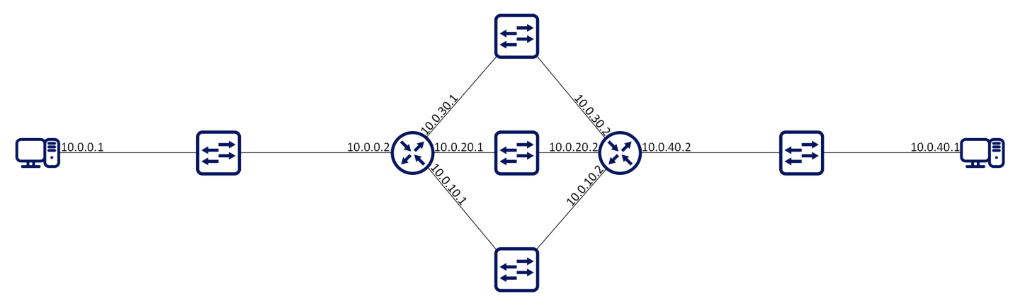
Equal-cost multi-path routing (ECMP) is a routing strategy where next-hop packet forwarding to a single destination can occur over multiple paths.
In the following figures, routers R1 and R2 can both access each of their router peer networks. Router R1 routing table for 10.0.40/24 will contain the following routes:
10.0.10.2
10.0.20.2
10.0.30.2
The load balancing function of the ECMP is configured globally on the system.
Hash algorithm can be symmetric or asymmetric. In symmetric hash functions bidirectional flows between routes will follow the same path, while in asymmetric hash functions, bidirectional traffic can follow different paths in both directions.
The following load balancing types are supported:
Source IP & Port – source IP (SIP) and source UDP/TCP port: If the packet is not UDP/TCP, only SIP is used for the hash calculation. This is an asymmetric hash function.
Destination IP & Port – destination IP (DIP) and destination UDP/TCP port: If the packet is not UDP/TCP, only DIP is used for the hash calculation. This is an asymmetric hash function.
Source and Destination IP & Port – destination and source IP, as well as destination and source UDP/TCP port: If the packet is not UDP/TCP, only SIP/DIP are used for the hash calculation. This is a symmetric hash function.
Traffic Class – Load balance based on the traffic class assigned to the packet. This is an asymmetric hash function.
All (default) – all above fields are part of the hash calculations. This is a symmetric hash function.
Hash Functions
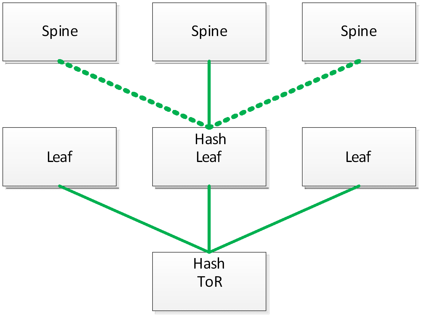
It is advised that LAG and ECMP hash function configuration over more than one hop is different. If the same hash function is used over two hops, all the traffic sorted from one hop to following one will arrive already having the same characteristics, which will render the next hash function useless. For example, configure load-balancing on the first hop based on source IP while on the next hop based on destination IP.
ECMP Consistent Hashing
In an IP network multiple flows share the same path defined by their destination prefix. ECMP allows those flows to travel with the same prefix and be distributed over multiple next hops that usually belong to different physical links, in order to reach better bandwidth utilization. When using the standard ECMP some links in the network become unreachable, thus the next hop list and hash function distribution change, and flows are moved to other links. Packet reordering in the network or failure in a user session might occur, while others which use anycast IP addresses utilize ECMP distribution for load balancing. Therefore, changing the next hop may cause flows to arrive to the wrong destination.
When network is reconfigured, and route next hop set is changed, flows that are not affected by the change should continue to be sent to the same next hops and keep the same outgoing link.
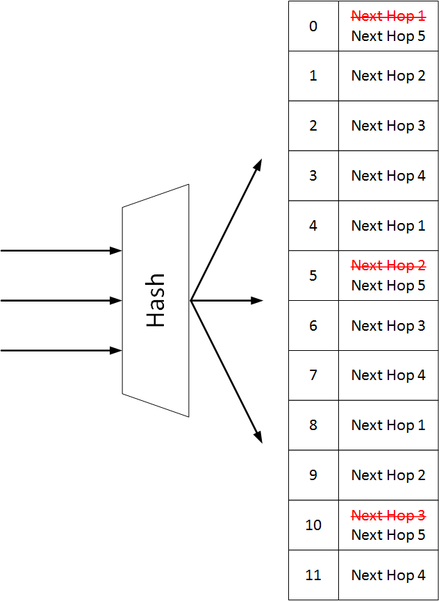
Using consistent hash containers enables you to use size arrays with next hop buckets to make sure unaffected flows are sent to the same next hops when some next hops are removed from the container. When a new next hop is added to the consistent hash container, some buckets are replaced with a new next hop, so part of the existing flows are moved to a new next hop.
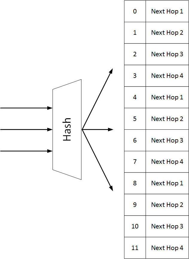
When a route is installed, it points to a hash container. Each flow in the route is mapped to a respective bucket, and is eventually forwarded to the next hop in the bucket.
In the following example we see a single route with 3 flows and 4 next hops, so the container has 12 bucket.
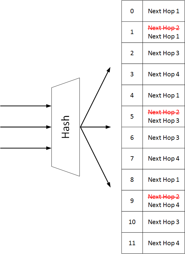
Remove Next Hops
Unlike the default IP load-sharing hashing, when consistent hashing is used, and a next hop needs to be removed, the number of hash buckets does not change. All appearances of the deleted next hop are removed from the container and replaced by the remaining next hops.
Add Next Hops
When adding a new next hop, some of existing next hops should be removed from the hash, and the new next hop should be located in one of the newly available places.The new next hops are not applied to HW immediately, but only after a convergence time period.
Supported Number of Containers
When the consistent hashing containers count exceeds the maximum number of containers, the operational state of consistent hashing function will become “unstable” and the containers with the same next hop sets will be merged to release more resources. Once more resources are available to deploy the containers, the operation state will become “stable”.
In the unstable case which may result from lack of consistent hashing resources, the new route will be installed as a non-consistent route, and a random next hop from its next hop set will be chosen as the actual next hop and installed in hardware. The route will only be partially programed in hardware.
Container Bucket Size | Default Number of Containers | Maximum Number of Containers |
512 | 40 | 96 |
1024 | 20 | 48 |
Configuring Consistent Hashing
To configure consistent hashing, run “ip load-sharing type consistent”.
Virtual Routing and Forwarding
Virtual Routing and Forwarding (VRF) allows multiple routing table instances to coexist within the same router simultaneously. Since the routing instances are independent, IP addresses on each routing table may overlap without conflicting with each other.
VRF can be used for the following purposes:
Ensure customer privacy and security
Separate between management and user data
Support customers with the same address space
Support VPN
Multiple routing instances defined in the router can have different purposes and can be configured in different manners:
Different IP interfaces can be attached to different VRFs (only one IP interface can be in a single VRF)
Routing in VRF can be enabled or disabled
Each VRF component can run its own routing protocol independently from other instances
Differently configured IPv4 and IPv6 services
The first VRF in the system is created automatically and it is called “default” VRF. It cannot be deleted or configured.
Onyx supports up to 64 VRFs, 8 instances of BGP, and 8 instances of OSPF.
ARP functionality in IP/Ethernet networks is needed to provide mapping from IP addresses to L2 MAC addresses. This request may be sent in multiple cases:
A station wants to initiate an IP session with another station on the same IP subnet and needs to obtain its L2 address
A station wants to update other stations that its MAC address has changed
A station wants to check that the MAC address of its peer did not change
The peer responds with unicast ARP response.
The following are two scenarios when ARP responder functionality is needed:
Network wants to avoid broadcast in the network or on some parts of the network, so broadcast ARP packets are not distributed in that part of the network
There is no L2 connectivity between some parts of the network, and even IP addressing scheme does not reflect it
ARP responder answers a broadcast ARP requests that arrive to the switch.
ARP responder is configured on an IP interface (with or without IP address) of any type (e.g. VLAN interface, router port, or LAG).
Only IP interfaces in UP admin state respond to ARP.
This functionality is provided for all ARP entries that are configured or provided on the interface: Static, dynamic, or per protocol.
There is no need to enable IP routing in the system to enable ARP responder functionality.
If a user has multiple VRFs the interface can be created in any VRF. If IP routing is disabled the interface is created in default VRF.
ARP responder can be enabled together with IP routing and given an interface which can be used in routing.
When IP routing on the interface is enabled, all entries that have been used by the responder become ARP entries for the router and vice versa.
A user must avoid using ARP responder in broadcast networks—the system itself does not block it.
Configuring ARP Responder
In order to initialize ARP responder:
Create IP interface. Run:
switch(config) #interfacevlan10switch(configinterfacevlan10) #Initialize ARP responder on the interface. Run:
switch(configinterfacevlan10) # ip arp responderCreate static ARP entries on VLAN. Run:
switch(configinterfacevlan10) # ip arp172.130.11.100:11:22:33:44:55Create ACL to drop broadcast, and assign it to all relevant L2 interface (VLAN’s members). Run:
switch(configinterfacevlan10) # mac access-listnewswitch(configinterfacevlan10) # mac access-listnewseq-number10deny any FF:FF:FF:FF:FF:FF mask FF:FF:FF:FF:FF:FFswitch(configinterfacevlan10) #interfaceethernet1/3-1/5mac port access-groupnew
Usually layer 3 forwarding is done based on destination IP: a router will extract packet destination IP from the packet header, match it to its routing table in Longest prefix match order, and forward it according the lookup result. In some cases, it is required that the routing decision will depend on different criteria such as source IP, source or destination port, packet type, and so forth.
PBR provides a way to implement such behavior. PBR is implemented as match/action table and influence the destination to which a packet should go based on various packet fields and not only based on the destination IP address.
PBR is applied to ingress packets after Ingress ACL and OpenFlow rules for packets that are eligible for routing.