Precision Time Protocol (PTP)
This feature is currently not supported in Spectrum-3 based switches.
Synchronizing network applications require their wall clock time to be aligned precisely with a reference time source (to the order of micro seconds or less). To achieve such accuracy, the application needs the support of networking HW (switch and adapter card), to provide the means to stamp time-sensitive packets. It also requires a time synchronization protocol which would make use of the HW time stamping to adjust its wall clock time to an accurate clock in the network.
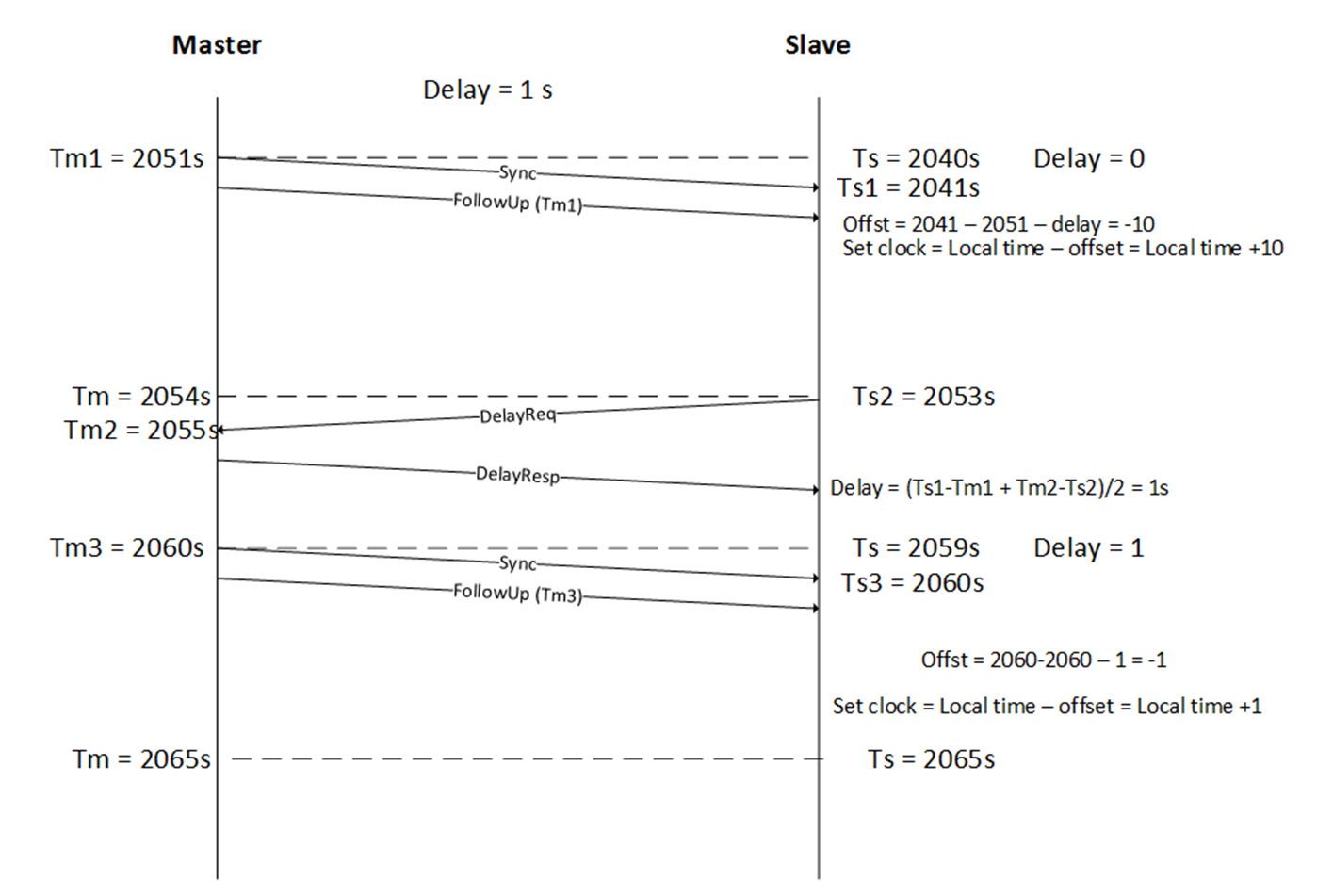
The basic principle of PTP is as follows: Slave time = master time + propagation delay + offset.
The purpose of the protocol is to align the slave and the master time so that the gap between them is the propagation delay of the packet. Or in other words, the purpose of the protocol is to use the offset to correct the slave time so the offset between the master sending the packet and the slave receiving the packet is the propagation delay.
Master time is sent periodically by a reliable clock source named Master Clock (MC). In a PTP network, one single reference source is elected called Grand Master Clock (GMC). Propagation delay is calculated between each node and the MC by one of the two methods provided by the standard and further explained below.
To reach sub-microsecond resolutions, all the time stamps which record when a packet is sent and received should be done in the HW. This may impose interaction between SW and HW to query the HW time and send follow-up messages. This issue is further explained below in 2 step section.
Assuming that the propagation delay in the network is symmetric, the propagation time is the average time that took the sync and delay req messages to be switched.
Propagation delay = (T4-T1-(T3-T2))/2=(T4-T1+T2-T3)/2
T1 represents the time that the packet left the master which is actually the master time.
The following figure provides an example of the stages required by a slave clock to align its time to the master clock:
The following table presents the PTP message formats:
Message Type | Hex Value | Class |
Sync | 0 | Event |
Follow-up | 8 | General |
Delay_Req | 1 | Event |
Delay_Resp | 9 | General |
Pdelay_Req | 2 | Event |
Pdelay_Resp | 3 | Event |
Pdelay_Resp follow-up | A | General |
Announce | B | General |
Signaling | C | General |
Management | D | General |
The types of clocks available are as follows:
Grand Master Clock (GMC)—the reference time source derived from an accurate clock such as a GNSS driven clock (i.e. GPS, GLONASS, GALILEO)
Boundary Clock (BC)—a network device that acts as slave to its master and as master to its slaves. (NVIDIA Onyx implements only this)
Ordinary Clock (OC)—a clock that operates either as a Master or a Slave. In the case of a slave, the end point whose clock is been synced (normally a host/server).
Master Clock (MC)—a clock which operates as a Master and derives its timing capabilities from the clock chain up to the GMC. It typically serves as a port on a BC connected to a host running as a slave.
Transparent Clock (TC)—a PTP aware switch capable of measuring the PTP packet switching delay (transient time) and updating the data in the packet. In peer-to-peer (P2P) delay calculation mechanism, a TC device is also required to calculate its delay from the next hop toward the MC and add the value to the switching delay.
Two modes of delay calculations are defined:
End-to-End (E2E)—each slave calculates its delay from the MC by running Delay request/ delay response sequence (NVIDIA Onyx implements only this)
Peer-to-Peer—propagation delay (Pdelay) is calculated periodically on each link between the slave and the MC independently. The time synchronization packet sent from the MC to all the slaves in the network is updated by each of the downstream nodes with both switching delay (the time that the packet traversed the switch) and upstream hop Pdelay.
A domain consists of one or more PTP devices communicating with each other. PTP domain defines the scope of PTP message communication, state, operations, data sets, and timescale.
Boundary Clock
In a full E2E PTP deployment, the GMC needs to respond to each slave’s delay request message. A normal profile of PTP may require a few delay calculations per second. An average GMC is capable of addressing few thousands of messages per second. This imposes that direct slave/GMC communication limits the number of overall OCs to ~8K. To scale beyond that, there is a need for a hierarchy between the GMC and the slave. This is achieved by implementing BC, either in the TOR switches or on all the switches in the DC.
The following figure shows the master/slave role that a boundary clock implements between the MC and the Slave (OC).
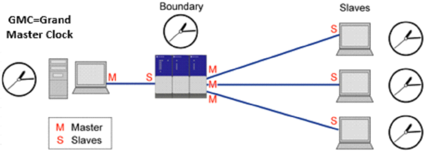
Each BC acts as a slave towards the GMC and as GMC to its local slaves. Although adding a BC device introduces accuracy degradation as explained above, it becomes mandatory when the number of slaves on a single MC exceeds few thousand devices.
Another use of BC is to bridge between networks. When running PTP over native Ethernet packets, to create larger PTP domains, there is a need to bridge between the broadcast domains. This is done by BC switches.
Default PTP Profile Attributes (SMPTE 2059-2)
Name | Range | Default |
Announce interval | -3 (0.125s), 1 (2s) | -2 (0.25s) |
Announce timeout interval | 2, 10 | 3 |
Sync interval (logSyncInt) | -7, -1 | -3 |
Delay request interval | logSyncInt, logSyncInt +5 | logSyncInt |
PTP domain | 0, 127 | 127 |
Priority 1 | 0, 255 | 128 |
Priority 2 | 0, 255 | 128 |
Configuring PTP
IEEE 1588 Precision Time Protocol (PTP) may be configured either on router or switch interfaces.
To enable PTP on a router interface you could simply enable it on the selected interface.
The process of configuring PTP on a switch interface is slightly different, however. PTP should be enabled on the interface itself as well as on the respective VLAN interface(s).
All PTP configuration for switch interfaces is taken from those defined on the VLAN interface.
Prior to enabling PTP, NTP must be disabled.
When changing PTP configurations, PTP process restarts.
PTP restarts under the following conditions:
Removing/adding PTP-enabled VLAN from switchport configuration.
Removing/adding physical interface to PTP-enabled list.
Any direct PTP configuration change (forced-master, AMT, intervals, and so forth).
To configure PTP on a router interface:
Enable the PTP CLI commands. Run:
switch(config) # protocol ptpConfigure the router interface. Run:
switch(config) #interfaceethernet1/1no switchport forceAdd the primary IP address. Run:
switch(config) #interfaceethernet1/1ip address172.16.1.1/24Enable PTP on the interface. Run:
switch(config) #interfaceethernet1/1ptp enable
To verify the PTP configuration:
            switch (config) # show ptp
PTP mode                : Boundary Clock
Message format          : Mixed
Acceptable Master Table : Enabled
Domain                  : 127
Clock identity          : 7c:fe:90:ff:fe:fa:21:88
GMC identity            : 7c:fe:90:ff:fe:fa:21:88
Number of master ports  : 1
Slave port interface    : N/A

PTP enabled interfaces:
  ----------------------------------------------------
  Port           VLAN      State        Forced Master
  ----------------------------------------------------
  Eth1/1         N/A       MASTER       no
To configure PTP on a switch interface:
Enable the PTP CLI commands. Run:
switch(config) # protocol ptpAdd the VLANs. Run:
switch(config) # vlan2-3Configure VLAN membership.
For access interfaces, run:switch(config) #interfaceethernet1/2switchport mode accessswitch(config) #interfaceethernet1/2switchport access vlan2For trunked interfaces, run:
switch(config) #interfaceethernet1/1switchport mode trunkEnable PTP on the VLAN interface. Run:
switch(config) #interfacevlan2ptp enableswitch(config) #interfacevlan3ptp enableEnable PTP on the interface. Run:
switch(config) #interfaceethernet1/1ptp enableWarningThe interface must be a member of the PTP enabled VLAN(s).
To verify the PTP configuration:
            switch (config) # show ptp
PTP mode                : Boundary Clock
Message format          : Mixed
Acceptable Master Table : Enabled
Domain                  : 127
Clock identity          : 7c:fe:90:ff:fe:fa:21:88
GMC identity            : 7c:fe:90:ff:fe:fa:21:88
Number of master ports  : 2
Slave port interface    : N/A

PTP enabled interfaces:
  ----------------------------------------------------
  Port           VLAN      State        Forced Master
  ----------------------------------------------------
  Eth1/1         2         MASTER       no
  Eth1/2         2         MASTER       no
  Eth1/1         3         SLAVE        no
To protect the switch from rogue or mis-configured PTP endpoints, you may secure your Boundary Clock ports by creating an Acceptable Master Table (AMT) and configuring known PTP ports to always behave as a master port via the Forced Master option.
The AMT is a whitelist of up to 8 clock identities that are admissible to take part as valid GrandMasters in the Best Master Clock Algorithm (BMCA).
The Forced Master is enabled on a per-port basis to prevent processing announce messages from a PTP endpoint connected to it, in order for it to always stay in a Master state.
To configure Forced Master on a switch interface, you must enable it on the interface itself as well as on the respective VLAN interface(s).
To configure Acceptable Master Table, add the validated clock identities:
            switch (config) # ptp amt E4:1D:2D:FF:FE:46:13:88
switch (config) # ptp amt E4:1D:2D:FF:FE:44:23:B7
To verify the Acceptable Master Table configuration:
            switch (config) # show ptp amt

Clock Identities:
  E4:1D:2D:FF:FE:44:23:B7
  E4:1D:2D:FF:FE:46:13:88
To enable Forced Master on a router interface:
switch (config) # interface ethernet 1/2 ptp enable forced-master
To verify PTP configuration:
            switch (config) # show ptp
PTP mode                : Boundary Clock
Message format          : Mixed
Acceptable Master Table : Enabled
Domain                  : 127
Clock identity          : 7c:fe:90:ff:fe:fa:21:88
GMC identity            : 7c:fe:90:ff:fe:fa:21:88
Number of master ports  : 1
Slave port interface    : N/A

PTP enabled interfaces:
  ----------------------------------------------------
  Port           VLAN      State        Forced Master
  ----------------------------------------------------
  Eth1/2         N/A       MASTER       yes
To configure Forced Master on a switch interface:
Enable Forced Master on the VLAN interface. Run:
switch(config) #interfacevlan2ptp enable forced-masterEnable Forced Master on the interface. Run:
switch(config) #interfaceethernet1/1ptp enable forced-masterWarningThe interface should be a member in the PTP enabled VLAN(s).
To verify PTP configuration:
            switch (config) # show ptp
PTP mode                : Boundary Clock
Message format          : Mixed
Acceptable Master Table : Enabled
Domain                  : 127
Clock identity          : 7c:fe:90:ff:fe:fa:21:88
GMC identity            : 7c:fe:90:ff:fe:fa:21:88
Number of master ports  : 2
Slave port interface    : N/A

PTP enabled interfaces:
  ----------------------------------------------------
  Port           VLAN      State        Forced Master
  ----------------------------------------------------
  Eth1/1         2         MASTER       yes
  Eth1/1         3         SLAVE        no
Forced Master is indicated as “yes” only if enabled on the interface and the corresponding VLAN interface.
For more information about this feature and its potential applications, please refer to the following:
IEEE 1588 Precision Time Protocol Design Guide → Guides (scroll to the bottom of the page)