Quality of Service (QoS)
QoS classification assigns a QoS class to the packet. The QoS class of the packet is indicated internally in the switch using the switch-priority parameter (8 possible values).
Switch-priority affects the packet buffering and transmission scheduling. There are 8 possible values for switch-priority. The classification is based on the PCP and DEI fields in the VLAN tag, the DSCP field in the IP header. In addition, the default value can be configured for the incoming port. And the switch-priority of the packet also can be reconfigured by the ACL.
The switch-priority of the packet is used for priority fields re-marking at the egress.
Trust Levels
QoS classification depends on the port configuration for QoS trust level which determines which packet header fields derive the switch-priority. The following trust states are supported:
Trust port
Based on port default settings
Trust L2 (PCP,DEI)
Based on packet PCP,DEI fields for VLAN tagged packets
Else, based on the port default setting for VLAN un-tagged packets
Trust L3 (DSCP)
Based on packet DSCP field for IP packets
Else, based on port default setting for non-IP
Trust both
Based on packet DSCP for IP packets
Else, based on packet PCP,DEI for VLAN tagged packets
Else, based on the port default setting
The following table and figure summarize the packet classification rules.
Packet Type | QoS Classification Config (per Interface) | ||||
IP/MPLS | VLAN | Trust Both | Trust L3 | Trust L2 | Trust Port |
IP/MPLS | Tagged | DSCP | DSCP | PCP,DEI | Port Default |
IP/MPLS | Untagged | DSCP | DSCP | Port Default | Port Default |
non-IP/MPLS | Tagged | PCP,DEI | Port Default | PCP,DEI | Port Default |
non-IP/MPLS | Untagged | Port Default | Port Default | Port Default | Port Default |
Default switch-priority is configured as trust L2.
Switch Priority to IEEE Priority Mapping
IEEE defines priority value for a packet which is used in the switch for the pause flow control.
The device maps the switch-priority into IEEE priority value using device global switch priority to IEEE priority table.
Default QoS Configuration
Parameter | Range | Configuration |
Trust level | All ports | Trust L2 |
DSCP to switch-priority | 0-7 | 0 |
DSCP to switch-priority | 8-15 | 1 |
DSCP to switch-priority | 16-23 | 2 |
DSCP to switch-priority | 24-31 | 3 |
DSCP to switch-priority | 32-39 | 4 |
DSCP to switch-priority | 40-47 | 5 |
DSCP to switch-priority | 48-55 | 6 |
DSCP to switch-priority | 56-63 | 7 |
PCP to switch-priority | 0 | 0 |
PCP to switch-priority | 1 | 1 |
PCP to switch-priority | 2 | 2 |
PCP to switch-priority | 3 | 3 |
PCP to switch-priority | 4 | 4 |
PCP to switch-priority | 5 | 5 |
PCP to switch-priority | 6 | 6 |
PCP to switch-priority | 7 | 7 |
Port PCP,DEI default | All ports | 0 |
Port switch-priority when “trust port” is enabled | All ports | 0 |
Switch-priority to IEEE priority | 0 | 0 |
Switch-priority to IEEE priority | 1 | 1 |
Switch-priority to IEEE priority | 2 | 2 |
Switch-priority to IEEE priority | 3 | 3 |
Switch-priority to IEEE priority | 4 | 4 |
Switch-priority to IEEE priority | 5 | 5 |
Switch-priority to IEEE priority | 6 | 6 |
Switch-priority to IEEE priority | 7 | 7 |
Control Protocols
Protocol | Switch Priority |
xSTP | Switch Priority 7 |
LACP | Switch Priority 7 |
LLDP | Switch Priority 7 |
PTP | Interface VLAN: Switch Priority 7 |
Router Port: Switch Priority 6 | |
BGP | Switch Priority 6 |
OSPF | Switch Priority 6 |
PIM | Switch Priority 6 |
IGMP | Switch Priority 6 |
MLAG | Switch Priority 6 |
SFLOW | Switch Priority 6 |
VRRP | Switch Priority 6 |
NVIDIA Spectrum enables rewriting QoS identifier values (DSCP, PCP, DEI) of incoming packets.
The configuration for preserving the values or rewriting them is set per ingress port. The configuration of the new values is set per egress port and is based on the mapping from the switch-priority.
In addition, the packets that pass the router module in the switch can be configured to change the “rewrite enable” configuration as well as the switch-priority.
Switch-priority to PCP,DEI Re-marking Mapping
Packet PCP and DEI fields can be updated by the switch based on switch-priority to PCP,DEI mapping tables. The mapping can be configured per egress port.
The reason for the mapping is to enable changing interpretation between two administrative domains in the network, or when a source of data is not fully trusted, and the default values are not desired. This mapping takes effect after deriving switch-priority from the PCP,DEI fields.
Switch-priority to DSCP Re-marking Mapping
Packet DSCP field can be updated based on switch-priority to DSCP mapping tables. The mapping can be configured per egress port. MPLS packets are untouched regardless this setting.
The reason for the mapping is to enable changing interpretation between two administrative domains in the network, or when a source of data is not fully trusted. This mapping will take effect after deriving switch-priority from the DSCP field.
DSCP to Switch-priority in Router
Spectrum enables mapping of DSCP to switch-priority in the router using a global mapping table. This mapping has global configuration for whether to change the “Rewrite/Preserve PCP,DEI” bit. This configuration sets how the DSCP to switch-priority would affect the packet.
Default Configuration
By default no ingress rewrite configuration is set
By default PCP rewrite configuration in router is set
The default mapping is as following:
Switch-priority=i to PCP,DEI=i,0, i=0-7
Switch-priority=i to DSCP=8i, i=0-7
Enhanced Transmission Selection (ETC) provides a common management framework for assignment of bandwidth to traffic classes, for weighted round robin (WRR) scheduling. If a traffic class does not use all the bandwidth allocated to it, other traffic classes can use the available bandwidth. This allows optimal utilization of the network capacity while prioritizing and providing the necessary resources.
The ETS feature has the following attributes:
ETS global admin
Enable (default)—scheduling mode is WRR according to the configured bandwidth-per-traffic class
Disable–scheduling mode is Strict Priority (SP)
Bandwidth percentage for each traffic class: by default each traffic class gets an equal share
After the output port of the packet is determined and the packet is buffered, it is queued for transmission. Each egress port is combined from the multi-level queuing structure. The scheduling of transmission from the queues relies on various configurations such as ETS weight, flow control, rate shaping etc.
Traffic Class
The switch-priority of the packet assigns it to a specific traffic class (TClass). The TClass of the packet determines the packet path in the queuing structure. There are 8 TCs supported by the system.
Traffic Shapers
Maximum Shapers
TCs can be configured for rate shaping as described in the following:
TClass queues: shaper per TClass queue
Port: shaper per port (bytes only)
Shapers support the following configurations:
Committed Incoming Rate (CIR) [bits/packets per second]
Committed Burst Size (CBS) [bits/packets]
Each shaper has granularity rate of 1Mb/s, 10Mb/s, 100Mb/s and 1Gb/s (or 128K, 1280K, 12M, 128M pps). The maximum CBS is 3GB or 384M packets.
Minimum Shapers
TC queues can be configured for minimal rate shaping. The minimum shaper configuration overrides all other scheduling configurations. So that if ETS or WRR scheduling allocates to a TC queue lower rate than the configured minimum, that queue receives strictly higher priority over the others. If several queues receive a rate below the configured minimum, the arbitration between them can be configured as a WRR, or as strict according to the queue index.
The configuration of min shaper is identical to the configuration of max shaper.
Default Shaper Configuration
Parameter | Range | Configuration |
Switch-priority to TC | 0 | 0 |
Switch-priority to TC | 1 | 1 |
Switch-priority to TC | 2 | 2 |
Switch-priority to TC | 3 | 3 |
Switch-priority to TC | 4 | 4 |
Switch-priority to TC | 5 | 5 |
Switch-priority to TC | 6 | 6 |
Switch-priority to TC | 7 | 7 |
Shaping | All ports | No max/min shaping configured |
Random early detection (RED) is a mechanism that randomly drops packets before the switch buffer fills up in case of congestion. Explicit congestion notification (ECN) is used for congestion control protocols (TCP and RoCE CC – DCQCN) to handle congestion before packets are dropped. RED and ECN can be configured separately or concurrently per traffic class.
Relative RED/ECN is supported on TC queues. This allows the thresholds of the drop/mark actions to behave relatively to the dynamic thresholds configured for the shared buffer.
RED/ECN drop profiles are defined according to 2 parameters as shown in the following figure:
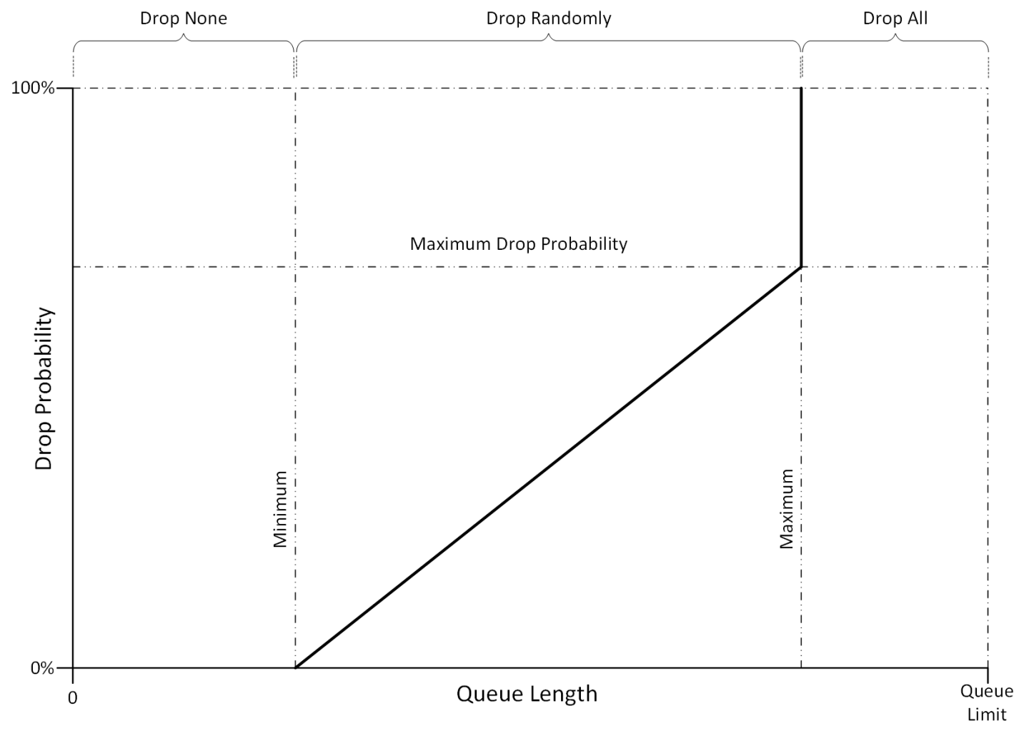
Minimum – a threshold that defines the average queue length below which the packets are not dropped/marked
Maximum – a threshold that defines the average queue length above which the packets are always dropped/marked
It is possible to configure the minimum and maximum thresholds to have the same value which would represent a step function from “drop none” to “drop all”.
RED/ECN is only supported for unicast traffic classes.
For more information about this feature and its potential applications, please refer to the following community posts: