SN2000 Dismantling Instructions
To dismantle the system, perform the following steps, while viewing the matching illustrations in the Component Illustrations table. To view the amounts of each component in your system, refer to the Component List below with the item number in the brackets. Once you are done dismantling all switch components, make sure you have all Screws, Nuts and Washers.
Cut all plastic cable ties (#15).
Remove all fan modules (#3) and power supply units (#4) by grasping their handles with your hand and pushing the latch release with your thumb while pulling the handle outward.
Unscrew all screws securing the chassis top cover, and remove it.
If there are cable clamps (#16), remove all of them.
Disconnect the following cables and harnesses from both sides, and remove them:
DC 2x3 F-F cable (#19)
Mini-SAS cable (#21)
Flex PCB (#12)
Unscrew and remove the I-O module (#11) assembly.
Remove all switch board cover stoppers (#17).
Remove the management board cover stoppers (#18).
Snap the pull-tab (#24) out of its slot in the front panel.
Unscrew all screws securing the connector panel (#1) to the chassis, and remove it.
Remove all air-buffers (#23).
Unscrew all screws securing the switch board (#7) to the chassis, and remove it, as well as all switch board spacers (#13).
Remove all PSU extenders (#8) and extender spacers (#14).
Unscrew all screws securing the management board (#6) to the chassis, and remove it.
To dismantle the system, perform the following steps, while viewing the matching illustrations in the Component Illustrations table. To view the amounts of each component in your system, refer to the Component List below with the item number in the brackets:
Unscrew all screws securing the chassis top cover, and remove it.
Snap the pull-tab (#24) out of its slot in the front panel.
Cut all plastic cable ties (#15).
Disconnect the fan harnesses from the main board, and remove the fan assembly (#3).
Disconnect the following cables and harnesses from both sides, and remove them:
Power harnesses (#5) from the power supplies to the switch board.
Signal harnesses (#10) from the power supplies to the switch board.
Remove the two AC inlets from their designated places
Unscrew all screws securing the power supplies (#4), and remove them.
Unscrew all screws securing the management board (#6) to the chassis, and remove it.
Unscrew all screws securing the switch board (#7) to the chassis, and remove it.
In SN2010 systems only:
Remove the LED divider and the LED board PCB (#2) by unscrewing all screws attaching it to the chassis.
Detach the Lexan label (#22) from the front panel by peeling the plastic strip.
Components
# | Component | SN2700M | SN2410M | SN2100M | SN2010M |
1. | Connector panel assembly | 1 | 1 | 1 | 1 |
2. | LED board PCB | - | - | 1 | - |
3. | Fan modules/drawers | 4 | 4 | 1 | 1 |
4. | Power supply units | 2 | 2 | 2 | 2 |
5. | Power supply to switch board harness | - | - | 1 left 1 right | 2 long 2 short |
6. | Management board/X86 board | 1 | 1 | 1 | 1 |
7. | Switch board | 1 | 1 | 1 | 1 |
8. | Power supply unit extenders | 2 | 2 | - | - |
9. | AC inlet to power supply harness | - | - | 2 | 2 |
10. | Signal harness from switch board to power supply | - | - | 2 | 2 |
11. | I-O module | 1 | 1 | - | - |
12. | SE flex PCB | 1 | 1 | - | - |
13. | Switch board spacers | 12 | 10 | - | - |
14. | PSU extender spacers | 2 | 2 | - | - |
15. | Cable ties | 6 | 1 | 9 | 9 |
16. | Cable clamps | 2 | - | - | - |
17. | Switch board cover stoppers | 3 | 4 | - | - |
18. | Management board cover stoppers | 1 | 1 | - | - |
19. | DC cable between management board and switch board | 1 | 1 | - | - |
20. | LED divider | - | - | 1 | - |
21. | Mini-SAS cable | 1 | 1 | - | - |
22. | Front Lexan label | 4 | - | - | - |
23. | Air buffers | 4 | - | - | - |
24. | Pull-tab | 1 | 1 | 1 | 1 |
# | Component | SN2700 | SN2410 | SN2100 | SN2010 |
a. | Pan head 4-40x5/16" double washer Phillips sems screw | 13 | 15 | - | - |
b. | Pan head 4-40x3/8" double washer Phillips sems screw | 13 | 6 | 7 | |
c. | Flat head 100º 4-40x3/16" Phillips patch screw | 35 | 27 | 16 | 17 |
d. | Flat head 100º 4-40x5/32" Phillips patch screw | 2 | - | - | - |
e. | Flat head 100º 2-56 x 1/8 Phillips patch screw 1 | - | 1 | - | - |
f. | Pan head 2-56x1/4" double washer Philips sems screw | - | - | 2 | - |
g. | Hexagon #8-32 nut | - | - | 2 | 2 |
h. | Serrated lock washer (DIN 6798 A) | - | - | 4 | 4 |
i. | Pan head m3x8 Phillips machine screw (DIN 7985-H) | - | - | 7 | |
j. | Pan head m3x6 Phillips double washer sems screw | - | - | 8 | 4 |
k. | Pan head m3x5 Phillips double washer sems screw | - | - | 4 | - |
l. | Pan head m3x8 Phillips double washer sems screw | - | - | - | 12 |
m. | Pan head 6-32 unc 1/4" Phillips double washer sems screw | - | - | - | 4 |
Note: The images in the following table are provided for illustration purposes only. The components may slightly vary, depending on the system's family and specific model.
# | Component | # | |
1. | Connector panel assembly: 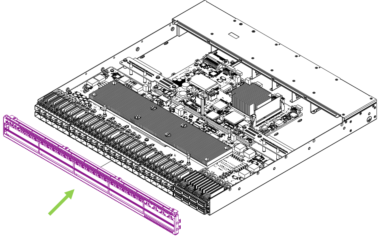
| 2. | LED board PCB: 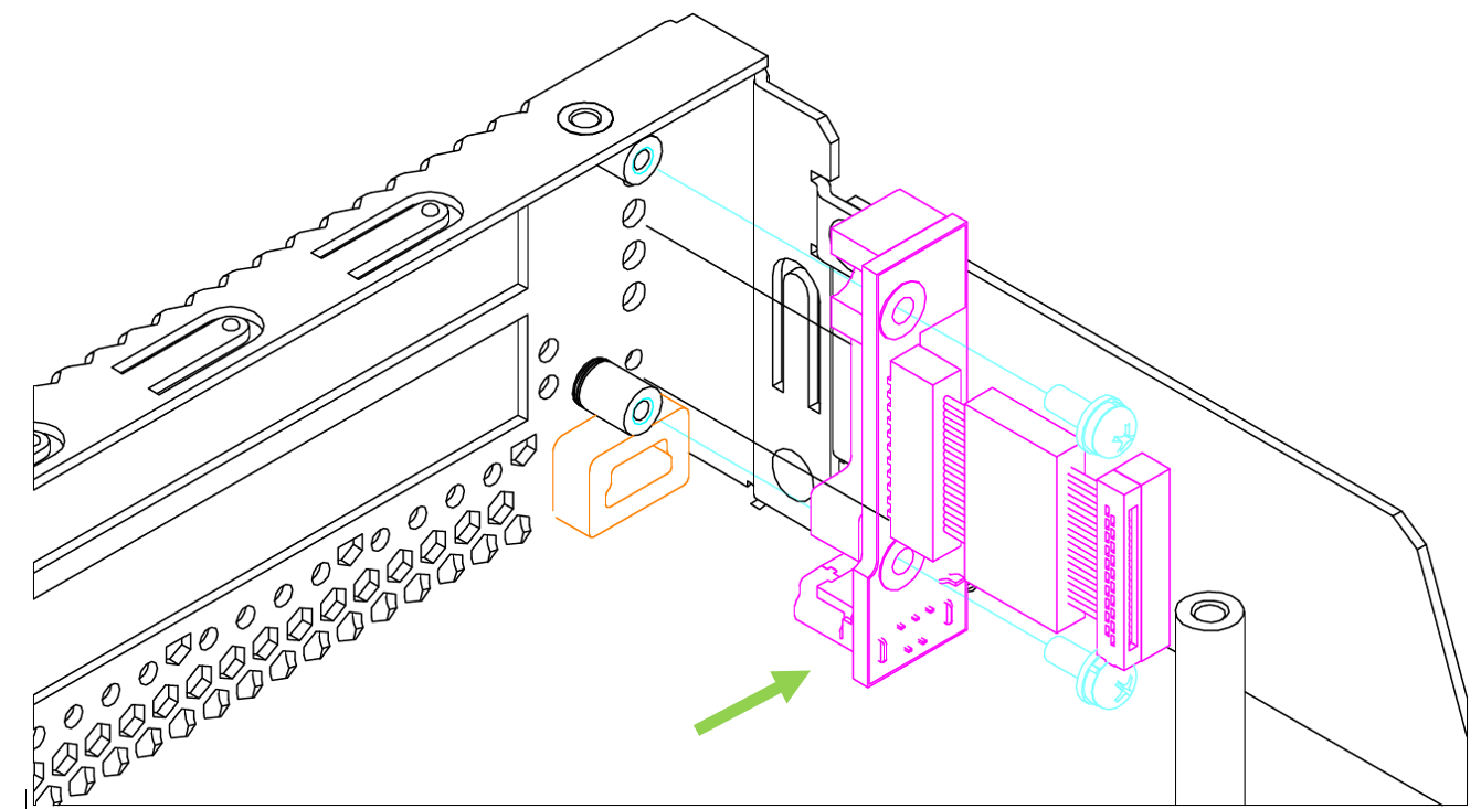
|
3. | Fan modules/drawers: 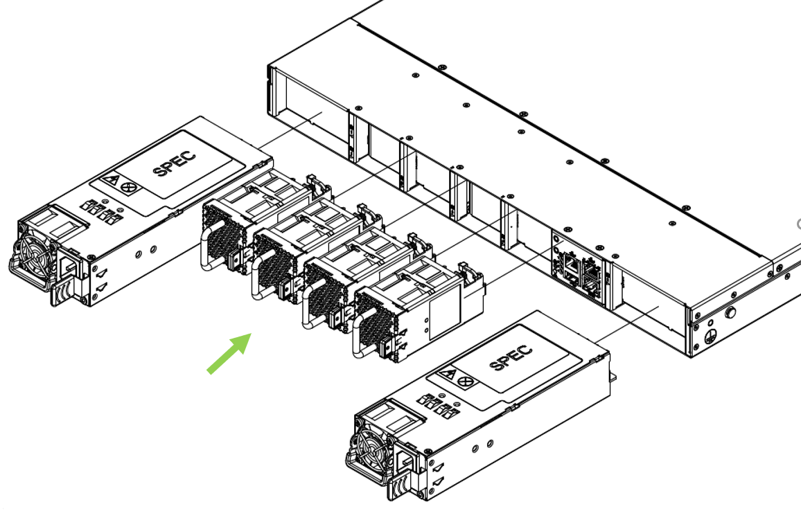
Fan assembly: 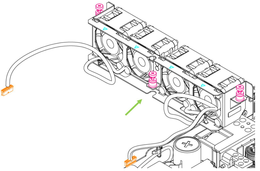
| 4. | Power supply units: 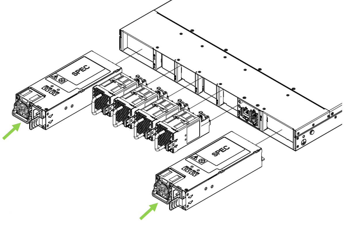
Power supply (internal): 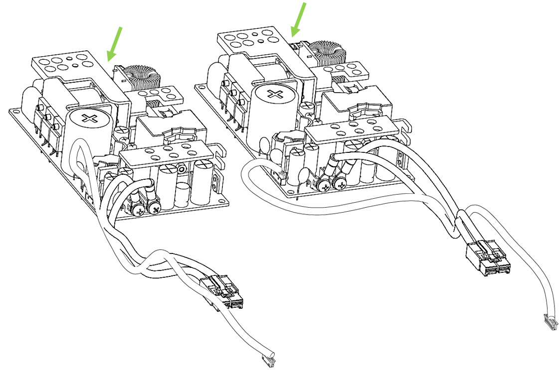
|
5. | Power supply to main board harness: 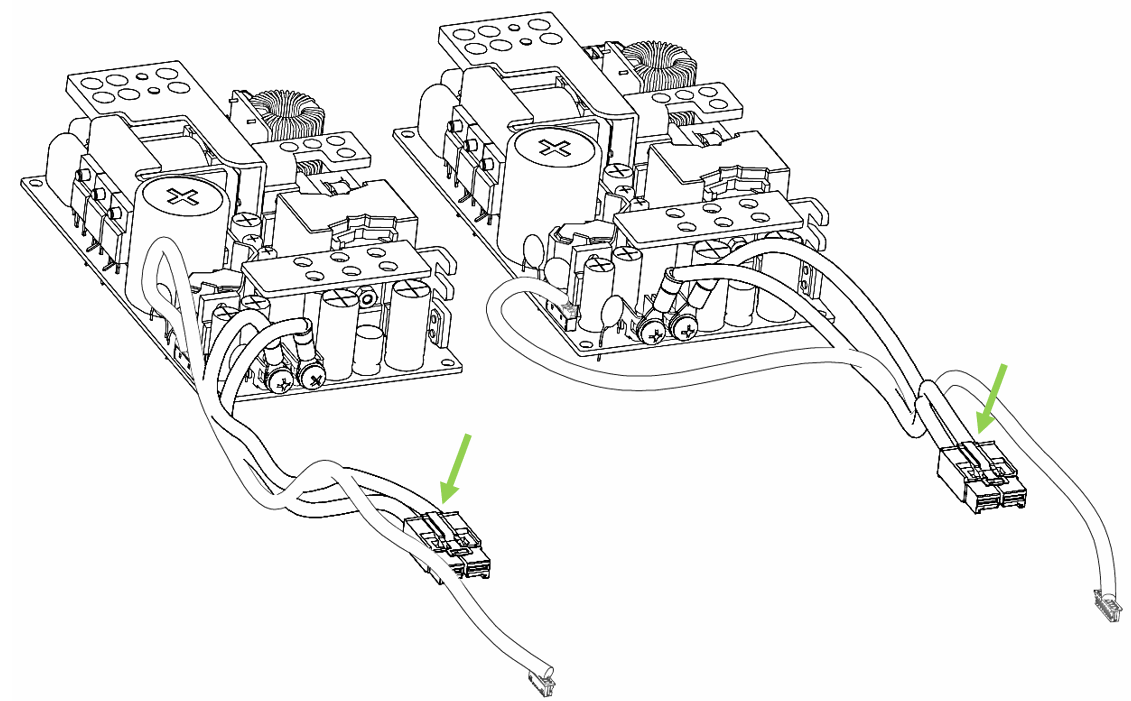
| 6. | Management board/X86 board: 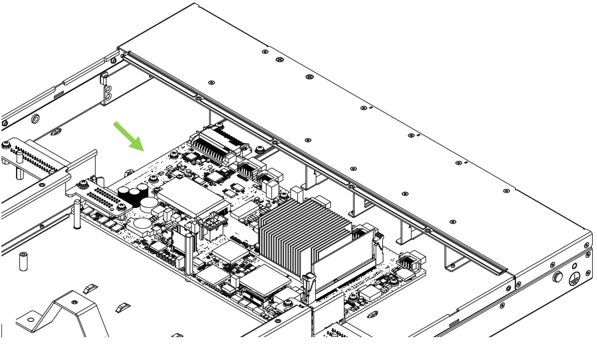
|
7. | Switch board: 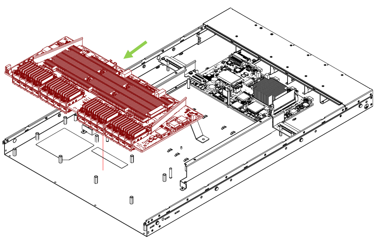
| 8. | Power supply unit extenders: 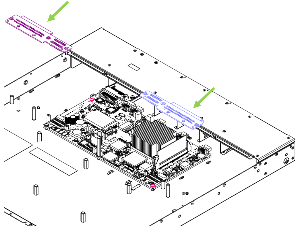
|
9. | AC inlet to power supply harness: 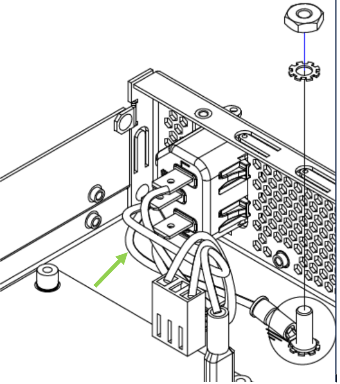
| 10. | Signal harness (from switch board to power supply): 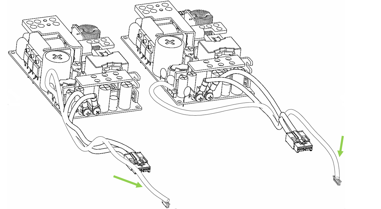
|
11. | I-O module: 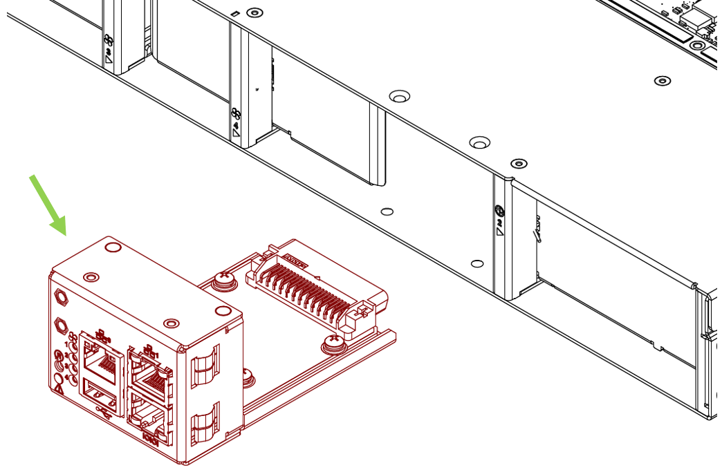
| 12. | SE flex PCB: 
|
13. | Switch board spacers: 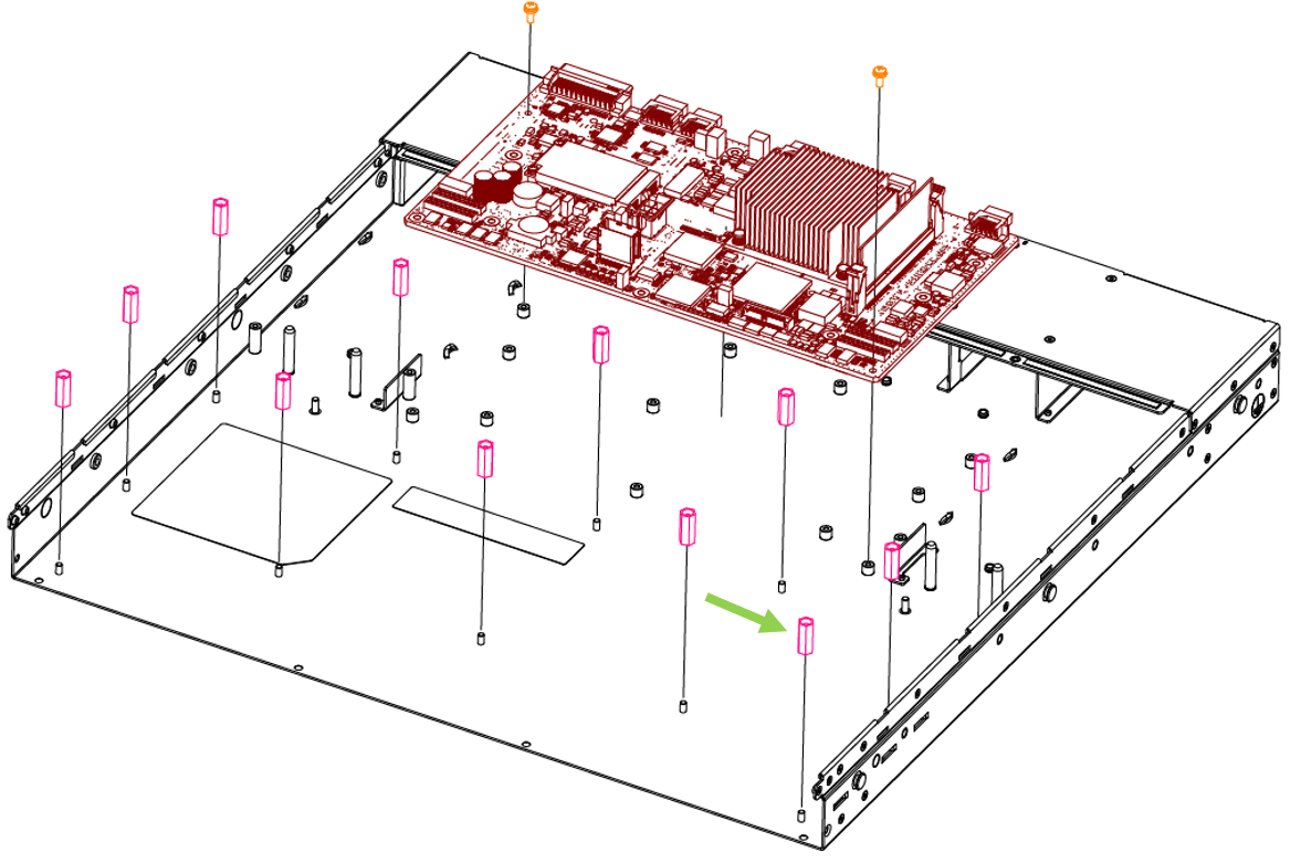
| 14. | PSU extender spacers: 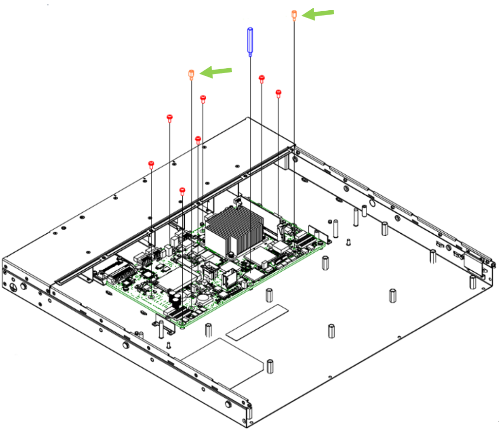
|
15. | Cable ties: 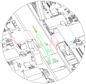
| 16. | Cable clamps: 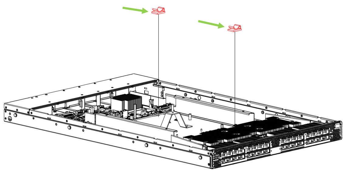
|
17. | Switch board cover stopper: 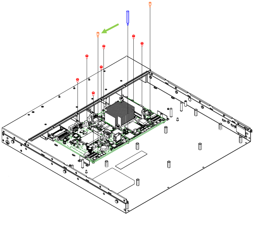
| 18. | Management board cover stopper: 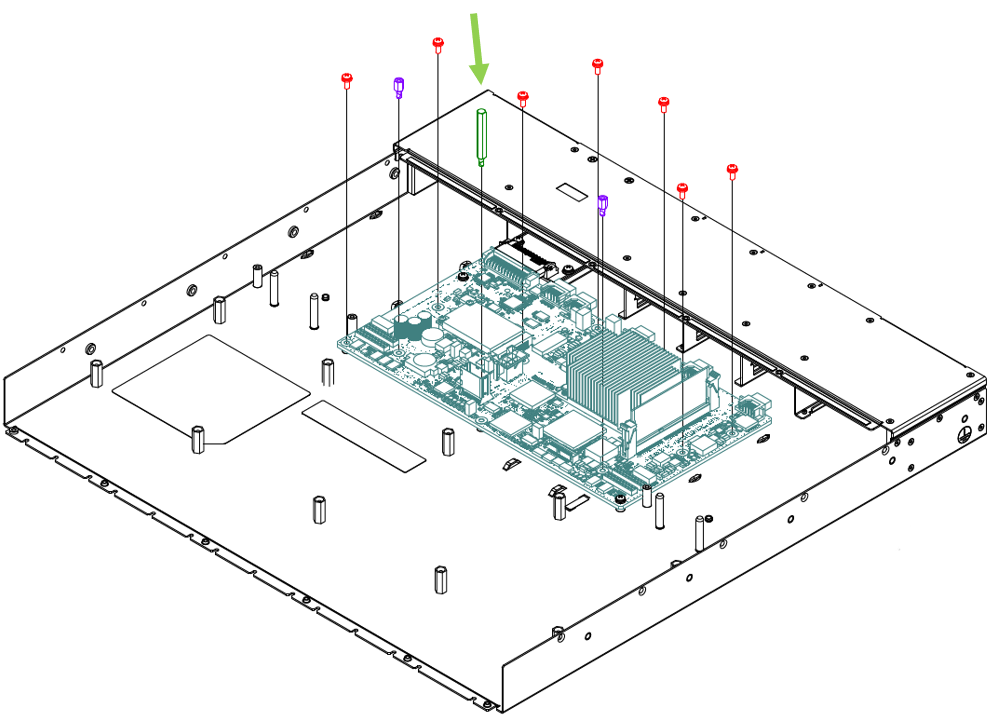
|
19. | DC cable between management board and switch board: 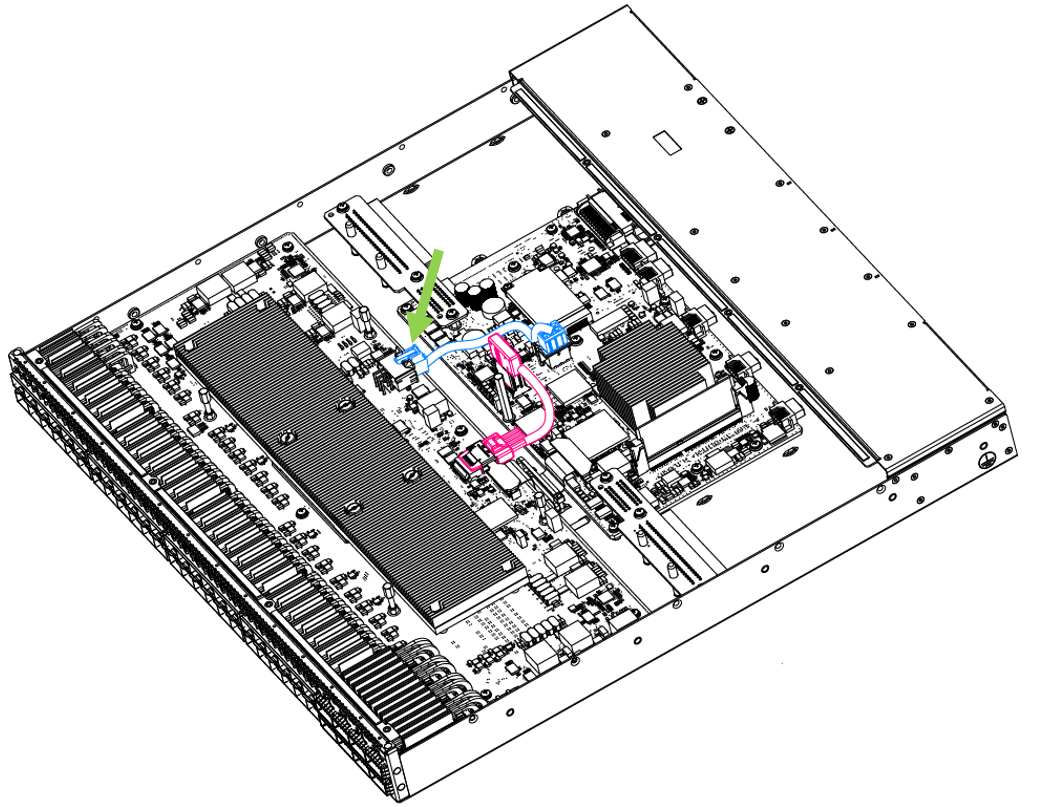
| 20. | LED divider: 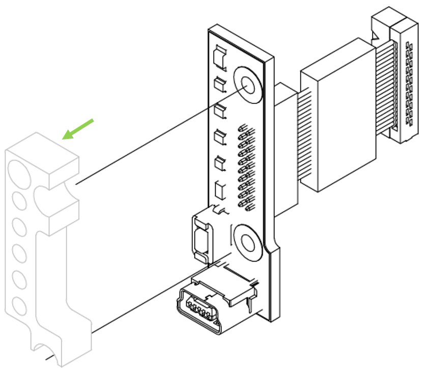
|
21. | Mini-SAS cable: 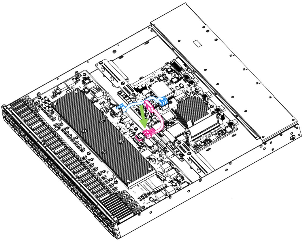
| 22. | Lexan label: 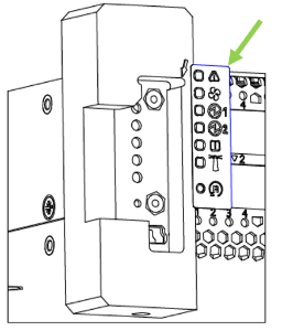
|
23. | Air buffers: 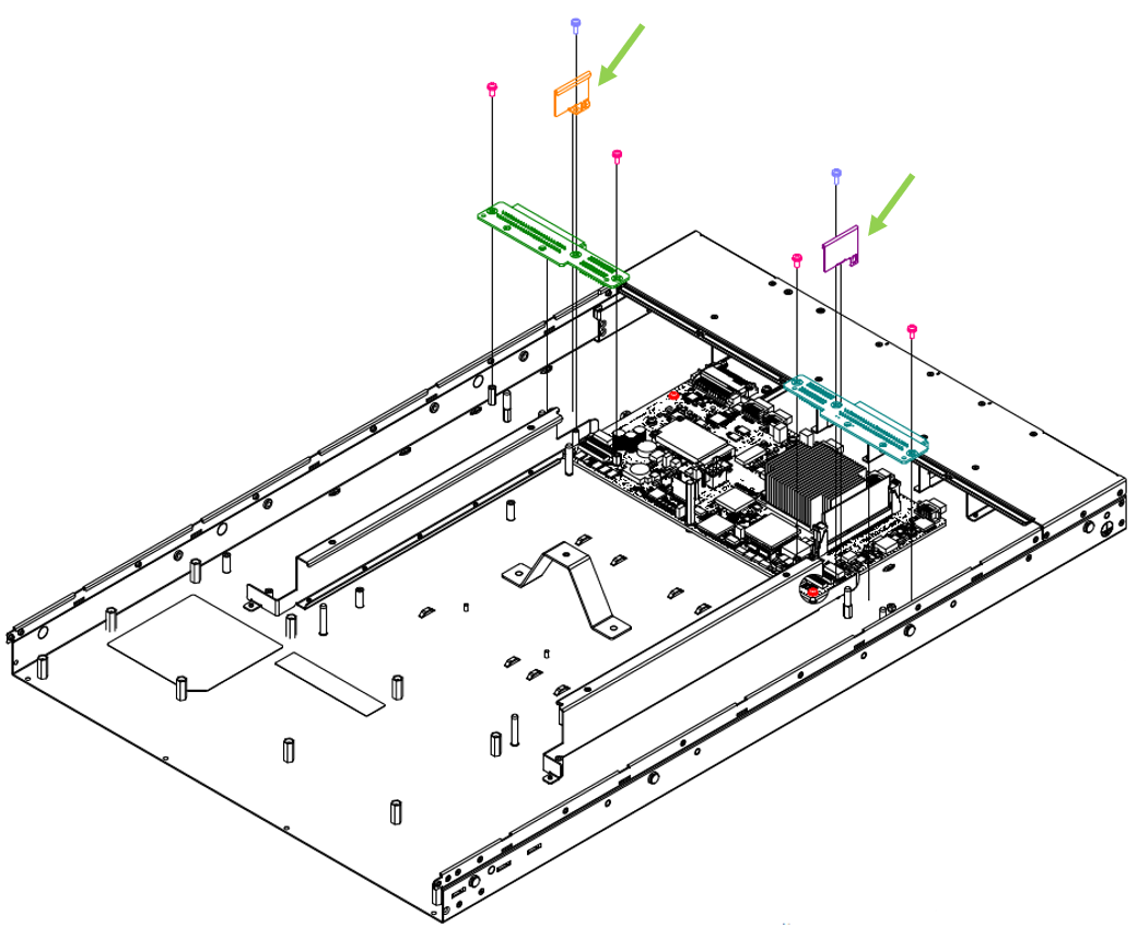
| 24. | Pull-tab: 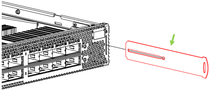
|