Specifications
The AOC has been qualified as an assembly and shall not be disassembled.
Absolute maximum ratings are those beyond which the device may be damaged.
|
Parameter |
Min |
Max |
Units |
|
Supply voltage |
-0.3 |
3.465 |
V |
|
Data input voltage |
-0.3 |
3.465 |
V |
|
Control input voltage |
-0.3 |
4.0 |
V |
This table shows the environmental specifications for the product.
|
Parameter |
Min |
Max |
Units |
|
Storage temperature |
-40 |
85 |
°C |
This section shows the range of values for normal operation. The host board power supply filtering should be designed as recommended in the SFF Committee Spec.
|
Parameter |
Min |
Typ |
Max |
Units |
|
Supply voltage (Vcc) |
3.145 |
3.3 |
3.465 |
V |
|
Power consumption (100GbE end no retiming) |
--- |
1.8 |
2.0 |
W |
|
Power consumption (100GbE retiming on all lanes) |
--- |
2.3 |
2.5 |
W |
|
Power consumption (50GbE end no retiming) |
--- |
1.2 |
1.3 |
W |
|
Power consumption (50GbE retiming on all lanes) |
--- |
1.5 |
1.7 |
W |
|
Supply noise tolerance (10 Hz – 10 MHz) |
66 |
mVpp |
||
|
Operating case temperature |
0 |
--- |
70 |
°C |
|
Operating relative humidity |
5 |
--- |
85 |
% |
|
Parameter |
Min |
Typ |
Max |
Units |
|
Signaling rate |
-100 ppm |
25.78125 |
+100 ppm |
Gb/s |
|
BER (Bit Error Rate)[1] |
--- |
--- |
10-15 |
--- |
|
Transmitter |
||||
|
Differential data input swing at TP1a |
According to IEEE 802.3bm |
--- |
900 |
mVpp |
|
Differential data output swing at TP4 |
--- |
--- |
480 |
mVpp |
|
Differential input return loss |
Meets equation (83E–5) in IEEE 802.3bm |
dB |
||
|
Differential output return loss |
Meets equation (83E–5) in IEEE 802.3bm |
dB |
||
|
Receiver |
||||
|
Common Mode output return loss |
--- |
--- |
-6 |
dB |
|
Output eye width (EW15) |
0.57 |
--- |
--- |
UI |
|
Output eye height (EH15) |
228 |
--- |
--- |
mV |
Notes: [1] BER performance was verified with a PRBS31 test pattern in accordance with the IEEE 802.3bm specifications, as part of the product qualification. [2] Requires optimization of the input equalizer.
For configurations tested with the AOCs please refer to the system level product quality assurance (SLPQA) report.
See LinkX® SFF Memory Map Application Note for details, reference [1].
|
Parameter |
Value |
Units |
|
Diameter |
3 +/- 0.2 |
mm |
|
Minimum bend radius |
30 |
mm |
|
Length tolerance |
Length < 5 m: +300 /-0 |
mm |
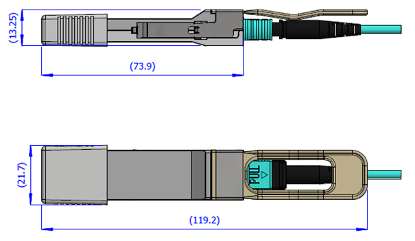
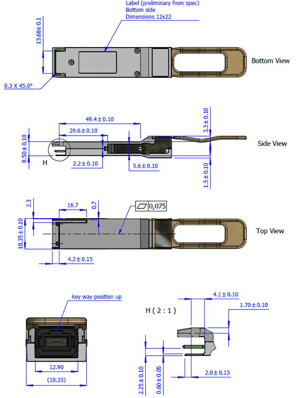
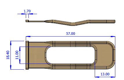
Mechanical Dimensions
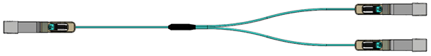
Cable Length Definition

Connectivity Schematic
|
100Gb/s Side |
2x50Gb/s Side |
|
Port 1 |
|
|
TX1 |
RX1 |
|
RX1 |
TX1 |
|
TX2 |
RX2 |
|
RX2 |
TX2 |
|
Port 2 |
|
|
TX3 |
RX1 |
|
RX3 |
TX1 |
|
TX4 |
RX2 |
|
RX4 |
TX2 |
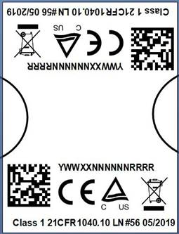
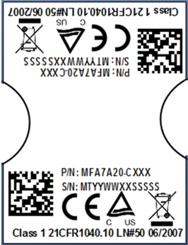
The following label is applied on the transceiver's backshell:
100GbE Backshell Label (New)
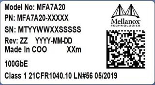
(sample illustration)
50GbE Backshell Label (New)
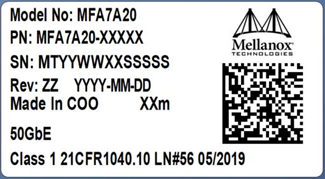
(sample illustration)
100GbE Backshell Label (Old)
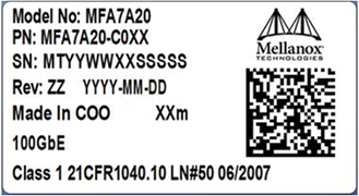
(sample illustration)
50GbE Backshell Label (Old)
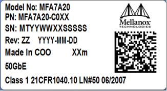
(sample illustration)
Images are for illustration purposes only. Product labels, colors, and lengths may vary.
Transceiver Backshell Label Serial Number Legend
|
Symbol |
Meaning |
Notes |
|
MT |
Manufacturer name |
2 digits (alphanumeric) |
|
YY |
Year of manufacturing |
2 last digits of the year (numeric) |
|
WW |
Week of manufacturing |
2 digit (numeric) |
|
XX |
Manufacturer site |
Two characters |
|
SSSSS |
Serial number |
5 digits (decimal numeric) for serial number, starting from 00001. |
The following label is applied on the cable’s jacket:
Cable Jacket Label (New)
(sample illustration)
Cable Jacket Label (Old)
(sample illustration)
Splitter Cable Labels Identifying the 2 QSFP28 Tails
(sample illustration)
The MFA7A20 is compatible with ESD levels in typical data center operating environments and certified in accordance with the standards listed in the Regulatory Compliance and Classification section below. The product is shipped with protective caps on its connectors to protect it until the time of installation. In normal handling and operation of high-speed cables and optical transceivers, ESD is of concern during insertion into the QSFP cage of the server/switch. Hence, standard ESD handling precautions must be observed. These include use of grounded wrist/shoe straps and ESD floor wherever a cable/transceiver is extracted/inserted. Electrostatic discharges to the exterior of the host equipment chassis after installation are subject to system level ESD requirements.
The laser module is classified as class I according to IEC 60825-1, IEC 60825-2 and 21 CFR 1040 (CDRH).
Safety: CB, cTUVus, CE
EMC: CE, FCC, ICES, RCM, VCCI
Ask your NVIDIA FAE for a zip file of the certifications for this product.
This equipment has been tested and found to comply with the limits for a Class A digital device, pursuant to part 15 of the FCC Rules. These limits are designed to provide reasonable protection against harmful interference when the equipment is operated in a commercial environment. This equipment generates, uses, and can radiate radio frequency energy and, if not installed and used in accordance with the instruction manual, may cause harmful interference to radio communications. Operation of this equipment in a residential area is likely to cause harmful interference in which case the user will be required to correct the interference at his own expense.