HowTo Configure RoCEv2 Lossless Fabric for VMware ESXi 6.5 and above
Created on Jun 9, 2019
Updated Mar 30, 2020
Introduction
This How To provides how to configure Priority Flow Control (PFC) a NVIDIA Spectrum installed with MLNX-OS and running RoCE over a lossless network, in PCP-based QoS mode.
This post assumes VMware ESXi 6.5/6.7 native and MLNX-OS version 3.6.5000 and above.
References
Hardware and Software Requirements
1. A server platform with an adapter card based on one of the following NVIDIA Technologies’ HCA devices:
ConnectX®-4 (EN) (firmware: fw-ConnectX4)
ConnectX-4 Lx (EN) (firmware: fw-ConnectX4-Lx)
ConnectX-5 (EN) (firmware: fw-ConnectX5)
ConnectX-5 Ex (EN) (firmware: fw-ConnectX5)
ConnectX-5 (VPI) (firmware: fw-ConnectX5)
2. Installer Privileges: The installation requires administrator privileges on the target machine.
3. Device ID: For the latest list of device IDs, please visit NVIDIA website.
Components Overview
RDMA over Converged Ethernet
From Wikipedia
RDMA over Converged Ethernet (RoCE) is a network protocol that allows remote direct memory access (RDMA) over an Ethernet network. There are two RoCE versions, RoCE v1 and RoCE v2. RoCE v1 is an Ethernet link layer protocol and hence allows communication between any two hosts in the same Ethernet broadcast domain. RoCE v2 is an internet layer protocol which means that RoCE v2 packets can be routed. Although the RoCE protocol benefits from the characteristics of a converged Ethernet network, the protocol can also be used on a traditional or non-converged Ethernet network.
Priority Flow Control (PFC)
Priority Flow Control (PFC) IEEE 802.1Qbb applies pause functionality to specific classes of traffic on the Ethernet link. The goal of this mechanism is to ensure zero loss under congestion in data center bridging(DCB) networks, and to allow, as a sample, for prioritization of RoCE traffic over TCP traffic. PFC can provide different levels of service to specific classes of Ethernet traffic (using IEEE 802.1p traffic classes).
Explicit Congestion Notification (ECN)
Explicit Congestion Notification (ECN) is an extension to the Internet Protocol and to the Transmission Control Protocol and is defined in RFC 3168 (2001). ECN allows end-to-end notification of network congestion without dropping packets. ECN is an optional feature that may be used between two ECN-enabled endpoints when the underlying network infrastructure also supports it.
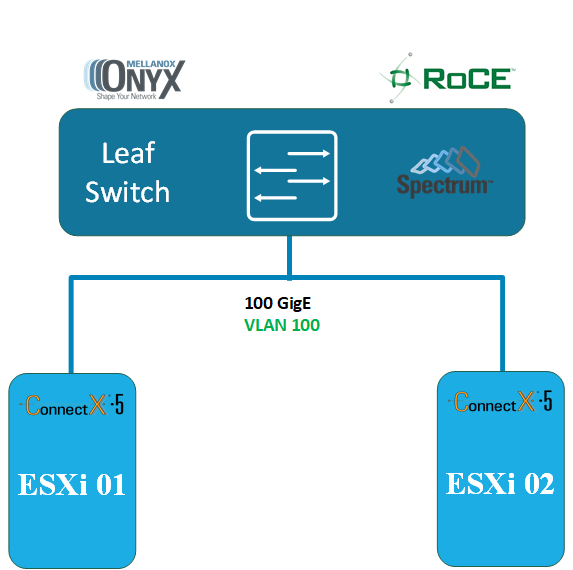
Setup Overview
Equipment
2x ESXi 6.5/6.7 hosts.
2x ConnectX®-3/ConnectX®-4/ConnectX®-4 Lx/ConnectX®-5, or any combination thereof.
1x NVIDIA Ethernet Spectrum Switch SN2700
Logical Design
Network Switch Configuration
Please start from the How-To Get Started with NVIDIA switches guide if you don't familiar with NVIDIA switch software.
For more information please refer to the MLNX-OS User Manual located at enterprise-support.nvidia.com/s/ or enterprise-support.nvidia.com/s/ → Switches
In first step please update your switch OS to the latest ONYX OS software. Please use this community guide How-To Upgrade MLNX-OS Software on NVIDIA switch systems.
There are several industry standard network configuration for RoCE deployment.
You are welcome to follow the Recommended Network Configuration Examples for RoCE Deployment for our recommendations and instructions.
In our deployment we will configure our network to be lossless and will use PCP or DSCP -based QoS mode on host and switch sides.
Switch Configuration
NVIDIA Onyx version 3.8.2004 and above.
Run:
Switch console
switch (config) #roce lossless
Note: The RoCE feature has been automated so that all that is needed (PFC+ECN) to run RoCE on lossless fabric is running the "roce" command.
To see RoCE configuration run:
Switch console
show roce
To monitor RoCE counters run:
Switch console
show interface ethernet counters roce
MLNX-OS version 3.6.5000 up to version 3.8.2004
Please run the following 5 steps:
A switch please configure your switch accordingly by following steps:
1. Please sure that MLNX-OS version 3.6.5000 up to version 3.8.2004 on your switch.
2. Enable ECN Marking.
Note: For a fair sharing of switch buffer with other traffic classes, it is recommended to configure ECN on all other traffic classes.
Switch Console
switch (config) # interface ethernet 1/1-1/32 traffic-class 3 congestion-control ecn minimum-absolute 150 maximum-absolute 1500
3. Create the RoCE pool and set QoS. Configure the traffic pool for RoCE.
Switch Console
            switch (config) # no advanced buffer management force
switch (config) # traffic pool roce type lossless
switch (config) # traffic pool roce memory percent 50.00
switch (config) # traffic pool roce map switch-priority 3
4. Set a strict priority to CNPs over traffic class 6
Switch Console
switch (config) # interface ethernet 1/1-1/32 traffic-class 6 dcb ets strict
5. Per port configuration
Set a QoS trust mode for the interface.
PCP only – tagged
Switch Console
switch (config) # interface ethernet 1/1 qos trust L2
DSCP only – non tagged IP frames
Switch Console
switch (config) # interface ethernet 1/1 qos trust L3
DSCP for non tagged , PCP for tagged
Switch Console
switch (config) # interface ethernet 1/1-1/32 qos trust both
Configure the switchport
Switch Console
            switch (config) # interface ethernet 1/1-1/32 switchport mode trunk
switch (config) # interface ethernet 1/1-1/32 switchport trunk allowed-vlan [vlan-id]
Switch configuration example
Below is our switch configuration you can use as reference with the QoS trust mode for the interface -DSCP only(default). You can copy/paste it to you switch but please be aware that this is clean switch configuration and if you may corrupt your existing configuration.
Switch Configuration Sample
            swx-vmw-1-1 [standalone: master] > enable
swx-wmv-1-1 [standalone: master] # configure terminal
swx-vmw-1-1 [standalone: master] (config) # show running-config

##
## Running database "initial"
## Generated at 2018/03/10 09:38:38 +0000
## Hostname: swx-vmw-1-1
##
##
## Running-config temporary prefix mode setting
##
no cli default prefix-modes enable
##
## License keys
##
license install LK2-RESTRICTED_CMDS_GEN2-44T1-4H83-RWA5-G423-GY7U-8A60-E0AH-ABCD
##
## Interface Ethernet buffer configuration
##
traffic pool roce type lossless
traffic pool roce memory percent 50.00
traffic pool roce map switch-priority 3
##
## QoS switch configuration
##
interface ethernet 1/1-1/32 qos trust L3
interface ethernet 1/1-1/32 traffic-class 3 congestion-control ecn minimum-absolute 150 maximum-absolute 1500
##
## DCBX ETS configuration
##
interface ethernet 1/1-1/32 traffic-class 6 dcb ets strict
##
## Other IP configuration
##
hostname swx-vmw-1-1
##
## AAA remote server configuration
##
# ldap bind-password ********
# radius-server key ********
# tacacs-server key ********
##
## Network management configuration
##
# web proxy auth basic password ********
##
## X.509 certificates configuration
##
#
# Certificate name system-self-signed, ID 108bb9eb3e99edff47fc86e71cba530b6a6b8991
# (public-cert config omitted since private-key config is hidden)
##
## Persistent prefix mode setting
##
cli default prefix-modes enable
Driver Configuration
Configure PFC
Configure PFC on NVIDIA drivers (mnlx drivers). Note that there is a different driver for each adapter. In this example we will enable PFC on priority 3 on the receive (Rx) and transmit (Tx).
The following command enables PFC on the host. The parameters, "pfctx" (PFC TX) and "pfcrx" (PFC RX), are specified per host. If you have more than a card on the server, all ports must be enabled with PFC.
The value is a bitmap of 8 bits = 8 priorities.
To run more than one flow type on the server, turn on only one priority (e.g. priority 3), which should be configured with the parameters "0x08" = 00001000b (binary). Only the 4th bit is on (starts with priority 0,1,2 and 3 -> 4th bit).
Note: When PFC is enabled, Global Pause will be operationally disabled, regardless of what is configured for the Global Pause Flow Control.
The values of “pfctx” and “pfcrx” must be identical.
If you configured SR-IOV, you need to Re-enable SR-IOV in the driver and set the max_vfs module parameter.
We recommend that you enable only lossless applications on a specific priority.
Configure trust mode to DSCP and enabling PFC allows running PFC based on the L3 DSCP field rather than the L2 PCP field. This will eliminate the need for VLAN in the Ethernet header.
Trust state has two values:
pcp - mapping pcp to priority. The default mapping is 1 to 1.
dscp - mapping dscp to priority. The default mapping is priority[dscp] = dscp>>3.
The default trust state is "pcp".
Examples:
ConnectX-3 specify(TM-mapping PCP to priority):
ESXi Console
~ esxcli system module parameters set -m nmlx4_en -p "pfctx=0x08 pfcrx=0x08 trust_state=1 max_vfs=4"
ConnectX-4/5 specify(TM-mapping DSCP to priority:
ESXi Console
~ esxcli system module parameters set -m nmlx5_core -p "pfctx=0x08 pfcrx=0x08 trust_state=2 max_vfs=4"
To read the current module configuration, run:
ConnectX-3:
ESXi Console
~ esxcli system module parameters list -m nmlx4_en
ConnectX-4/5:
ESXi Console
            ~ esxcli system module parameters list -m nmlx5_core
...
pfcrx int 0x08 Priority based Flow Control policy on RX.
Values : 0-255
It's 8 bits bit mask, each bit indicates priority [0-7]. Bit value:
1 - respect incoming pause frames on the specified priority.
0 - ignore incoming pause frames on the specified priority.
Notes: Must be equal to pfctx.
Default: 0
pfctx int 0x08 Priority based Flow Control policy on TX.
Values : 0-255
It's 8 bits bit mask, each bit indicates priority [0-7]. Bit value:
1 - respect incoming pause frames on the specified priority.
0 - ignore incoming pause frames on the specified priority.
Notes: Must be equal to pfcrx.
Default: 0
...
Configure Global RDMA PCP (L2 Egress Priority) and DSCP Values (L3-Optional)
The RMDA service level (sl) field for the address handles user priority and is mapped to the PCP portion of the VLAN tag.
The traffic class (tc) field of the address handles the GRH header and is mapped to the IP header DSCP bits.
You can force PCP and DSCP values (for RDMA traffic only).
The RDMA driver (nmlx5_rdma) supports global settings for the PCP (sl) and DSCP (traffic class) through the following module parameters:
pcp_force: values: (-1) - 7, default: (-1 = off)
The specified value will be set as the PCP for all outgoing RoCE traffic, regardless of the sl value specified. This parameter cannot be enabled when dscp_to_pcp is enabled.
dscp_force: values: (-1) - 63, default: (-1 = off)
The specified value will be set as the DSCP portion (6 bits) of the Type of Service (ToS) (8 bits) for all outgoing RoCE traffic, regardless of the traffic class specified.
dscp_to_pcp: values 0 (off) - 1 (on), default: 0
When enabled, the three MSBs of the DSCP value will be considered as the PCP for all outgoing RoCE traffic. If dscp_force is not used, then the DSCP value used for mapping is taken from the traffic class field in the GRH header. Otherwise, it takes the value set in dscp_force.
This parameter cannot be enabled when pcp_force is enabled.
Log into a ESXi vSphere Command-Line Interface with root permissions.
For example, to force the PCP value to egress with a value of 3:
ConnectX-3:
ESXi Console
# esxcli system module parameters set -m nmlx4_rdma -p "pcp_force=3"
ConnectX-4/5:
ESXi Console
            # esxcli system module parameters set -m nmlx5_rdma -p "pcp_force=3"

Name Type Value Description
----------------- ---- ----- ---------------------------------------------------------------------------------------------------------------------------------------------------------------------
dscp_force int DSCP value to force on outgoing RoCE traffic.
Values : -1 - Disabled, 0-63 - DSCP value to force
Default: -1
dscp_to_pcp int Map the three MSBs of DSCP value to PCP on outgoing RoCE traffic.
Cannot be enabled when pcp_force is active.
Values : 0 - Disabled, 1 - Enabled
Default: 0
enable_nmlx_debug int Enable debug prints.
Values : 1 - enabled, 0 - disabled
Default: 0
pcp_force int 3 PCP value to force on outgoing RoCE traffic.
Cannot be active when dscp_to_pcp is enabled.
Values : -1 - Disabled, 0-7 - PCP value to force
Default: -1
For example, to configure the DSCP(Optional):
ConnectX-3:
ESXi Console
# esxcli system module parameters set -m nmlx4_rdma -p "dscp_force=26"
ConnectX-4/5:
ESXi Console
# esxcli system module parameters set -m nmlx5_rdma -p "dscp_force=26"
Configure ECN
For enable ECN with default parameters.
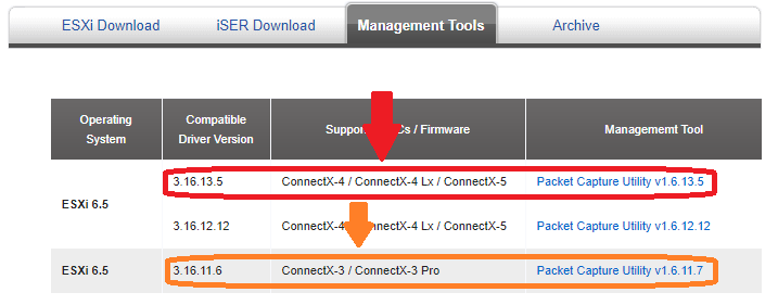
1. Download a latest NVIDIA NVIDIA Packet Capture Utility for ESXi 6.5/6.7.
2. Use SCP or any other file transfer method to copy the driver to the required ESXi host.
3. Log into a ESXi vSphere Command-Line Interface with root permissions.
4. Enter Maintenance Mode the ESXi host.
5. Install the Packet Capture Utility on ESXi host.
Sample:
ESXi Console
~ esxcli software vib install -d /tmp/MLNX-NATIVE-NMLXCLI_1.17.13.8-10EM-670.0.0.7535516.zip
6. Reboot the ESXi server.
7. Check physical network interface status.
ESXi Console
            ~ esxcli network nic list

Name PCI Device Driver Admin Status Link Status Speed Duplex MAC Address MTU Description

------ ------------ ---------- ------------ ----------- ------ ------ ----------------- ---- ----------------------------------------------------

vmnic0 0000:81:00.0 igbn Up Up 1000 Full 0c:c4:7a:e3:5c:8c 1500 Intel Corporation I350 Gigabit Network Connection

vmnic1 0000:81:00.1 igbn Up Down 0 Half 0c:c4:7a:e3:5c:8d 1500 Intel Corporation I350 Gigabit Network Connection

...

vmnic4 0000:02:00.1 nmlx5_core Up Down 0 Half ec:0d:9a:8c:c7:97 1500 Mellanox Technologies MT28800 Family [ConnectX-5 Ex]

vmnic5 0000:02:00.0 nmlx5_core Up Up 100000 Full ec:0d:9a:8c:c7:96 1500 Mellanox Technologies MT28800 Family [ConnectX-5 Ex]
8. Enable ECN on relevant device.
ConnectX-3/4/5:
ESXi Console
            ~ esxcli mellanox uplink ecn rRoceNp enable -u vmnic5

~ esxcli mellanox uplink ecn rRoceRp enable -u vmnic5
9. Exit Maintenance Mode the ESXi host.
ESXi VLAN Configuration
The topology below describes two machines. Both of them have vmnic5 as the adapter uplink.
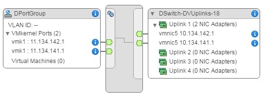
To set the VLAN ID for the traffic to 100, run:
1. Edit the distributed port group settings.
2. Choose "VLAN" from the left panel.
3. Set the VLAN type to "VLAN".
4. Set the VLAN tag to "100".
5. Click "OK".
For more information refer to VMware documentation.
Verification
Log into a ESXi vSphere Command-Line Interface with root permissions.
For verification purposes, when you are using NVIDIA switches you can lower the speed of one of the switch ports, forcing the use of PFC pause frames due to insufficient bandwidth:
Switch Console
            switch (config) # interface ethernet 1/1 shutdown
switch (config) # interface ethernet 1/1 speed 10000
switch (config) # no interface ethernet 1/1 shutdown
Note: You can create congestion to force PFC to be enabled using other methods. For example, you can use two hosts to send traffic to a third host, which is a simple configuration.
Run traffic between the hosts on priority 3.
Note: The final PCP values will be decided by the pcp_force.
Note: If PFC for a priority is not enabled by pfctx and pfcrx, the HCA counters for that priority will not increment, and the data will be counted on priority 0 instead.
See that both the HCA and switch transmitted/received pause frames on priority 3:
            # vish -e cat /net/pNics/vmnic5/stats | grep -e "Pause\|PerPrio"

PerPrio[0]
rxPause : 0
txPause : 0
PerPrio[1]
rxPause : 0
txPause : 0
PerPrio[2]
rxPause : 0
txPause : 0
PerPrio[3]
rxPause : 3348591
txPause : 12217
PerPrio[4]
rxPause : 0
txPause : 0
PerPrio[5]
rxPause : 0
txPause : 0
PerPrio[6]
rxPause : 0
txPause : 0
PerPrio[7]
rxPause : 0
txPause : 0
Done !
Authors
|

|
Boris Kovalev Boris Kovalev has worked for the past several years as a Solutions Architect, focusing on NVIDIA Networking/Mellanox technology, and is responsible for complex machine learning, Big Data and advanced VMware-based cloud research and design. Boris previously spent more than 20 years as a senior consultant and solutions architect at multiple companies, most recently at VMware. He has written multiple reference designs covering VMware, machine learning, Kubernetes, and container solutions which are available at the Mellanox Documents website. |