RDG for Bare Metal GPU-Accelerated HPC and AI Workloads on OpenStack Cloud over InfiniBand Fabric
Created on Feb 10, 2022
Abbreviations and Acronyms
|
Term |
Definition |
Term |
Definition |
|
AI |
Artificial Intelligence |
IPoIB |
IP over InfiniBand |
|
BM |
Bare Metal |
MLNX_OFED |
NVIDIA OpenFabrics Enterprise Distribution for Linux (network driver) |
|
BOM |
Bill of Materials |
OC |
Overcloud |
|
CUDA |
Compute Unified Device Architecture |
OS |
Operating System |
|
DIB |
Disk Image Builder |
PKey |
Private Key |
|
DHCP |
Dynamic Host Configuration Protocol |
RDG |
Reference Deployment Guide |
|
GPU |
Graphics Processing Unit |
RDMA |
Remote Direct Memory Access |
|
HA |
High Availability |
RDO |
RPM Distribution of OpenStack |
|
HDR |
High Data Rate - 200Gb/s |
SDN |
Software Defined Networking |
|
HPC |
High Performance Computing |
TripleO |
OpenStack On OpenStack |
|
IB |
InfiniBand |
UFM |
Unified Fabric Manager |
|
IPMI |
Intelligent Platform Management Interface |
VLAN |
Virtual LAN |
|
UFM |
Unified Fabric Manager |
References
Introduction
The OpenStack cloud operating system includes support for Bare Metal cloud services using GPUs over an InfiniBand network. This allows a multi-tenant, secure accelerated Bare Metal cloud deployment that provides best-in-class performance for HPC and AI workloads.
The following Reference Deployment Guide (RDG) demonstrates a complete deployment of OpenStack Bare Metal Cloud for HPC/AI multi-tenant workloads accelerated by NVIDIA® GPUs, Adapters, and Quantum InfiniBand fabric. The RDG covers a single-rack reference deployment that could easily scale up to multi-rack solution.
This RDG includes a solution design, scale considerations, hardware BoM (Bill of Materials) and the complete list of steps to provision Bare Metal tenant instances over InfiniBand fabric and perform GPUDirect-RDMA infrastructure bandwidth testing.
The solution below is based on OpenStack RDO ("Wallaby" Release) as a cloud platform with integrated InfiniBand support deployed using TripleO software.
Solution Architecture
Key Components and Technologies
NVIDIA A100 Tensor Core GPU delivers unprecedented acceleration at every scale to power the world’s highest-performing elastic data centers for AI, data analytics, and HPC. Powered by the NVIDIA Ampere Architecture, A100 is the engine of the NVIDIA data center platform. A100 provides up to 20X higher performance over the prior generation and can be partitioned into seven GPU instances to dynamically adjust to shifting demands.
ConnectX®-6 InfiniBand adapter cards are a key element in the NVIDIA Quantum InfiniBand platform. ConnectX-6 provides up to two ports of 200Gb/s InfiniBand connectivity with extremely low latency, high message rate, smart offloads, and NVIDIA In-Network Computing acceleration that improve performance and scalability.
The NVIDIA Quantum InfiniBand switches provide high-bandwidth performance, low power, and scalability. NVIDIA Quantum switches optimize data center connectivity with advanced routing and congestion avoidance capabilities.
The LinkX® product family of cables and transceivers provides complete connectivity matrix for InfiniBand data center infrastructures.
NVIDIA® UFM® (Unified Fabric Manager) platforms revolutionize data center networking management by combining enhanced, real-time network telemetry with AI-powered cyber intelligence and analytics to support scale-out InfiniBand data centers.
OpenStack is the most widely deployed open-source cloud software in the world. As a cloud operating system, it controls large pools of compute, storage, and networking resources throughout a datacenter, all managed and provisioned through APIs with common authentication mechanisms. Beyond standard infrastructure-as-a-service (Iaas) functionality, additional components provide orchestration, fault management and service management amongst other services, to ensure high availability of user applications.
RDO (RPM Distribution of OpenStack) is a freely available community-supported distribution of OpenStack originated by Red Hat. RDO runs on CentOS, Red Hat Enterprise Linux (RHEL) and Fedora, and makes the latest OpenStack development release available for use.
Logical Design
Below is an illustration of the solution's logical design.
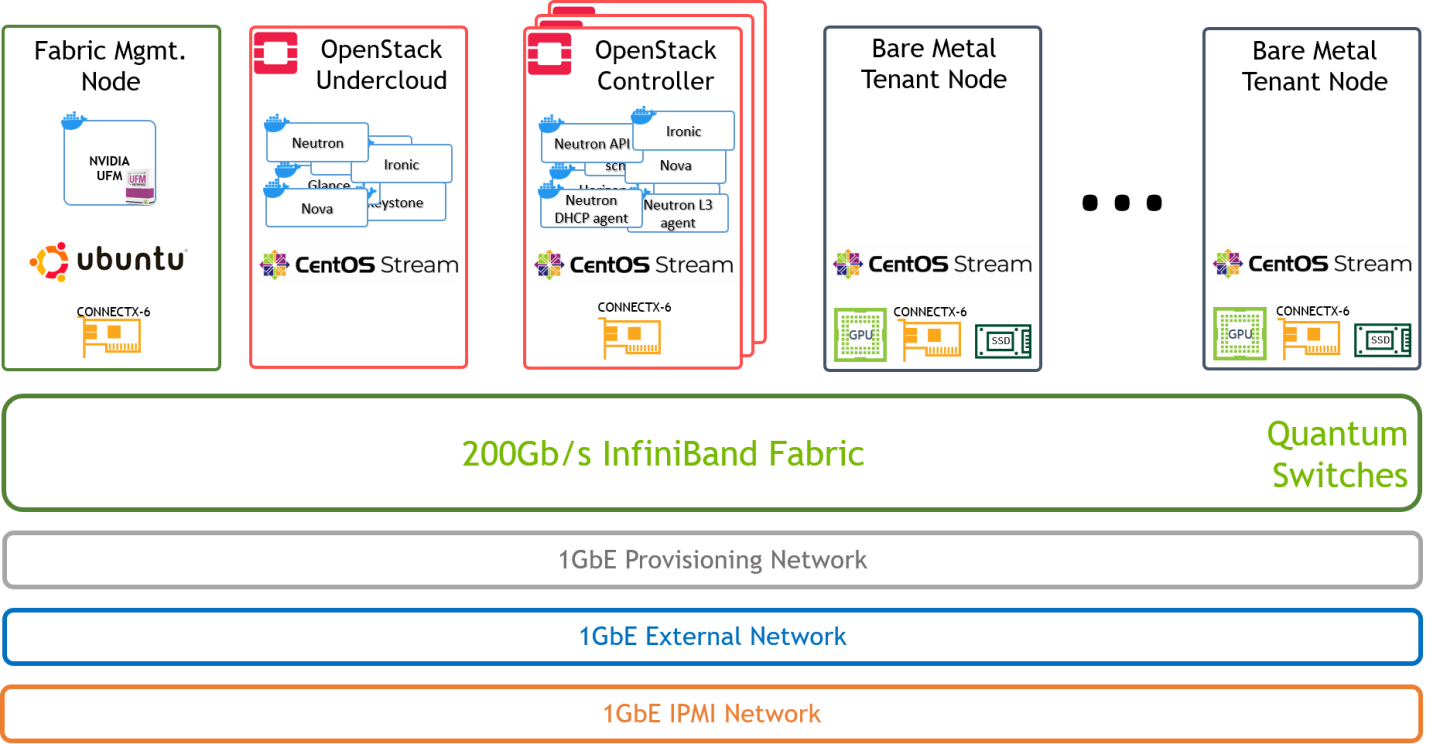
Single 200Gb/s InfiniBand fabric is used for both tenant and OpenStack control networks.
Neutron components (api/dhcp/l3) include the required code to support InfiniBand on the Controller node
Network Design
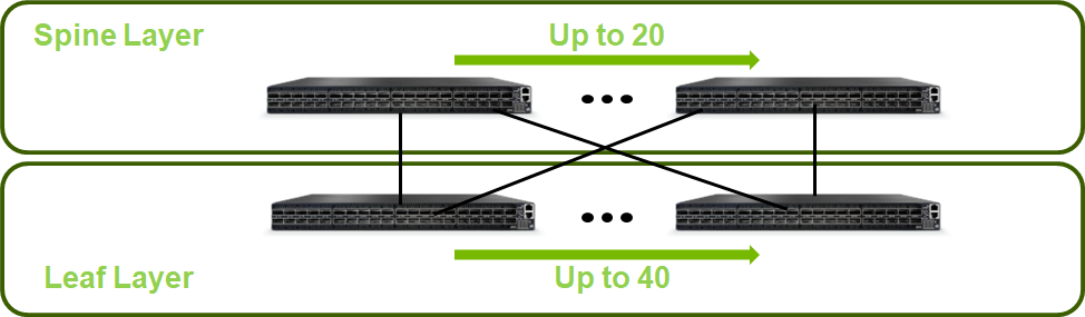
Network Topology
Below is an illustration of the solution's fabric topology.
Reference Architecture Scale
Initial Setup for a One Switch Solution:
Single rack
1 x NVIDIA Quantum QM8700 200G InfiniBand Switch
3 x Controller Nodes
2 x Bare Metal Tenant Nodes
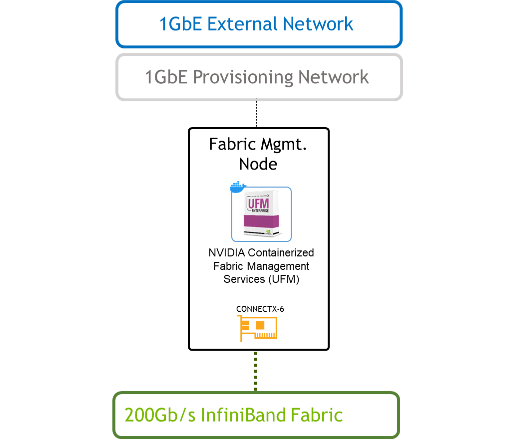
1 x Fabric Management Node
1 x 1GbE Switch (for multiple 1GbE networks isolated with VLANs)
Scaled Setup for a Two-Layer Fat-Tree Topology:
This deployment scenario scales up to 20 Spine switches and 40 Leaf switches, and supports up to 800 servers.
NoteScale considerations refer to high speed InfiniBand fabric only and do not cover provisioning, IPMI and External networks.
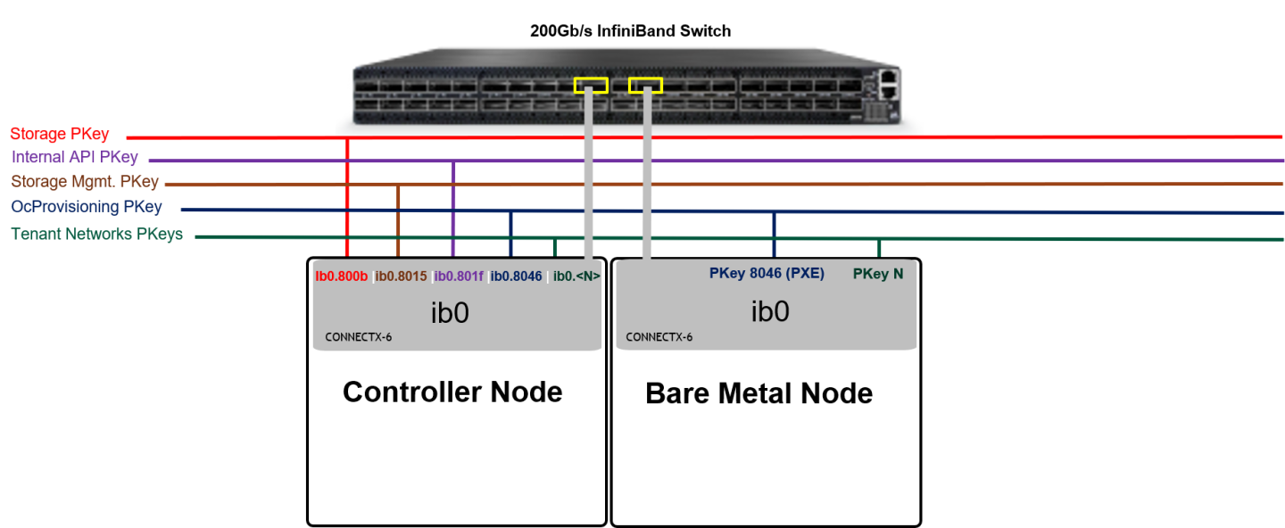
Host Design
Tenant Isolation
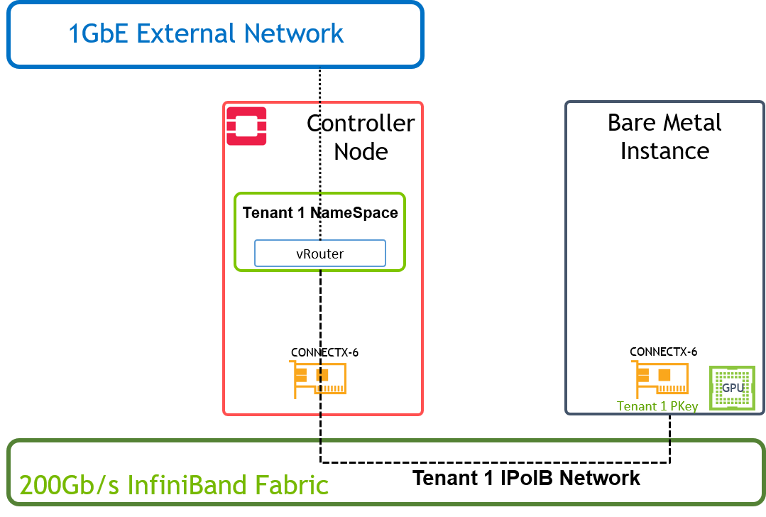
Below is an illustration of the solution's host design.
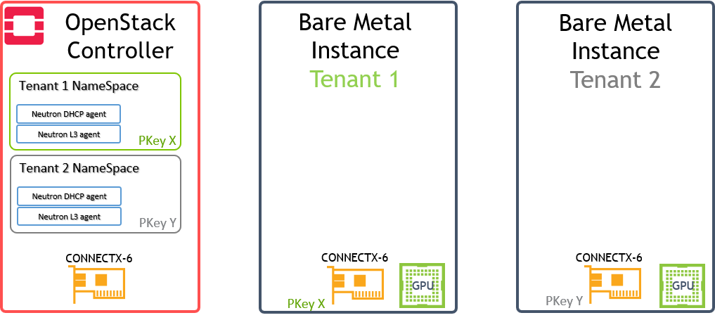
PKey is used to isolate the Bare Metal instances traffic on the tenant network they belong to.
Tenant NameSpaces include DHCP server / vRouter (L3 Agent) with IPoIB support and configured with a PKey to isolate the traffic on the tenant network they belong to.
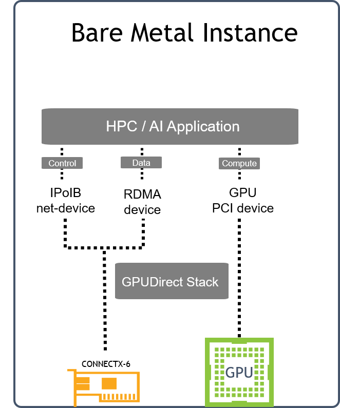
Application Logical Design
Software Stack Components
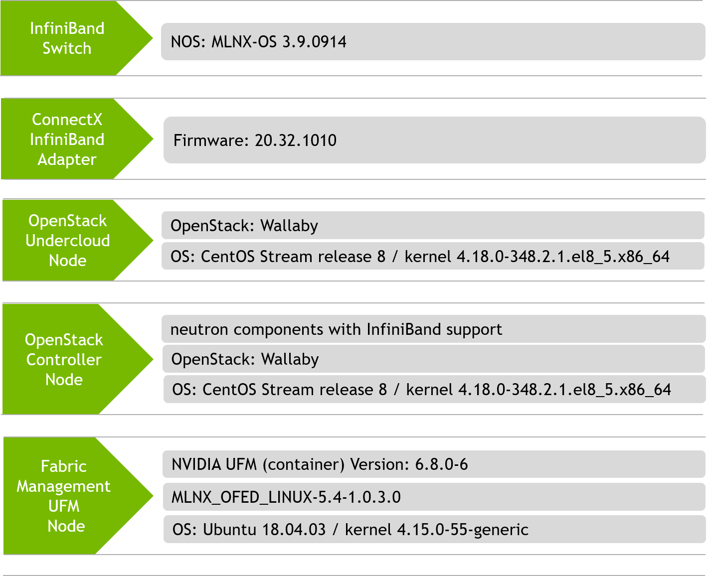
Bill of Materials (BoM)
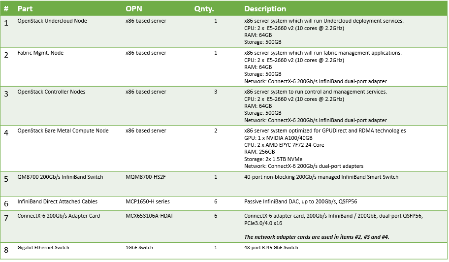
The BoM above refers to 1xRack based reference architecture.
Solution Configuration and Deployment
Physical Wiring
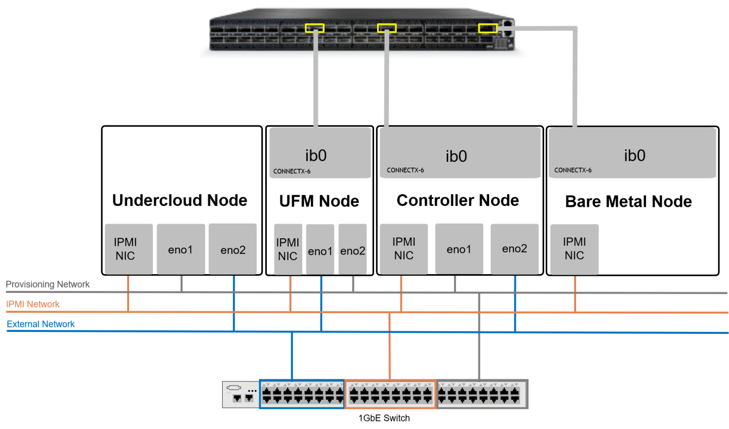
When using a dual-port InfiniBand host channel adapter (HCA), only the first port should be wired to the fabric.
From the OS perspective, the network device ib0 will be used for IPoIB traffic.
The Provisioning network is used for Overcloud Nodes deployment by the Undercloud, and the OcProvisioning network is used for Bare Metal Tenant Nodes deployment by the Overcloud Controller Nodes.
A single 1GbE Switch was used in this case for multiple 1GbE networks isolated with VLANs.
The UFM Node is connected to the External network in order to pull the UFM application container from the internet. It is also possible to use local images without internet connectivity.
Connect all nodes to the IPMI network.
Connect the IB Switch Mgmt. port to the OpenStack Provisioning network and allocate an IP address outside of the Overcloud nodes range.
Connect the UFM Node to OpenStack Provisioning network and allocate an IP address outside of the Overcloud nodes range.
Connect the UFM Node, the Overcloud nodes (Controller nodes) and the Bare Metal nodes to the IB Fabric.
Connect the OpenStack Undercloud and Overcloud nodes (Controller nodes) to the OpenStack Provisioning network.
Connect the Undercloud, Controllers, and UFM nodes to the External (Public) network.
IPoIB Fabric Configuration
|
Network Name |
Network Details |
PKey ID |
|
Storage |
172.16.0.0 / 24 |
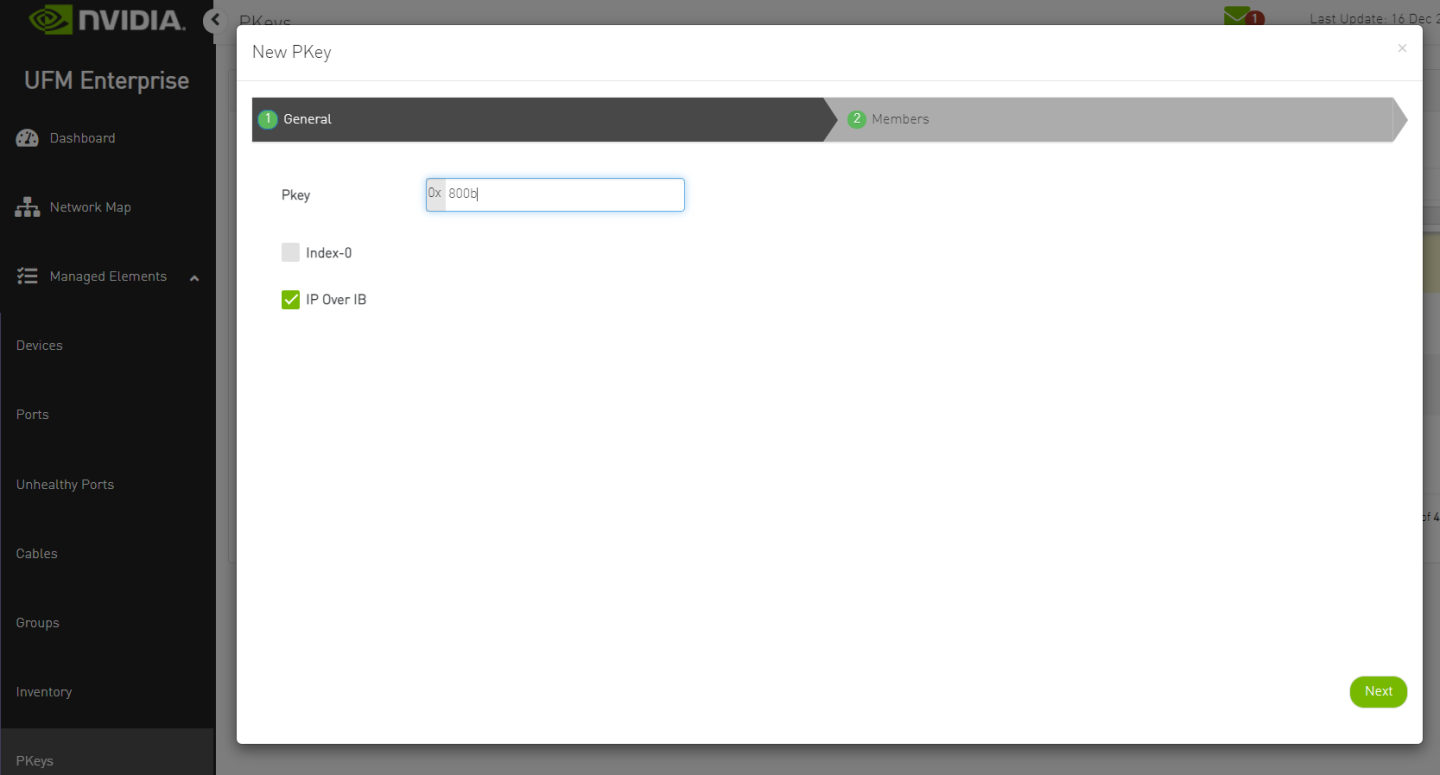
800b |
|
Storage_Mgmt |
172.17.0.0 / 24 |
8015 |
|
Internal API |
172.18.0.0 / 24 |
801f |
|
OcProvisioning |
172.70.0.0/24 |
8046 |
|
Tenant VLAN <N> |
Created by Tenant |
80<Hex_N> |
In Ethernet OpenStack deployments, VLANs can be used for tenant isolation. In InfiniBand, Partition Keys (PKeys) are used to gain tenant isolation.
Tenant network VLAN ID "N" is mapped to tenant PKey "80<Hex_N>". In this RDG we use tenant VLAN ID 101 which is converted to PKey 0x8065.
Host Configuration
Prerequisites
Hardware specifications are identical for servers with the same role (Controller Nodes/Bare Metal Nodes, etc.)
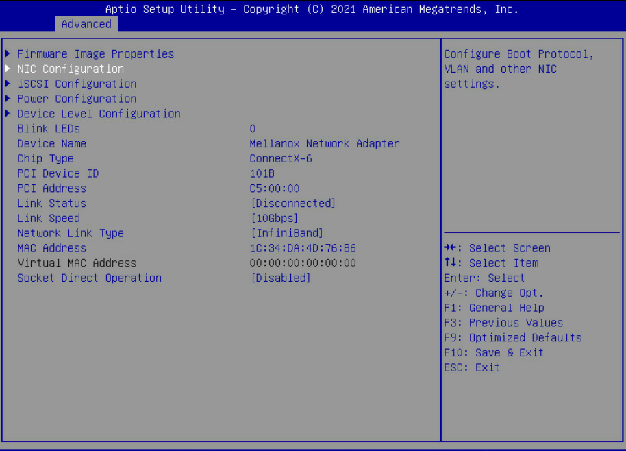
All ConnectX-6 Adapters ports used in Controller, Bare Metal and Fabric Management nodes should be set to operate in InfiniBand mode (default).
Bare Metal Nodes BIOS should be configured with the following:
UEFI mode
For GPUDirect usage - Virtualization and SR-IOV should be disabled
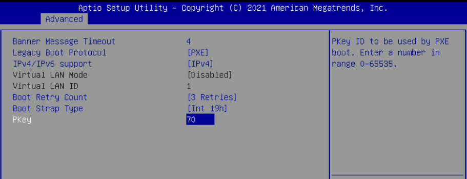
PXE boot is set in server boot order
Adapter PXE is enabled and PKey is matching the OpenStack provisioning network VLAN ID ("70" in the example used in this article)
Fabric Management Node (UFM) Installation
The "Fabric Management" is a Linux-based host running UFM Enterprise application container.
In this article, a single Fabric Management node is deployed. High Availability deployment is possible, however, not covered.
For UFM Enterprise User Manual refer to this link.
For UFM Enterprise Docker Container Installation Guide refer to this link.
Using NVIDIA UFM Enterprise Software requires a license - please contact NVIDIA Networking Support.
Fabric Management Node OS
Install the OS on the Fabric Mgmt Node. (In this solution we have used Ubuntu 18.04 OS).
Install NVIDIA MLNX_OFED network drivers. For further information refer to this link.
Install and enable Docker service—Ubuntu Docker Installation.
Use the "ibstat" command to make sure the Fabric Management Node is connected to the InfiniBand Fabric, and the link is up.
Make sure the Fabric Management Node is connected to the OpenStack provisioning network and allocate an IP Address outside of the Overcloud nodes range. In our example we have assigned IP 192.168.24.200 to this node.
Set a dummy IP address on the InfiniBand ib0 interface and make sure it is in "up" state. This step is a prerequisite for UFM application installation.
Noteib0 is the default fabric interface used by UFM installer. If you connected ib1 to the InfiniBand fabric, make sure to specify the interface during UFM installer execution.
Make sure External access is available as it will be used to pull the UFM application container from the internet. It is also possible to use local images without internet connectivity.
UFM Enterprise Application Container
Additional information about UFM Container installation is available here.
Create a host directory to store the UFM application configuration.
# mkdir -p /var/ufm_files/
Create a host directory to store the UFM application license, and place the license there.
# mkdir -p /home/ubuntu/UFM_lic/
Make sure internet access is available and pull the UFM Enterprise Installer image from the Docker hub repository.
# docker pull mellanox/ufm-enterprise-installer:latest
Run the Installer application container with the local directory mapped, and verify it is up.
NoteFor all installer options and default values issue the following command: "docker run --rm mellanox/ufm-enterprise-installer:latest -h"
The Installer container will bring up a UFM Enterprise application container named "ufm" and will terminate.
            # docker run -it --name=ufm_installer --rm \
-v /var/run/docker.sock:/var/run/docker.sock \
-v /var/ufm_files/:/installation/ufm_files/ \
-v /home/ubuntu/UFM_lic/:/installation/ufm_licenses/ \
mellanox/ufm-enterprise-installer:latest
            Deployment Mode [install/upgrade]:   install
UFM Mode [SA/HA]:                    SA
UFM Enterprise Image:                mellanox/ufm-enterprise:latest
UFM Files Path:                      /var/ufm_files/
UFM License Path:                    /home/ubuntu/UFM_lic/
Fabric Interface:                    ib0
Management Interface:                eth0
Loading UFM Enterprise Image...
latest: Pulling from mellanox/ufm-enterprise
2d473b07cdd5: Pull complete
239fbdbd6064: Pull complete
a25becc1a642: Pull complete
Digest: sha256:05e5341c9edaff55450841852e1657fa4f032d0f29898f5b978663d404ab9470
Status: Downloaded newer image for mellanox/ufm-enterprise:latest
docker.io/mellanox/ufm-enterprise:latest
Creating UFM Enterprise Container...
6efbfd1142b7088533474449e66afb1ca55d5c4838cfd0776213f00f2ad6ba46
UFM Container Created
Copying UFM Configuration Files...
Copying License File...
ufm
[*] Starting UFM Container
ufm
UFM Container started. You can check UFM status by running:
docker exec -it ufm /etc/init.d/ufmd status
============================================================================================
   UFM container installation finished successfully
============================================================================================
Verify the UFM Enterprise application container is up and the UFM service is running.
            # docker ps -a
CONTAINER ID   IMAGE                            COMMAND                  CREATED         STATUS         PORTS     NAMES
6efbfd1142b7   mellanox/ufm-enterprise:latest   "sh /usr/sbin/docker…"   7 minutes ago   Up 7 minutes             ufm

# docker exec -it ufm /etc/init.d/ufmd status
ufmd status
ufmd (pid 622) is running...
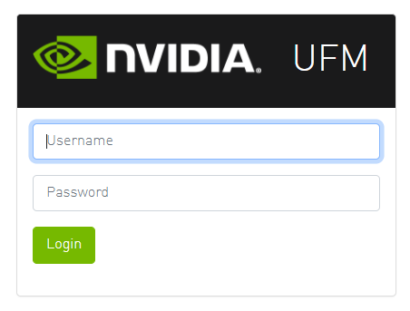
Connect from a client on the External or the Provisioning networks to the UFM WebUI using the following URL.
NoteDefault Login Credentials: admin/123456
https://192.168.24.200/ufm/
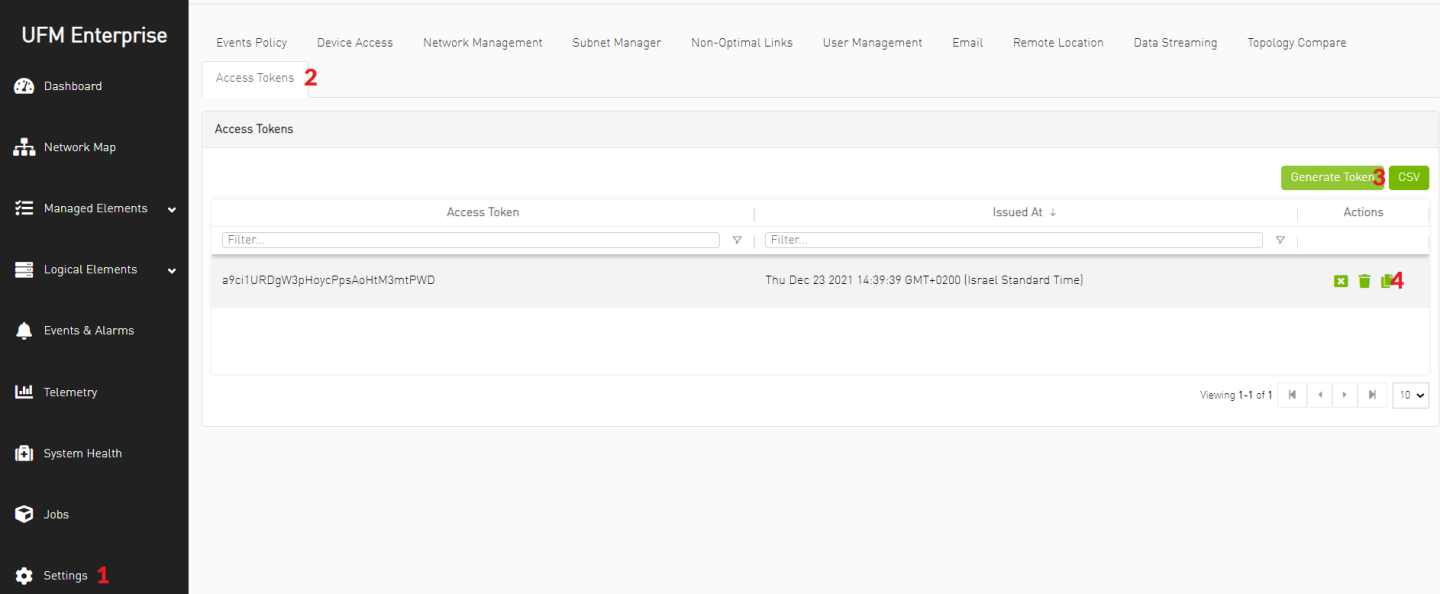
Generate UFM API Access Token and copy it for later usage.
NoteThe token will be used in OpenStack Overcloud deployment file neutron-ml2-mlnx-sdn-bm.yaml
OpenStack Undercloud Node Preparation and Installation
In the solution below we use RDO OpenStack Deployment using TripleO.
Follow the Undercloud Installation procedure described here up to "Prepare the configuration file" section. The following components were used:
CentOS Stream release 8 OS with 100GB root partition
"Wallaby" OpenStack Release TripleIO repositories
$ sudo -E tripleo-repos -b wallaby current
Undercloud configuration file "undercloud.conf"
undercloud.conf
            [DEFAULT]
undercloud_hostname = rdo-director.localdomain
local_ip = 192.168.24.1/24
network_gateway = 192.168.24.1
undercloud_public_host = 192.168.24.2
undercloud_admin_host = 192.168.24.3
undercloud_nameservers = 10.7.77.192,10.7.77.135
undercloud_ntp_servers = 10.211.0.134,10.211.0.124
subnets = ctlplane-subnet
local_subnet = ctlplane-subnet
generate_service_certificate = True
certificate_generation_ca = local
local_interface = eno1
inspection_interface = br-ctlplane
undercloud_debug = true
enable_tempest = false
enable_telemetry = false
enable_validations = true
enable_novajoin = false
clean_nodes = true
container_images_file = /home/stack/IB/containers-prepare-parameter-ib.yaml

[auth]

[ctlplane-subnet]
cidr = 192.168.24.0/24
dhcp_start = 192.168.24.5
dhcp_end = 192.168.24.30
inspection_iprange = 192.168.24.100,192.168.24.120
gateway = 192.168.24.1
masquerade = true
Create the following Container Image Preparation configuration file "containers-prepare-parameter-ib.yaml" referred to in "undercloud.conf" and place it under /home/stack/IB directory.
containers-prepare-parameter.yaml
            #global
parameter_defaults:
  ContainerImagePrepare:
  - push_destination: 192.168.24.1:8787
    set:
      name_prefix: openstack-
      name_suffix: ''
      namespace: docker.io/tripleowallaby
      neutron_driver: null
      tag: current-tripleo
    tag_from_label: rdo_version
#neutron server
  - push_destination: "192.168.24.1:8787"
    set:
      tag: "current-tripleo"
      namespace: "docker.io/tripleowallaby"
      name_prefix: "openstack-"
      name_suffix: ""
      rhel_containers: "false"
    includes:
    - neutron-server
    modify_role: tripleo-modify-image
    modify_append_tag: "-updated"
    modify_vars:
      tasks_from: yum_install.yml
      yum_repos_dir_path: /etc/yum.repos.d
      yum_packages: ['python3-networking-mlnx']
#dhcp-agent
  - push_destination: "192.168.24.1:8787"
    set:
      tag: "current-tripleo"
      namespace: "docker.io/tripleowallaby"
      name_prefix: "openstack-"
      name_suffix: ""
      rhel_containers: "false"
    includes:
    - neutron-dhcp-agent
    modify_role: tripleo-modify-image
    modify_append_tag: "-updated"
    modify_vars:
      tasks_from: modify_image.yml
      modify_dir_path: /home/stack/neutron_components_custom/dhcp
#l3-agnet
  - push_destination: "192.168.24.1:8787"
    set:
      tag: "current-tripleo"
      namespace: "docker.io/tripleowallaby"
      name_prefix: "openstack-"
      name_suffix: ""
      rhel_containers: "false"
    includes:
    - neutron-l3-agent
    modify_role: tripleo-modify-image
    modify_append_tag: "-updated"
    modify_vars:
      tasks_from: modify_image.yml
      modify_dir_path: /home/stack/neutron_components_custom/l3
Complete Undercloud installation as a stack user.
            # sudo chown stack -R /home/stack
# su - stack
$ openstack undercloud install
Build Overcloud Images based on CentOS 8 and Wallaby release components. The full procedure is described here.
            $ su - stack
$ mkdir /home/stack/images
$ cd /home/stack/images
$ export DIB_RELEASE=8-stream
$ export DIB_YUM_REPO_CONF="/etc/yum.repos.d/*"
$ export STABLE_RELEASE="wallaby"

$ openstack overcloud image build
Upload the Overcloud images into the image store as stack user.
            # su - stack
$ source ~/stackrc
$ cd /home/stack/images/
$ openstack overcloud image upload
Prepare the overcloud baremetal nodes inventory file " instackenv.json" with the nodes IPMI information. Our inventory includes 3 controller nodes. Make sure to update the file with the IPMI server addresses and credentials.
instackenv.json
            {
    "nodes": [
                {
            "name": "controller-1",
            "pm_type":"ipmi",
            "pm_user":"rcon",
            "pm_password":"******",
            "pm_addr":"172.16.1.1"
        },
                {
            "name": "controller-2",
            "pm_type":"ipmi",
            "pm_user":"rcon",
            "pm_password":"******",
            "pm_addr":"172.16.1.2"
        },
                {
            "name": "controller-3",
            "pm_type":"ipmi",
            "pm_user":"rcon",
            "pm_password":"******",
            "pm_addr":"172.16.1.3"
        }
    ]
}
Import the overcloud baremetal nodes inventory and wait until all nodes are listed in "manageable" state.
            $ openstack overcloud node import /home/stack/instackenv.json
$ openstack baremetal node list
+--------------------------------------+--------------+---------------+-------------+--------------------+-------------+
| UUID                                 | Name         | Instance UUID | Power State | Provisioning State | Maintenance |
+--------------------------------------+--------------+---------------+-------------+--------------------+-------------+
| 61916fc7-8fc1-419c-97f5-ab021e5b0614 | controller-1 | None          | power off   | manageable         | False       |
| 85b907a3-fd0a-41f4-ad56-d117bcc5e88c | controller-2 | None          | power off   | manageable         | False       |
| 7df4e999-09f8-43b5-8117-499ad1fa535e | controller-3 | None          | power off   | manageable         | False       |
+--------------------------------------+--------------+---------------+-------------+--------------------+-------------+
OpenStack Overcloud Introspection and IB Infrastructure Configuration
On the Undercloud node, start the Overcloud nodes Introspection procedure.
            $ openstack overcloud node introspect --all-manageable
$ openstack overcloud node configure --all-manageable --instance-boot-option local --root-device largest --boot-mode bios
$ openstack overcloud node provide --all-manageable
$ openstack baremetal node list
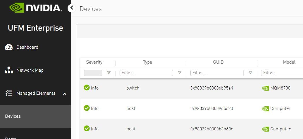
NoteDuring the Introspection phase, the Overcloud InfiniBand devices will appear in the UFM Web UI. Use the time that setup devices are discovered to complete the creation of control PKeys as described in the next step. If Introspection is completed before you are able to set the PKey configuration, and InfiniBand devices are no longer presented in UFM, repeat the Introspection to complete the PKey configuration steps.
The "baremetal" nodes described in this section refer to the nodes which will be deployed as Overcloud Nodes, and not to the Tenant Bare Metal instances which will be created later on.
"--boot-mode bios" is used to deploy Overcloud servers with Legacy BIOS mode. If the nodes are configured with UEFI BIOS, this flag can be omitted
While setup devices are discovered, log into UFM Web UI and configure the control PKeys:
Network Name
PKey ID
Storage
800b
Storage_Mgmt
8015
Internal API
801f
OcProvisioning
8046
Network Name
PKey ID
Storage
800b
Storage_Mgmt
8015
Internal API
801f
OcProvisioning
8046
The procedure includes the following steps:
Verify all setup devices are discovered.
Create PKey with Hex ID.
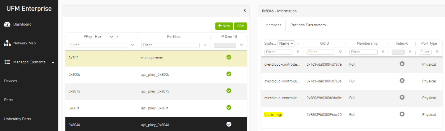
Add the Overcloud nodes (Controller nodes) GUIDs as a member in the control PKey.
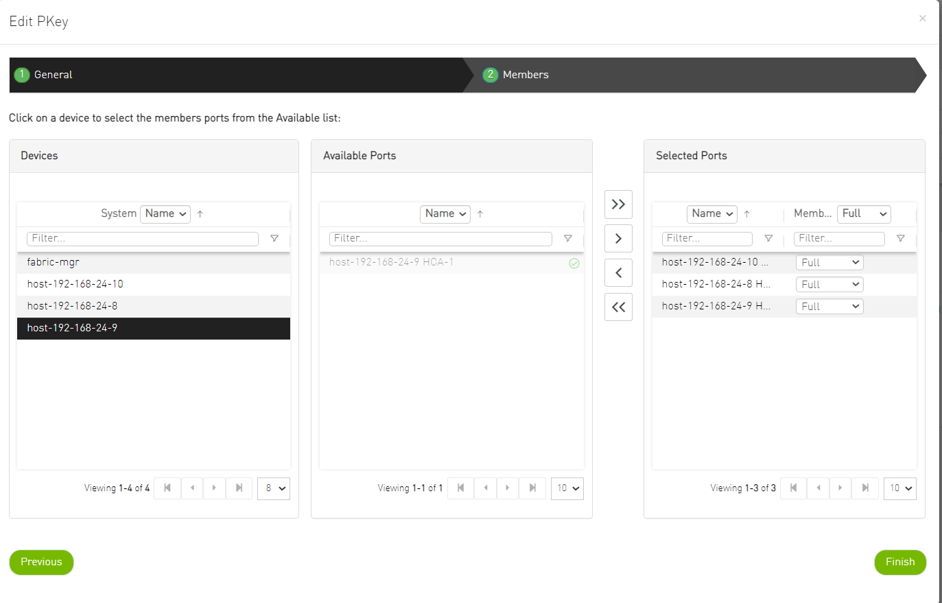
Repeat the steps for every Control PKey.
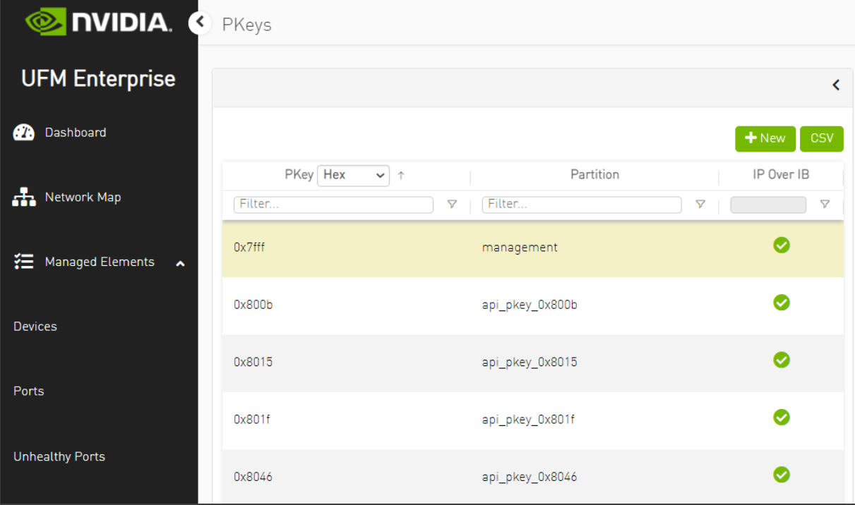
Proceed to the Overcloud Deployment steps below only after all Control PKeys are defined with Controller nodes ports GUID as members.
OpenStack Overcloud Deployment
Download to the Undercloud node and extract the cloud deployment configuration files used for the reference solution in this article: doc-68323870-RDG-Config-Files.zip
Modify the deployment files according to your needs and configuration and place it under the /home/stack/templates/IB directory. The following files were used to deploy the cloud described in this article:
network_data_ib_bm.yaml
vip-data-ib-bm.yaml
roles_data_ib_bm.yaml
containers-prepare-parameter-ib.yaml
node-info-ib-bm.yaml
controller-ib-bm-nics.j2 (referred in node-info-ib-bm.yaml)
neutron-ml2-mlnx-sdn-bm.yaml
NoteThis configuration file contains the connection details of the Fabric Management Node.
Use the UFM API Token collected in previous steps for the MlnxSDNToken parameter.
Use the UFM Node IP on the OpenStack Provisioning network for the MlnxSDNUrl parameter (192.168.24.200)
MlnxSDNUsername and MlnxSDNPassword should be included with empty value
ib-env-bm.yaml
NoteIn this configuration file, the "datacentre" physical network is mapped to the Open vSwitch driver (Ethernet fabric) while "ibnet" physical network is mapped to the IPoIB driver (InfiniBand fabric).
In order to limit the IB-SDN control to the InfiniBand physical network only, explicitly specify the InfiniBand physical network name (for example "physical_networks=ibnet") under the [sdn] section in ml2_conf.ini file on the Controller nodes after the cloud is deployed and restart the neutron_api service container and UFM application.
As "stack" user, issue the deploy command to start Overcloud deployment with the prepared configuration files.
Deploy Command
            $ openstack overcloud deploy --templates /usr/share/openstack-tripleo-heat-templates \
  --networks-file /home/stack/templates/IB/network_data_ib_bm.yaml \
  --vip-file /home/stack/templates/IB/vip-data-ib-bm.yaml \
  --baremetal-deployment /home/stack/templates/IB/node-info-ib-bm.yaml \
  --network-config \
  -r /home/stack/templates/IB/roles_data_ib_bm.yaml \
  -e /home/stack/templates/IB/containers-prepare-parameter-ib.yaml \
  -e /usr/share/openstack-tripleo-heat-templates/environments/podman.yaml \
  -e /usr/share/openstack-tripleo-heat-templates/environments/services/ironic-overcloud.yaml \
  -e /usr/share/openstack-tripleo-heat-templates/environments/services/neutron-ovs.yaml \
  -e /home/stack/templates/IB/neutron-ml2-mlnx-sdn-bm.yaml \
  -e /home/stack/templates/IB/ib-env-bm.yaml \
  --validation-warnings-fatal \
  -e /usr/share/openstack-tripleo-heat-templates/environments/disable-telemetry.yaml
OpenStack Bare Metal Cloud Images Creation
Run the build command below on a CentOS Stream 8 Disk Image Builder machine in order to create a CentOS 8 Stream Guest OS image:
            # export DIB_RELEASE=8-stream
# disk-image-create vm dhcp-all-interfaces cloud-init-datasources cloud-init-config cloud-init-net-conf-disabled rdma-core dracut-regenerate growroot epel centos block-device-efi -o /home/stack/images/centos8-stream
NoteThe command might require setting proper environment variables. For more information regarding image creation and customization procedure refer to: How-to: Create OpenStack Cloud Image with NVIDIA GPU and Network Drivers
The outcome of the command will be a centos8-stream.qcow image file located under /home/stack/images/ directory.
In the example described in this document, the Guest OS image is customized with "cloud-init" element for access credentials, "cloud-init-net-conf-disabled" element for NetworkManager interface auto configuration and "rdma-core" element for rdma-core package installation. Refer to the article above for further information regarding the elements.
The image generated using the specified command is suitable for EFI booting. Make sure to configure the Bare Metal servers with UEFI BIOS mode.
The Undercloud node can be used as a Disk Image Builder (DIB) machine.
For CentOS 7 Guest OS image with IPoIB deployment support, use "mofed" and "dhclient-hw" DIB elements as described in the article: How-to: Create OpenStack Cloud Image with NVIDIA GPU and Network Drivers
Copy the Guest OS image prepared in the previous section to the Undercloud Node and upload it to the Overcloud image store together with the Ironic Deploy images:
            $ source overcloudrc
$ openstack image create centos8-stream-bm-guest --public --disk-format qcow2 --container-format bare --file /home/stack/images/centos8-stream.qcow2
$ openstack image create oc-bm-deploy-kernel --public --disk-format aki --container-format aki --file /home/stack/images/ironic-python-agent.kernel
$ openstack image create oc-bm-deploy-ram --public --disk-format ari --container-format ari --file /home/stack/images/ironic-python-agent.initramfs
$ openstack image list
NoteThe Ironic Deploy kernel and initramfs images are automatically created under /home/stack/images/ directory during OpenStack Undercloud Node Preparation and Installation phase.
For CentOS 7 Deploy Images with IPoIB deployment support, re-build the deploy images with "mofed" and "dhclient-hw" DIB elements as described in the article: How-to: Create OpenStack Cloud Image with NVIDIA GPU and Network Drivers
Bare Metal Nodes Enrollment and Provisioning
On the OpenStack Overcloud, create a provisioning network and subnet that will be used for Bare Metal tenant servers deployment by the Overcloud Controller Ironic service:
NoteMake sure the IP address pool is not colliding with the Oc_provisioning pool as configured in the deployment configuration file network_data.yaml
For the provisioning network vlan, use the same ID you specified for the Controller OcProvisioning network (cloud deployment configuration files) and for the Bare Metal host PXE PKey ID configuration executed by NDO in previous DPU preparation steps (ID "70").
Map the network to the "ibnet" physical network (InfiniBand fabric)
            $ openstack network create provisioning --provider-physical-network ibnet --provider-network-type vlan --provider-segment 70 --share
$ openstack subnet create --network provisioning --subnet-range 172.70.0.0/24 --gateway 172.70.0.1  --allocation-pool start=172.70.0.60,end=172.70.0.99 provisioning-subnet
Once provisioning network is created, the Controllers Nodes ports GUID are added to the PKey as members by the Fabric Management Node. Login to UFM WebUI and manually add as well the Fabric Management Node GUID to this provisioning network PKey.
NoteThis step is required for the Bare Metal PXE over InfiniBand deployment phase
Create a flavor with custom resources for Bare Metal instances:
NoteNotice the CUSTOM_BAREMETAL resource as its name is relevant to next steps
Use physical resources set to "0" as demonstrated below to avoid scheduling based on standard properties for VM instances
            $ openstack flavor create --ram 1024 --disk 20 --vcpus 1 baremetal
$ openstack flavor set baremetal --property resources:CUSTOM_BAREMETAL=1
$ openstack flavor set baremetal --property resources:VCPU=0
$ openstack flavor set baremetal --property resources:MEMORY_MB=0
$ openstack flavor set baremetal --property resources:DISK_GB=0
Collect the GUID of the Bare Metal servers IB Adapter Port connected to the IB fabric . There are several ways to get the InfiniBand Adapter GUID, by looking at the Adapter sticker or by booting the server while its configured for PXE boot and checking its console screen
Prepare a baremetal nodes inventory file named overcloud-nodes-ib-bm-centos8.yaml with the details for the Bare Metal Tenant servers
NoteInclude the host InfiniBand Adapter GUID collected in previous steps for each server as "client-id" parameter with a prefix of "20:<GUID>"
The ports "address" parameter should match the GUID without "03:00"
Update the ipmi credentials per server.
Use a resource class named "baremetal" which corresponds to the CUSTOM_BAREMETAL flavor resource used in previous steps.
Use physical network "ibnet" which is mapped to the InfiniBand fabric.
This deployment yaml should be used for RHEL/CentOS 8 based deployments. For CentOS 7-based deployment use prefix: ff:00:00:00:00:00:02:00:00:02:c9:00:<GUID> as "client-id".
overcloud-nodes-ib-bm-centos8.yaml
            nodes:
    - name: node-1
      driver: ipmi
      network_interface: neutron
      driver_info:
        ipmi_address: "172.16.1.10"
        ipmi_username: "rcon"
        ipmi_password: "******"
      resource_class: baremetal
      properties:
        cpu_arch: x86_64
        local_gb: 400
        memory_mb: '262144'
        cpus: 36
      ports:
        - address: "04:3f:72:9e:0b:a0"
          pxe_enabled: true
          extra:
            client-id: "20:04:3f:72:03:00:9e:0b:a0"
          physical_network: "ibnet"
    - name: node-2
      driver: ipmi
      network_interface: neutron
      driver_info:
        ipmi_address: "172.16.1.20"
        ipmi_username: "rcon"
        ipmi_password: "******"
      resource_class: baremetal
      properties:
        cpu_arch: x86_64
        local_gb: 400
        memory_mb: '262144'
        cpus: 36
      ports:
        - address: "04:3f:72:9e:0b:d0"
          pxe_enabled: true
          extra:
            client-id: "20:04:3f:72:03:00:9e:0b:d0"
          physical_network: "ibnet"
Import the inventory file and verify the nodes are listed:
            $ openstack baremetal create overcloud-nodes-ib-bm-centos8.yaml
$ openstack baremetal node list
Identify the Ironic customized deploy images you uploaded earlier to the image store and set it as the kernel/ramdisk images for the inventory nodes to be used during Bare Metal deployment
            $ DEPLOY_KERNEL=$(openstack image show oc-bm-deploy-kernel -f value -c id)
$ DEPLOY_RAMDISK=$(openstack image show oc-bm-deploy-ram -f value -c id)

$ openstack baremetal node set node-1 --driver-info deploy_kernel=$DEPLOY_KERNEL --driver-info deploy_ramdisk=$DEPLOY_RAMDISK
$ openstack baremetal node set node-2 --driver-info deploy_kernel=$DEPLOY_KERNEL --driver-info deploy_ramdisk=$DEPLOY_RAMDISK
Clean the nodes and prepare it for Bare Metal tenant instance creation
NoteDuring this phase the Bare Metal servers will be booted using ramdisk/kernel images and their local drive will be erased as preparation for the Guest OS deployment phase. The cleaning phase might take a while, you can follow the process over the server console screen.
            $ openstack baremetal node manage node-1 --wait
$ openstack baremetal node manage node-2 --wait
$ openstack baremetal node provide node-1
$ openstack baremetal node provide node-2
Bare Metal Tenant Instance Provisioning
Verify the nodes are "available" for Bare Metal tenant instance deployment using tenant Guest image:
            $ openstack baremetal node list
+--------------------------------------+--------+--------------------------------------+-------------+--------------------+-------------+
| UUID                                 | Name   | Instance UUID                        | Power State | Provisioning State | Maintenance |
+--------------------------------------+--------+--------------------------------------+-------------+--------------------+-------------+
| e5991e0d-78e5-463b-9bf1-e1eb6db2a174 | node-1 | 8891dfec-b7a9-4ddf-82a4-a66f5b05fe9a | power off   | available          | False       |
| 7344efce-d1d1-4736-916d-5c7c30a30f68 | node-2 | 42cc7461-397a-47e4-a849-7c3076cf6eac | power off   | available          | False       |
+--------------------------------------+--------+--------------------------------------+-------------+--------------------+-------------+
Create a tenant network and a subnet
NoteUpon creation of the tenant network Neutron will call UFM to create a tenant PKey matching the specified Vlan ID and add the Controller nodes ports GUID into it.
The vlan ID will be converted into a unique IB PKey (VLAN ID 101 → PKey ID 0x8065 in this case) and will be configured on the fabric by the Fabric Mgmt. Node (UFM) in order to provide tenant isolation.
Map the network to the "ibnet" physical network (InfiniBand fabric).
            $ openstack network create ib_tenant_net --provider-physical-network ibnet --provider-network-type vlan --provider-segment 101 --share
$ openstack subnet create ib_subnet --dhcp --network ib_tenant_net --subnet-range 11.11.11.0/24 --dns-nameserver 8.8.8.8
Spawn Bare Metal tenant instances over the tenant network with the Guest image you uploaded previously to the image store
NoteDuring this phase the Bare Metal servers will be booted twice, one time using ramdisk image and the second time using Guest OS image on the server local drive. You can follow the process over the server console screen.
During the Guest OS deployment phase Neutron will call UFM to add the Bare Metal server port GUID into the newly created tenant Pkey in order to allow the tenant server to fetch an IP from the Controller using DHCP over InfiniBand.
            $ openstack server create --image centos8-stream-bm-guest --flavor baremetal --network ib_tenant_net  centos8_guest1
$ openstack server create --image centos8-stream-bm-guest --flavor baremetal --network ib_tenant_net  centos8_guest2
Verify the Bare Metal tenant instances are up and Active:
            $ openstack baremetal node list
+--------------------------------------+--------+--------------------------------------+-------------+--------------------+-------------+
| UUID                                 | Name   | Instance UUID                        | Power State | Provisioning State | Maintenance |
+--------------------------------------+--------+--------------------------------------+-------------+--------------------+-------------+
| e5991e0d-78e5-463b-9bf1-e1eb6db2a174 | node-1 | 8891dfec-b7a9-4ddf-82a4-a66f5b05fe9a | power on    | active             | False       |
| 7344efce-d1d1-4736-916d-5c7c30a30f68 | node-2 | 42cc7461-397a-47e4-a849-7c3076cf6eac | power on    | active             | False       |
+--------------------------------------+--------+--------------------------------------+-------------+--------------------+-------------+

$ openstack server list
+--------------------------------------+----------------+--------+----------------------------+-------------------------+--------+
| ID                                   | Name           | Status | Networks                   | Image                   | Flavor |
+--------------------------------------+----------------+--------+----------------------------+-------------------------+--------+
| 8891dfec-b7a9-4ddf-82a4-a66f5b05fe9a | centos8_guest1 | ACTIVE | ib_tenant_net=11.11.11.13  | centos8-stream-bm-guest |        |
| 42cc7461-397a-47e4-a849-7c3076cf6eac | centos8_guest2 | ACTIVE | ib_tenant_net=11.11.11.80  | centos8-stream-bm-guest |        |
+--------------------------------------+----------------+--------+----------------------------+-------------------------+--------+
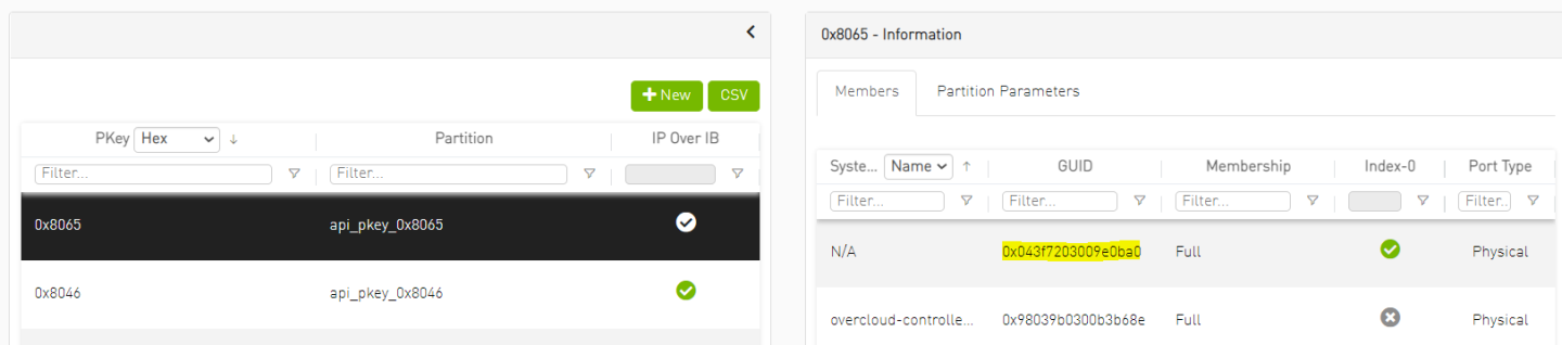
Log into the UFM WebUI and verify a tenant PKey was provisioned automatically per the created tenant network and that relevant GUIDs were added as members.
NoteAs seen below VLAN ID 101 was mapped to PKey ID 0x8065 and the Bare Metal tenant servers port GUID was added to the PKey as member.
External Access to Bare Metal Instance using vRouter and Floating IP
Create an external Ethernet provider network with a gateway leading to the public network.
            $ openstack network create public --provider-physical-network datacentre --provider-network-type flat --external
$ openstack subnet create public_subnet --no-dhcp --network public --subnet-range 10.7.208.0/24 --allocation-pool start=10.7.208.65,end=10.7.208.94 --gateway 10.7.208.1
Create a vRouter and attach to it both the external and the previously created IPoIB tenant networks, in order to allow the Bare Metal instances on the tenant network external connectivity
            $ openstack router create public_router --no-ha
$ openstack router set public_router --external-gateway public
$ openstack router add subnet public_router ib_subnet
Create a Floating IP on the external network and attach it to the Bare Metal instance in order to allow an external access into it
            $ openstack floating ip create --floating-ip-address 10.7.208.99 public
$ openstack server add floating ip centos8_guest1 10.7.208.99
Connect to the Bare Metal tenant instance Floating IP from a machine located on the external network:
[root@external-node]# ssh stack@10.7.208.99
Verify internet connectivity from the instance:
            [stack@host-11-11-11-13 ~]$ sudo su
[root@host-11-11-11-13 stack]# ping google.com
PING google.com (216.58.207.78) 56(84) bytes of data.
64 bytes from fra16s25-in-f14.1e100.net (216.58.207.78): icmp_seq=1 ttl=114 time=57.9 ms
64 bytes from fra16s25-in-f14.1e100.net (216.58.207.78): icmp_seq=2 ttl=114 time=57.8 ms
64 bytes from fra16s25-in-f14.1e100.net (216.58.207.78): icmp_seq=3 ttl=114 time=57.6 ms
^C
--- google.com ping statistics ---
3 packets transmitted, 3 received, 0% packet loss, time 2007ms
rtt min/avg/max/mdev = 57.689/57.845/57.966/0.228 ms
Infrastructure Bandwidth Validation
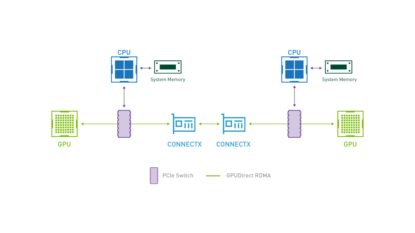
GPUDirect RDMA
GPUDirect RDMA provides direct communication between NVIDIA GPUs in remote systems.
It eliminates the system CPUs and the required buffer copies of data via the system memory, resulting in significant performance boost.
GPUDirect-enabled Bandwidth Test Topology
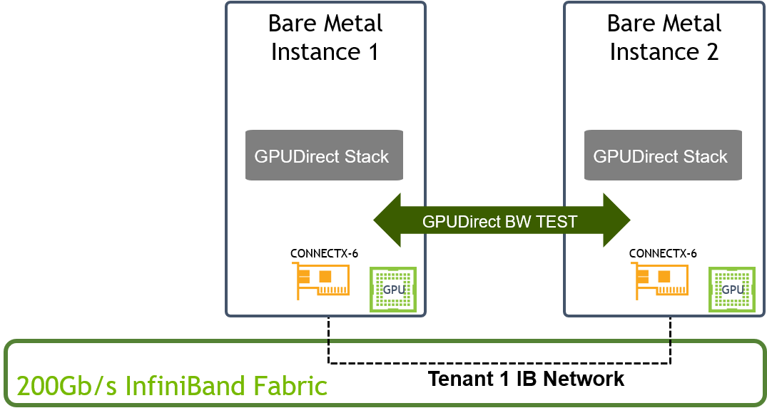
IB_WRITE_BW Test over 200Gb/s InfiniBand Fabric
Some of the configuration applied in this section are not persistent and have to be re-applied after server reboot
Create a custom CentOS 8 Stream Guest OS cloud image with NVIDIA GPU CUDA Drivers, NVIDIA Network Drivers, and GPUDirect benchmark tools as described in this article How-to: Create OpenStack Cloud Image with NVIDIA GPU and Network Drivers The following DIB elements were used to build the image used for this test:
"mofed"
"cuda"
"gpudirect-bench"
Upload the custom guest image and create two Bare Metal tenant instances as instructed in previous sections.
Login to both Bare Metal instances and load nvidia-peermem module:
            # modprobe nvidia-peermem
# lsmod | grep -i peermem
nvidia_peermem         16384  0
nvidia              39047168  3 nvidia_uvm,nvidia_peermem,nvidia_modeset
ib_core               438272  9 rdma_cm,ib_ipoib,nvidia_peermem,iw_cm,ib_umad,rdma_ucm,ib_uverbs,mlx5_ib,ib_cm
Identify the relevant Network/RDMA device to use during the test and notice its NUMA node. For our test it would be ConnectX6 device ib2 / mlx5_4 which is connected to the InfiniBand fabric and located on NUMA node 1.
            # mst start
Starting MST (Mellanox Software Tools) driver set
Loading MST PCI module - Success
[warn] mst_pciconf is already loaded, skipping
Create devices
-W- Missing "lsusb" command, skipping MTUSB devices detection
Unloading MST PCI module (unused) - Success

# ip link show | grep "state UP"
2: eth0: <BROADCAST,MULTICAST,UP,LOWER_UP> mtu 1500 qdisc mq state UP mode DEFAULT group default qlen 1000
10: ib2: <BROADCAST,MULTICAST,UP,LOWER_UP> mtu 1500 qdisc mq state UP mode DEFAULT group default qlen 256


# mst status -v
MST modules:
------------
    MST PCI module is not loaded
    MST PCI configuration module loaded
PCI devices:
------------
DEVICE_TYPE             MST                           PCI       RDMA            NET                       NUMA
ConnectX6DX(rev:0)      /dev/mst/mt4125_pciconf0.1    39:00.1   mlx5_1          net-enp57s0f1             0

ConnectX6DX(rev:0)      /dev/mst/mt4125_pciconf0      39:00.0   mlx5_0          net-enp57s0f0             0

ConnectX6(rev:0)        /dev/mst/mt4123_pciconf1.1    c5:00.1   mlx5_5          net-ib3                   1

ConnectX6(rev:0)        /dev/mst/mt4123_pciconf1      c5:00.0   mlx5_4          net-ib2                   1

ConnectX6(rev:0)        /dev/mst/mt4123_pciconf0.1    3f:00.1   mlx5_3          net-ib1                   0

ConnectX6(rev:0)        /dev/mst/mt4123_pciconf0      3f:00.0   mlx5_2          net-ib0                   0

ConnectX5(rev:0)        /dev/mst/mt4119_pciconf0.1    cb:00.1   mlx5_7          net-enp203s0f1            1

ConnectX5(rev:0)        /dev/mst/mt4119_pciconf0      cb:00.0   mlx5_6          net-enp203s0f0            1
Increase the Adapter maximum accumulated read requests and reboot the server:
NoteUse the relevant MST device ID identified in previous step
The value of 44 max requests we used is a best practice value for 200Gb/s test over a server with PCIe Gen4 CPU as the one we used.
In some cases it is recommended to increase PCIe MaxReadReq size of the network device to 4KB using setpci command in order to further optimize the bandwidth test results
            # mlxconfig -d /dev/mst/mt4123_pciconf1 s  ADVANCED_PCI_SETTINGS=1

Device #1:
----------

Device type:    ConnectX6
Name:           MCX653106A-HDA_Ax
Description:    ConnectX-6 VPI adapter card; HDR IB (200Gb/s) and 200GbE; dual-port QSFP56; PCIe4.0 x16; tall bracket; ROHS R6
Device:         /dev/mst/mt4123_pciconf1

Configurations:                              Next Boot       New
         ADVANCED_PCI_SETTINGS               False(0)        True(1)

 Apply new Configuration? (y/n) [n] : y
Applying... Done!
-I- Please reboot machine to load new configurations.


# mlxconfig -d /dev/mst/mt4123_pciconf1 s  MAX_ACC_OUT_READ=44

Device #1:
----------

Device type:    ConnectX6
Name:           MCX653106A-HDA_Ax
Description:    ConnectX-6 VPI adapter card; HDR IB (200Gb/s) and 200GbE; dual-port QSFP56; PCIe4.0 x16; tall bracket; ROHS R6
Device:         /dev/mst/mt4123_pciconf1

Configurations:                              Next Boot       New
         MAX_ACC_OUT_READ                    0               44

 Apply new Configuration? (y/n) [n] : y
Applying... Done!
-I- Please reboot machine to load new configurations.

#reboot
Identify the relevant GPU devices to use during the test and verify it is - in this case it is would be A100 GPU device. Use the commands below to verify the test devices topology allowing optimized performance bandwidth test:
NoteFor optimized performance test verify Network/RDMA and GPU devices:
Located on the same NUMA node
Connected over PCIe bridges without traversing the PCIe Host Bridge and different NUMA nodes (PIX / PXB topologies)
In the servers we used for this test the Network-RDMA device ( mlx5_4) and GPU device (GPU1 - A100) are sharing NUMA1 and connected over PXB PCIe topology
            # nvidia-smi
Mon Jan 31 06:55:57 2022
+-----------------------------------------------------------------------------+
| NVIDIA-SMI 510.39.01    Driver Version: 510.39.01    CUDA Version: 11.6     |
|-------------------------------+----------------------+----------------------+
| GPU  Name        Persistence-M| Bus-Id        Disp.A | Volatile Uncorr. ECC |
| Fan  Temp  Perf  Pwr:Usage/Cap|         Memory-Usage | GPU-Util  Compute M. |
|                               |                      |               MIG M. |
|===============================+======================+======================|
|   0  Tesla T4            Off  | 00000000:3C:00.0 Off |                    0 |
| N/A   42C    P0    27W /  70W |      0MiB / 15360MiB |      0%      Default |
|                               |                      |                  N/A |
+-------------------------------+----------------------+----------------------+
|   1  NVIDIA A100-PCI...  Off  | 00000000:CC:00.0 Off |                    0 |
| N/A   40C    P0    40W / 250W |      0MiB / 40960MiB |      4%      Default |
|                               |                      |             Disabled |
+-------------------------------+----------------------+----------------------+
+-----------------------------------------------------------------------------+
| Processes:                                                                  |
|  GPU   GI   CI        PID   Type   Process name                  GPU Memory |
|        ID   ID                                                   Usage      |
|=============================================================================|
|  No running processes found                                                 |
+-----------------------------------------------------------------------------+


# nvidia-smi topo -m
        GPU0    GPU1    mlx5_0  mlx5_1  mlx5_2  mlx5_3  mlx5_4  mlx5_5  mlx5_6  mlx5_7  CPU Affinity    NUMA Affinity
GPU0     X      SYS     PXB     PXB     PXB     PXB     SYS     SYS     SYS     SYS     0-23    0
GPU1    SYS      X      SYS     SYS     SYS     SYS     PXB     PXB     PIX     PIX     24-47   1
mlx5_0  PXB     SYS      X      PIX     PXB     PXB     SYS     SYS     SYS     SYS
mlx5_1  PXB     SYS     PIX      X      PXB     PXB     SYS     SYS     SYS     SYS
mlx5_2  PXB     SYS     PXB     PXB      X      PIX     SYS     SYS     SYS     SYS
mlx5_3  PXB     SYS     PXB     PXB     PIX      X      SYS     SYS     SYS     SYS
mlx5_4  SYS     PXB     SYS     SYS     SYS     SYS      X      PIX     PXB     PXB
mlx5_5  SYS     PXB     SYS     SYS     SYS     SYS     PIX      X      PXB     PXB
mlx5_6  SYS     PIX     SYS     SYS     SYS     SYS     PXB     PXB      X      PIX
mlx5_7  SYS     PIX     SYS     SYS     SYS     SYS     PXB     PXB     PIX      X

Legend:

  X    = Self
  SYS  = Connection traversing PCIe as well as the SMP interconnect between NUMA nodes (e.g., QPI/UPI)
  NODE = Connection traversing PCIe as well as the interconnect between PCIe Host Bridges within a NUMA node
  PHB  = Connection traversing PCIe as well as a PCIe Host Bridge (typically the CPU)
  PXB  = Connection traversing multiple PCIe bridges (without traversing the PCIe Host Bridge)
  PIX  = Connection traversing at most a single PCIe bridge
  NV#  = Connection traversing a bonded set of # NVLinks
Enable GPU device persistence mode and lock GPU clock on maximum allowed speed
NoteApply the following settings only when the bandwidth test result is not satisfying
Do NOT set a value higher than allowed per specific GPU device
"nvidia-smi -i <device id> -q -d clock" command can be used to identify the Max Allowed Clock of a device
For the A100 device we used in this test the Max Allowed Clock is 1410 MHz
Use the relevant GPU device ID (-i <device id>) identified in previous step to run the commands below on the required device
            # nvidia-smi -i 1 -pm 1
Enabled persistence mode for GPU 00000000:CC:00.0.
All done.

# nvidia-smi -i 1 -lgc 1410
GPU clocks set to "(gpuClkMin 1410, gpuClkMax 1410)" for GPU 00000000:CC:00.0
All done.
Start GPUDirect ib_write_bw server on one of the instances using the relevant Network/RDMA and GPU devices:
NoteGPU-enabled ib_write_bw is one of the tools installed on the guest image as part of the gpudirect-bench DIB element
It is possible to run RDMA-based test without GPUDirect by omitting the "use_cuda" flag
In some hardware topologies the nvidia-smi GPU device ID does not correlate with the ID used by the perftest tools, as in our case. ib_write_bw output specifies the GPU device that was picked - m ake sure its the required device.
            # ib_write_bw -a --report_gbits -d mlx5_4 -F --use_cuda=0
************************************
* Waiting for client to connect... *
************************************
Start GPUDirect ib_write_bw client on the second instance using the relevant Network and GPU devices and specify the IP of the remote instance:
            # ib_write_bw -a --report_gbits -d mlx5_4 11.11.11.133 -F --use_cuda=0
initializing CUDA
Listing all CUDA devices in system:
CUDA device 0: PCIe address is CC:00
CUDA device 1: PCIe address is 3C:00

Picking device No. 0
[pid = 8136, dev = 0] device name = [NVIDIA A100-PCIE-40GB]
creating CUDA Ctx
making it the current CUDA Ctx
cuMemAlloc() of a 16777216 bytes GPU buffer
allocated GPU buffer address at 00007f80fe000000 pointer=0x7f80fe000000
---------------------------------------------------------------------------------------
                    RDMA_Write BW Test
 Dual-port       : OFF          Device         : mlx5_4
 Number of qps   : 1            Transport type : IB
 Connection type : RC           Using SRQ      : OFF
 PCIe relax order: ON
 ibv_wr* API     : ON
 TX depth        : 128
 CQ Moderation   : 100
 Mtu             : 4096[B]
 Link type       : IB
 Max inline data : 0[B]
 rdma_cm QPs     : OFF
 Data ex. method : Ethernet
---------------------------------------------------------------------------------------
 local address: LID 0x09 QPN 0x0068 PSN 0xabf70a RKey 0x1fcfcd VAddr 0x007f80fe800000
 remote address: LID 0x0a QPN 0x0069 PSN 0xd96335 RKey 0x1fcfcd VAddr 0x007ffab6800000
---------------------------------------------------------------------------------------
 #bytes     #iterations    BW peak[Gb/sec]    BW average[Gb/sec]   MsgRate[Mpps]
 2          5000           0.042454            0.039305            2.456568
 4          5000           0.089589            0.089424            2.794498
 8          5000             0.18               0.18               2.797156
 16         5000             0.36               0.36               2.773971
 32         5000             0.72               0.72               2.795107
 64         5000             1.44               1.43               2.790116
 128        5000             2.88               2.87               2.799646
 256        5000             5.76               5.74               2.805018
 512        5000             11.44              11.44              2.792157
 1024       5000             22.93              22.88              2.793000
 2048       5000             45.83              45.75              2.792391
 4096       5000             92.22              91.94              2.805647
 8192       5000             183.80             183.45             2.799270
 16384      5000             191.43             191.42             1.460421
 32768      5000             195.22             190.73             0.727566
 65536      5000             195.58             195.56             0.373005
 131072     5000             195.48             192.16             0.183256
 262144     5000             195.54             194.38             0.092686
 524288     5000             195.40             193.49             0.046132
 1048576    5000             195.49             193.65             0.023085
 2097152    5000             193.66             193.52             0.011535
 4194304    5000             194.25             193.63             0.005771
 8388608    5000             193.73             193.60             0.002885
---------------------------------------------------------------------------------------
deallocating RX GPU buffer 00007f80fe000000
destroying current CUDA Ctx
NoteThis impressive bandwidth test result is demonstrated using 200Gb/s InfiniBand fabric with GPUDirect support. The servers used for this test support PCIe gen4 and optimized for GPUDirect.
Authors

|
Itai Levy Over the past few years, Itai Levy has worked as a Solutions Architect and member of the NVIDIA Networking “Solutions Labs” team. Itai designs and executes cutting-edge solutions around Cloud Computing, SDN, SDS and Security. His main areas of expertise include NVIDIA BlueField Data Processing Unit (DPU) solutions and accelerated OpenStack/K8s platforms. |