RDG for VMware NSX-V Hardware VTEPs in High-Availability Mode on Spectrum Switches Running Cumulus Linux
Created on Jun 30, 2019
Introduction
This Reference Deployment Guide (RDG) provides instructions on how to integrate Hardware VTEPs with VMware NSX-V in OVSDB Server High-Availability Mode on Cumulus Linux.
This guide assumes the following software and drivers are installed:
VMware ESXi 6.7 Update 1
vCenter 6.7 Update 1
VMware NSX Data Center for vSphere version 6.4.4
Cumulus Linux version 3.7.2. OVSDB server HA mode is in early access on this Cumulus Linux release.
References
Overview
NVIDIA Spectrum ® switches running Cumulus Linux OS supports integration with VMware NSX Data Center in both standalone and OVSDB server high availability.
For OVSDB server high availability mode (active-active data-plane), two switches must have MLAG configuration and act as an MLAG cluster.
The MLAG peers contain OVSDB server and vtepd configuration.
The OVSDB servers synchronize their databases and always maintain the replicated state unless any failover occurs.
Both of the vtepd components communicate with the active OVSDB server to read the configuration and then push it to the kernel.
Only the active OVSDB server communicates with the NSX controller unless a failover occurs and then the standby OVSDB server takes over automatically.
Although the Cumulus switches are configured as an MLAG pair, the NSX controller sees them as a single system (the NSX controller is not aware that multiple switches exist).
Hardware and Software Requirements
1. ESXi server platform with an adapter card based on ConnectX®-4/5 HCA devices.
2. 4 leaf and 2 spine switches based on NVIDIA Scale-Out SN2000 Ethernet Switch Series.
3. VMware vSphere 6.7 u1 cluster installed and configured.
4. VMware vCenter 6.7 u1 installed and configured.
5. VMware NSX Data Center for vSphere version 6.4.4 installed and configured.
6. Installer Privileges: The installation requires administrator privileges on the target machine.
Logical Design
In this guide, we will cover two use cases:
Each Ubuntu physical server is able to connect the VM in the same VLAN-VNI on the other side.
Each Ubuntu physical server is able to connect the VM in different VLAN-VNI on the other side.
For that purpose, NSX Edge will be implemented. It will allow the hosts from different subnets (VLANs/VNIs) to communicate.

Setup Overview
Before you start, make sure you are familiar with VMware vSphere, vCenter, NSX Data Center and Cumulus Linux deployment and management procedures.
This guide does not contain step-by-step instructions for performing all of the required standard vSphere, vCenter and NSX-V installation and configuration tasks because they often depend on customer requirements.

Equipment
In this guide, we are using the following hardware specification.

Network Connectivity

Prerequisites
Network Configuration
MLAG Configuration
Before the OVSDB HA configuration, we need to make sure that both pairs of leaf switches are running an MLAG configuration. In this document, Leaf Switch 3 and Leaf Switch 4 (connected to the ESXi servers) are also running MLAG for HA.
Make sure both Ubuntu physical servers have a bond interface in active-active mode (lacp mode 4).
To configure MLAG, run the following commands.
On Leaf1,2:
Leaf1
            net add bond clag-1 bond slaves swp1
net add bond clag-2 bond slaves swp2
net add bond peerlink bond slaves swp55,swp56
net add bond clag-1 clag id 1
net add bond clag-2 clag id 2
net add interface peerlink.4094 clag backup-ip 192.168.1.16
net add interface peerlink.4094 clag peer-ip 169.254.1.2
net add interface peerlink.4094 clag priority 1000
net add interface peerlink.4094 clag sys-mac 44:38:39:FF:01:01
net add interface peerlink.4094 ip address 169.254.1.1/24
net commit
Leaf2
            net add bond clag-1 bond slaves swp1
net add bond clag-2 bond slaves swp2
net add bond peerlink bond slaves swp55,swp56
net add bond clag-1 clag id 1
net add bond clag-2 clag id 2
net add interface peerlink.4094 clag backup-ip 192.168.1.7
net add interface peerlink.4094 clag peer-ip 169.254.1.1
net add interface peerlink.4094 clag priority 2000
net add interface peerlink.4094 clag sys-mac 44:38:39:FF:01:01
net add interface peerlink.4094 ip address 169.254.1.2/24
net commit
Verify MLAG status on both MLAG pairs:
Leaf1
net show clag
Leaf1 Output
            The peer is alive
     Our Priority, ID, and Role: 1000 7c:fe:90:ff:5a:5c primary
    Peer Priority, ID, and Role: 2000 7c:fe:90:ff:23:dc secondary
          Peer Interface and IP: peerlink.4094 169.254.1.2
               VxLAN Anycast IP: 1.1.1.10
                      Backup IP: 192.168.1.16 (active)
                     System MAC: 44:38:39:ff:01:01

CLAG Interfaces
Our Interface      Peer Interface     CLAG Id  Conflicts              Proto-Down Reason
----------------   ----------------   -------  --------------------  -----------------
          clag-1   clag-1             1         -                      -
          clag-2   clag-2             2         -                      -
Leaf2
net show clag
Leaf2 Output
            The peer is alive
     Our Priority, ID, and Role: 1000 7c:fe:90:ff:5a:5c primary
    Peer Priority, ID, and Role: 2000 7c:fe:90:ff:23:dc secondary
          Peer Interface and IP: peerlink.4094 169.254.1.1
               VxLAN Anycast IP: 1.1.1.10
                      Backup IP: 192.168.1.7 (active)
                     System MAC: 44:38:39:ff:01:01

CLAG Interfaces
Our Interface      Peer Interface     CLAG Id  Conflicts              Proto-Down Reason
----------------   ----------------   -------  --------------------  -----------------
          clag-1   clag-1             1         -                      -
          clag-2   clag-2             2         -                      -
On Leaf3,4.
Leaf3
            net add bond clag-1 bond slaves swp1
net add bond clag-2 bond slaves swp2
net add bond clag-3 bond slaves swp3
net add bond clag-1 clag id 1
net add bond clag-2 clag id 2
net add bond clag-3 clag id 3
net add interface peerlink.4094 clag backup-ip 192.168.1.37
net add interface peerlink.4094 clag peer-ip 169.254.1.2
net add interface peerlink.4094 clag priority 1000
net add interface peerlink.4094 clag sys-mac 44:38:39:FF:02:02
net add interface peerlink.4094 ip address 169.254.1.1/30
net commit
Leaf4
            net add bond clag-1 bond slaves swp1
net add bond clag-2 bond slaves swp2
net add bond clag-3 bond slaves swp3
net add bond clag-1 clag id 1
net add bond clag-2 clag id 2
net add bond clag-3 clag id 3
net add interface peerlink.4094 clag backup-ip 192.168.1.18
net add interface peerlink.4094 clag peer-ip 169.254.1.1
net add interface peerlink.4094 clag priority 2000
net add interface peerlink.4094 clag sys-mac 44:38:39:FF:02:02
net add interface peerlink.4094 ip address 169.254.1.2/30
net commit
Verify MLAG status on both MLAG pairs:
Leaf3
net show clag
Leaf3 Output
            The peer is alive
     Our Priority, ID, and Role: 1000 7c:fe:90:fb:80:dc primary
    Peer Priority, ID, and Role: 2000 7c:fe:90:28:cd:dc secondary
          Peer Interface and IP: peerlink.4094 169.254.1.2
                      Backup IP: 192.168.1.37 (active)
                     System MAC: 44:38:39:ff:02:02

CLAG Interfaces
Our Interface      Peer Interface     CLAG Id  Conflicts              Proto-Down Reason
----------------   ----------------   -------  --------------------  -----------------
          clag-1   clag-1             1         -                      -
          clag-2   clag-2             2         -                      -
          clag-3   clag-3             3         -                      -
Leaf4
net show clag
Leaf4 Output
            The peer is alive
     Our Priority, ID, and Role: 1000 7c:fe:90:fb:80:dc primary
    Peer Priority, ID, and Role: 2000 7c:fe:90:28:cd:dc secondary
          Peer Interface and IP: peerlink.4094 169.254.1.1
                      Backup IP: 192.168.1.37 (active)
                     System MAC: 44:38:39:ff:02:02

CLAG Interfaces
Our Interface      Peer Interface     CLAG Id  Conflicts              Proto-Down Reason
----------------   ----------------   -------  --------------------  -----------------
          clag-1   clag-1             1         -                      -
          clag-2   clag-2             2         -                      -
          clag-3   clag-3             3         -                      -
On Leaf Switch 1 and Leaf Switch 2 there are loopback interfaces with MLAG anycast-ip (on top) for VXLAN tunnel usage.
On Leaf Switch 3 and Leaf Switch 4 there is IP-virtual address (VRR) of MLAG for VTEPs reachability on the ESXi hosts (VLAN 130 chosen for this purpose).
BGP Underlay Routing Configuration
Configure BGP underlay network reachability between all leaf and spine switches.
The connectivity should be between the MLAG anycast-ip to the VTEPs on the ESXi machines.
Leaf1
            net add loopback lo ip address 1.1.1.1/32
net add loopback lo clag vxlan-anycast-ip 1.1.1.10
net add bgp autonomous-system 65001
net add bgp neighbor swp49 interface remote-as external
net add bgp neighbor swp50 interface remote-as external
net add bgp neighbor swp51 interface remote-as external
net add bgp neighbor swp52 interface remote-as external
net add bgp ipv4 unicast network 1.1.1.1/32
net add bgp ipv4 unicast network 1.1.1.10/32
net commit
Leaf2
            net add loopback lo ip address 1.1.1.2/32
net add loopback lo clag vxlan-anycast-ip 1.1.1.10
net add bgp autonomous-system 65002
net add bgp neighbor swp49 interface remote-as external
net add bgp neighbor swp50 interface remote-as external
net add bgp neighbor swp51 interface remote-as external
net add bgp neighbor swp52 interface remote-as external
net add bgp ipv4 unicast network 1.1.1.2/32
net add bgp ipv4 unicast network 1.1.1.10/32
net commit
Spine1
            net add bgp autonomous-system 65005
net add bgp neighbor swp1 interface remote-as external
net add bgp neighbor swp2 interface remote-as external
net add bgp neighbor swp3 interface remote-as external
net add bgp neighbor swp4 interface remote-as external
net add bgp neighbor swp5 interface remote-as external
net add bgp neighbor swp6 interface remote-as external
net add bgp neighbor swp7 interface remote-as external
net add bgp neighbor swp8 interface remote-as external
net commit
Spine2
            net add bgp autonomous-system 65005
net add bgp neighbor swp1 interface remote-as external
net add bgp neighbor swp2 interface remote-as external
net add bgp neighbor swp3 interface remote-as external
net add bgp neighbor swp4 interface remote-as external
net add bgp neighbor swp5 interface remote-as external
net add bgp neighbor swp6 interface remote-as external
net add bgp neighbor swp7 interface remote-as external
net add bgp neighbor swp8 interface remote-as external
net commit
Leaf3
            net add vlan 130 ip address 192.168.130.252/24
net add vlan 130 ip address-virtual 00:00:5E:00:01:01 192.168.130.1/24
net add vlan 130 vlan-id 130
net add bridge bridge pvid 130
net add bgp autonomous-system 65003
net add bgp neighbor swp49 interface remote-as external
net add bgp neighbor swp50 interface remote-as external
net add bgp neighbor swp51 interface remote-as external
net add bgp neighbor swp52 interface remote-as external
net add bgp ipv4 unicast network 192.168.130.0/24
net commit
Leaf4
            net add vlan 130 ip address 192.168.130.253/24
net add vlan 130 ip address-virtual 00:00:5E:00:01:01 192.168.130.1/24
net add vlan 130 vlan-id 130
net add bridge bridge pvid 130
net add bgp autonomous-system 65004
net add bgp neighbor swp49 interface remote-as external
net add bgp neighbor swp50 interface remote-as external
net add bgp neighbor swp51 interface remote-as external
net add bgp neighbor swp52 interface remote-as external
net add bgp ipv4 unicast network 192.168.130.0/24
net commit
Verify the BGP state and underlay routing:
Leaf1
net show bgp summary
Leaf1 Output
            show bgp ipv4 unicast summary
=============================
BGP router identifier 1.1.1.10, local AS number 65001 vrf-id 0
BGP table version 9
RIB entries 7, using 1064 bytes of memory
Peers 4, using 77 KiB of memory

Neighbor          V         AS MsgRcvd MsgSent   TblVer InQ OutQ  Up/Down State/PfxRcd
swx-vwd-06(swp49) 4      65005  25496   25500        0   0    0  21:14:13            3
swx-vwd-06(swp50) 4      65005  25496   25500        0   0    0  21:14:13            3
swx-vwd-05(swp51) 4      65005  25497   25503        0   0    0  21:14:13            3
swx-vwd-05(swp52) 4      65005  25497   25503        0   0    0  21:14:13            3
Leaf1
net show route
Leaf1 Output
            show ip route
=============
Codes: K - kernel route, C - connected, S - static, R - RIP,
       O - OSPF, I - IS-IS, B - BGP, E - EIGRP, N - NHRP,
	   T - Table, v - VNC, V - VNC-Direct, A - Babel, D - SHARP,
       F - PBR,
       > - selected route, * - FIB route
K>* 0.0.0.0/0 [0/0] via 192.168.1.21, eth0, 21:18:16
C>* 1.1.1.1/32 is directly connected, lo, 21:18:16
B>* 1.1.1.2/32 [20/0] via fe80::268a:7ff:fe05:2ff4, swp51, 21:18:00
  *                   via fe80::268a:7ff:fe05:2ff6, swp52, 21:18:00
  *                   via fe80::7efe:90ff:fe58:e0f6, swp50, 21:18:00
  *                   via fe80::7efe:90ff:fe58:e0f4, swp49, 21:18:00
C>* 1.1.1.10/32 is directly connected, lo, 21:18:04
C>* 169.254.1.0/24 is directly connected, peerlink.4094, 21:18:08
C>* 169.254.1.3/32 is directly connected, peerlink.4094, 21:18:08
C>* 192.168.1.0/24 is directly connected, eth0, 21:18:16
B>* 192.168.130.0/24 [20/0] via fe80::268a:7ff:fe05:2ff4, swp51, 21:18:00
  *                         via fe80::268a:7ff:fe05:2ff6, swp52, 21:18:00
  *                         via fe80::7efe:90ff:fe58:e0f6, swp50, 21:18:00
  *                         via fe80::7efe:90ff:fe58:e0f4, swp49, 21:18:00
Leaf2
net show bgp summary
Leaf2 Output
            show bgp ipv4 unicast summary
=============================
BGP router identifier 1.1.1.10, local AS number 65002 vrf-id 0
BGP table version 17
RIB entries 7, using 1064 bytes of memory
Peers 4, using 77 KiB of memory
Neighbor          V         AS MsgRcvd MsgSent   TblVer InQ OutQ  Up/Down State/PfxRcd
swx-vwd-06(swp49) 4      65005  25659   25659        0    0    0 21:21:52            3
swx-vwd-06(swp50) 4      65005  25659   25659        0    0    0 21:21:52            3
swx-vwd-05(swp51) 4      65005  25660   25660        0    0    0 21:21:52            3
swx-vwd-05(swp52) 4      65005  25665   25672        0    0    0 21:21:50            3
Leaf2
net show route
Leaf2 Output
            show ip route
=============
Codes: K - kernel route, C - connected, S - static, R - RIP,
       O - OSPF, I - IS-IS, B - BGP, E - EIGRP, N - NHRP,
       T - Table, v - VNC, V - VNC-Direct, A - Babel, D - SHARP,
       F - PBR,
       > - selected route, * - FIB route

K>* 0.0.0.0/0 [0/0] via 192.168.1.21, eth0, 21:26:00
B>* 1.1.1.1/32 [20/0] via fe80::268a:7ff:fe05:2ff0, swp51, 21:18:34
  *                   via fe80::268a:7ff:fe05:2ff2, swp52, 21:18:34
  *                   via fe80::7efe:90ff:fe58:e0f2, swp50, 21:18:34
  *                   via fe80::7efe:90ff:fe58:e0f0, swp49, 21:18:34
C>* 1.1.1.2/32 is directly connected, lo, 21:26:00
C>* 1.1.1.10/32 is directly connected, lo, 21:25:45
C>* 169.254.1.0/24 is directly connected, peerlink.4094, 21:18:42
C>* 192.168.1.0/24 is directly connected, eth0, 21:26:00
B>* 192.168.130.0/24 [20/0] via fe80::268a:7ff:fe05:2ff0, swp51, 21:25:40
  *                         via fe80::268a:7ff:fe05:2ff2, swp52, 21:25:40
  *                         via fe80::7efe:90ff:fe58:e0f2, swp50, 21:25:40
  *                         via fe80::7efe:90ff:fe58:e0f0, swp49, 21:25:40
Leaf3
net show bgp summary
Leaf3 Output
            show bgp ipv4 unicast summary
=============================
BGP router identifier 192.168.130.252, local AS number 65003 vrf-id 0
BGP table version 321
RIB entries 7, using 1064 bytes of memory
Peers 4, using 77 KiB of memory

Neighbor          V        AS MsgRcvd MsgSent   TblVer InQ OutQ  Up/Down State/PfxRcd
swx-vwd-06(swp49) 4      65005 493504  493491        0   0    0 6d21h17m            3
swx-vwd-06(swp50) 4      65005 493536  493526        0   0    0 6d21h17m            3
swx-vwd-05(swp51) 4      65005 493537  493527        0   0    0 6d21h17m            3
swx-vwd-05(swp52) 4      65005 493535  493527        0   0    0 6d21h17m            3
Leaf3
net show route
Leaf3 Output
            show ip route
=============
Codes: K - kernel route, C - connected, S - static, R - RIP,
       O - OSPF, I - IS-IS, B - BGP, E - EIGRP, N - NHRP,
       T - Table, v - VNC, V - VNC-Direct, A - Babel, D - SHARP,
       F - PBR,
       > - selected route, * - FIB route


K>* 0.0.0.0/0 [0/0] via 192.168.1.21, eth0, 01w3d21h
B>* 1.1.1.1/32 [20/0] via fe80::268a:7ff:fe05:2ff8, swp51, 21:19:03
  *                   via fe80::7efe:90ff:fe58:e0fa, swp50, 21:19:03
  *                   via fe80::268a:7ff:fe05:2ffa, swp52, 21:19:03
  *                   via fe80::7efe:90ff:fe58:e0f8, swp49, 21:19:03
B>* 1.1.1.2/32 [20/0] via fe80::268a:7ff:fe05:2ff8, swp51, 21:26:11
  *                   via fe80::7efe:90ff:fe58:e0fa, swp50, 21:26:11
  *                   via fe80::268a:7ff:fe05:2ffa, swp52, 21:26:11
  *                   via fe80::7efe:90ff:fe58:e0f8, swp49, 21:26:11
B>* 1.1.1.10/32 [20/0] via fe80::268a:7ff:fe05:2ff8, swp51, 21:25:33
  *                    via fe80::7efe:90ff:fe58:e0fa, swp50, 21:25:33
  *                    via fe80::268a:7ff:fe05:2ffa, swp52, 21:25:33
  *                    via fe80::7efe:90ff:fe58:e0f8, swp49, 21:25:33
C>* 169.254.1.0/30 is directly connected, peerlink.4094, 03:43:03
C>* 192.168.1.0/24 is directly connected, eth0, 01w3d21h
C * 192.168.130.0/24 is directly connected, vlan130-v0, 6d21h19m
C>* 192.168.130.0/24 is directly connected, vlan130, 6d21h19m
Leaf4
net show bgp summary
Leaf4 Output
             show bgp ipv4 unicast summary
=============================
BGP router identifier 192.168.130.253, local AS number 65004 vrf-id 0
BGP table version 5
RIB entries 7, using 1064 bytes of memory
Peers 4, using 77 KiB of memory

Neighbor          V         AS MsgRcvd MsgSent   TblVer InQ OutQ  Up/Down State/PfxRcd
swx-vwd-06(swp49) 4      65005   4425    4427        0    0    0 03:40:52            3
swx-vwd-06(swp50) 4      65005   4423    4425        0    0    0 03:40:52            3
swx-vwd-05(swp51) 4      65005   4423    4425        0    0    0 03:40:52            3
swx-vwd-05(swp52) 4      65005   4423    4425        0    0    0 03:40:52            3
Leaf4
net show route
Leaf4 Output
             show ip route
=============
Codes: K - kernel route, C - connected, S - static, R - RIP,
       O - OSPF, I - IS-IS, B - BGP, E - EIGRP, N - NHRP,
       T - Table, v - VNC, V - VNC-Direct, A - Babel, D - SHARP,
       F - PBR,
       > - selected route, * - FIB route

K>* 0.0.0.0/0 [0/0] via 192.168.1.21, eth0, 03:43:27
B>* 1.1.1.1/32 [20/0] via fe80::268a:7ff:fe05:2ffc, swp51, 03:43:24
  *                   via fe80::268a:7ff:fe05:2ffe, swp52, 03:43:24
  *                   via fe80::7efe:90ff:fe58:e0fc, swp49, 03:43:24
  *                   via fe80::7efe:90ff:fe58:e0fe, swp50, 03:43:24
B>* 1.1.1.2/32 [20/0] via fe80::268a:7ff:fe05:2ffc, swp51, 03:43:24
  *                   via fe80::268a:7ff:fe05:2ffe, swp52, 03:43:24
  *                   via fe80::7efe:90ff:fe58:e0fc, swp49, 03:43:24
  *                   via fe80::7efe:90ff:fe58:e0fe, swp50, 03:43:24
B>* 1.1.1.10/32 [20/0] via fe80::268a:7ff:fe05:2ffc, swp51, 03:43:24
  *                    via fe80::268a:7ff:fe05:2ffe, swp52, 03:43:24
  *                    via fe80::7efe:90ff:fe58:e0fc, swp49, 03:43:24
  *                    via fe80::7efe:90ff:fe58:e0fe, swp50, 03:43:24
C>* 169.254.1.0/30 is directly connected, peerlink.4094, 03:43:26
C>* 192.168.1.0/24 is directly connected, eth0, 03:43:27
C * 192.168.130.0/24 is directly connected, vlan130-v0, 03:43:22
C>* 192.168.130.0/24 is directly connected, vlan130, 03:43:22
Connectivity from MLAG anycast-ip (Leaf Switches 1 and 2) to VLAN130 (Leaf Switches 3 and 4):
Leaf2
ping 192.168.130.253 -I 1.1.1.10
Leaf2 Output
            PING 192.168.130.253 (192.168.130.253) from 1.1.1.10 : 56(84) bytes of data.
64 bytes from 192.168.130.253: icmp_seq=1 ttl=63 time=0.191 ms
64 bytes from 192.168.130.253: icmp_seq=2 ttl=63 time=0.212 ms
64 bytes from 192.168.130.253: icmp_seq=3 ttl=63 time=0.259 ms
Leaf2
ping 192.168.130.252 -I 1.1.1.10
Leaf2 Output
            PING 192.168.130.252 (192.168.130.252) from 1.1.1.10 : 56(84) bytes of data.
64 bytes from 192.168.130.252: icmp_seq=1 ttl=63 time=0.226 ms
64 bytes from 192.168.130.252: icmp_seq=2 ttl=63 time=0.267 ms
64 bytes from 192.168.130.252: icmp_seq=3 ttl=63 time=0.265 ms
vSphere and NSX Configuration
Virtual Distributed Switch (VDS) Configuration
Make sure that you have a VDS with all necessary configuration in your environment Port Groups.
NSX Manager and Controllers Configuration
After underlay network reachability is verified, make sure that you have an NSX Manager and 3 NSX controllers.
All of them should be on the same subnet as the management network of the switches (in this case it’s 192.168.1.x/24).


ESXi Hosts Preparation
Make sure that all ESXi hosts are prepared and each one has VTEP with the IP addresses in 192.168.130.0/24 subnet - 192.168.130.51/52/53.

LACP Configuration on vSphere Side
As we saw earlier, all ESXi machines are connected in active-active (LACP) LAG to Leaf Switch 3 and Leaf Switch 4 (clag-1/2/3).
Create LACP LAG on the VDS, later all ESXi and virtual switches will use this LAG to connect to active-active mode to the physical switches.
For creating LACP LAG, go into Networking category in vSphere web client.

Select the VDS, and go to Configure tab.

In our lab we prepared a VDS.
Select LACP and press + to add a new LAG. In the pop-up window, type LAG’s Name, Number of ports, Mode and Load balancing mode.

Once the LAG created, run the Migrating network traffic to LAGs wizard to assign the relevant NICs to it. From this wizard it is possible to go over all the elements needed.

Click the 3th step – Manage Distributed Port Groups, select Teaming and failover and click Next.

Click Select distributed port groups:

Select the needed port groups (Mgmt DVS, storage and vMotion VDS) and click OK.

When all are selected, go to the next step by clicking Next.

Use the arrows to move lag1 to be the Active uplink and other Uplinks to be Unused.

When a LAG is selected as the only active uplink, the load balancing mode of the LAG overrides the load balancing mode of the port group.
Click Next and Finish.
Go to the wizard again and click the 2nd step Add and Manage Hosts.

Click the Manage host networking task and then Next.

Press on +Attached hosts.

Select the ESXi machines that need to connect to the LAG and click OK.

After hosts attached click Next.

Select Manage physical adapters, Migrate virtual machine networking checkboxes and click Next.

VMs can be migrated into the logical switches by selecting Migrate virtual machine networking. Otherwise, they can be added when the logical switch is created (covered later in the document).
Select the physical adapters that you wish to map into the LAG and click Assign uplink.

In the pop-up window, select the LAG port (lag1-0) for the 1st physical vmnic and click OK.

Add the 2nd vmnic to the 2nd LAG port exactly like the first one. Now both ports are assigned to the LAG.

Repeat the steps above to add all vmnics of the other ESXi machines to the LAG. Once all added, click Next.

On Analyze VM networking click Next.
Migrate the VMs into the logical switches by selecting the needed VM and clicking Assign port groups.

Select the logical switch (for VM01 – LogicalSwitch1 and for VM02 – LogicalSwitch2) and click OK.

When both VMs are attached to the relevant network (logical switch – VNI), click Next and then Finish.
OVSDB Server HA Configuration on Cumulus Linux and HW-VTEPs on ESXi Hypervisor
OVSDB Server Configuration on Cumulus Linux
Prior to configuring the HW-VTEP gateway, the logical switches, and ports that comprise the VXLAN, openvswitch-vtep service must be enabled and started.
Enable and start the openvswitch-vtep service on Leaf Switch 1 and Leaf Switch 2.
Leaf1
            sudo systemctl enable openvswitch-vtep.service
sudo systemctl start openvswitch-vtep.service
Leaf2
            sudo systemctl enable openvswitch-vtep.service
sudo systemctl start openvswitch-vtep.service
Run the OVSDB server configuration script on both the MLAG primary and secondary switches.
On the switch that will act as ACTIVE OVSDB server run the following script.
Laef1
sudo vtep-bootstrap --db_ha active --db_ha_vip 169.254.1.3:9998 --db_ha_repl_sv 169.254.1.1:9999 --controller_ip 192.168.1.221 vtep1 1.1.1.10 192.168.1.7
Leaf1 Output
             Executed:
    create certificate on a switch, to be used for authentication with controller
     ().
Executed:
    sign certificate
     (vtep1-req.pem     Sun Feb 17 12:17:16 UTC 2019
        fingerprint 61eca4c99853a5d22cce65e7f4a8a903a2aefcae).
Executed:
    define physical switch
     ().
Executed:
    define NSX controller IP address in OVSDB
     ().
Executed:
    define local tunnel IP address on the switch
     ().
Executed:
    define management IP address on the switch
     ().
Executed:
    restart a service
     ().
Script usage:
db_ha active specifies that the OVSDB server on this switch is the active server
db_ha_vip is any unused IP address in the peerlink subnet (4094 is typically used). This creates a /32 route that can be reached from either MLAG switch (169.254.1.3:9998 in the example below).
db_ha_repl_sv specifies the IP address of the active OVSDB server (169.254.1.1:9999 in the example below). The standby OVSDB server uses this IP address to synchronize the database.
controller_ip is the IP address of the NSX controller (192.168.1.221 in the example below)
The ID for the VTEP (vtep1 in the example below)
The datapath IP address of the VTEP – VXLAN anycast-ip (1.1.1.10 in the example below)
The management IP address of the switch (192.168.1.7 in the example below). This interface is used for control traffic.
On the switch that will act as STANDBY OVSDB server, run exactly the same “vtep-bootstrap” command with the same options as on the ACTIVE OVSDB server but replace “db_ha active” with “db_ha standby”.
Leaf2
sudo vtep-bootstrap --db_ha standby --db_ha_vip 169.254.1.3:9998 --db_ha_repl_sv 169.254.1.1:9999 --controller_ip 192.168.1.221 vtep1 1.1.1.10 192.168.1.7
Leaf2 Output
            Executed:
    create certificate on a switch, to be used for authentication with controller
     ().
Executed:
    sign certificate
     (vtep1-req.pem     Sun Feb 17 12:18:00 UTC 2019
        fingerprint a4cda030fe5e458c0d7ba44e22f52650f01bcd75).
Executed:
    define physical switch
     ().
Executed:
    define NSX controller IP address in OVSDB
     ().
Executed:
    define local tunnel IP address on the switch
     ().
Executed:
    define management IP address on the switch
     ().
Executed:
    restart a service
     ().
Once the service script is executed, certificate files will be created: hostname-cert.pem and hostname-privkey.pem.
Copy the certificate files from the active OVSDB server to the same location on the standby OVSDB server.
Leaf1
            sudo scp /home/cumulus/vtep1-cert.pem cumulus@192.168.1.16:/home/cumulus
sudo scp /home/cumulus/vtep1- privkey.pem.pem cumulus@192.168.1.16:/home/cumulus
To complete the OVSDB server configuration, run the following commands on both active and standby OVSDB servers (both MLAG switches).
Leaf1
            sudo systemctl restart openvswitch-vtep.service
sudo ifreload -a
sudo systemctl restart networking.service
Leaf2
            sudo systemctl restart openvswitch-vtep.service
sudo ifreload -a
sudo systemctl restart networking.service
HW-VTEP Configuration on ESXi Hypervisor
Configure the switch as a VTEP Gateway (Hardware VTEP).
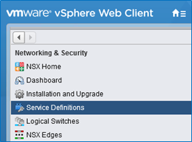
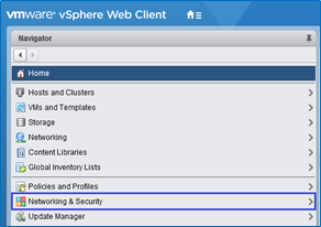
Go to vSphere Web Client into Networking and Security and click Service Definitions category.

Select Hardware Devices tab. To add the switch press +.

In the pop-up window, type HW-VTEP name and insert the Certificate created on the active OVSDB server.
Copy the certificate from the switch (make sure to copy from BEGIN CERTIFICATE to END CERTIFICATE).
Leaf1
cat /home/cumulus/vtep1-cert.pem
Leaf1 Output
            -----BEGIN CERTIFICATE-----
MIIDgTCCAmkCAQQwDQYJKoZIhvcNAQENBQAwgYExCzAJBgNVBAYTAlVTMQswCQYD
VQQIDAJDQTEVMBMGA1UECgwMT3BlbiB2U3dpdGNoMREwDwYDVQQLDAhzd2l0Y2hj
YTE7MDkGA1UEAwwyT1ZTIHN3aXRjaGNhIENBIENlcnRpZmljYXRlICgyMDE5IEZl
YiAyNCAxMjo1NzoxOCkwHhcNMTkwMjI0MTI1NzMyWhcNMjkwMjIxMTI1NzMyWjCB
ijELMAkGA1UEBhMCVVMxCzAJBgNVBAgMAkNBMRUwEwYDVQQKDAxPcGVuIHZTd2l0
Y2gxHzAdBgNVBAsMFk9wZW4gdlN3aXRjaCBjZXJ0aWZpZXIxNjA0BgNVBAMMLXZ0
ZXAxIGlkOmFlNDkxOGMyLWIyMDEtNDdjNC1hMjg2LWI2ZDkxNzVlNzA1ZDCCASIw
DQYJKoZIhvcNAQEBBQADggEPADCCAQoCggEBAL+NdEigSQDhBgHD1miisgCQ6P2S
zuW3FeZljMbumwUaaTyVFBo19UYvAP6GoPuHVrGXDyHzegWuJ5zrng5FtMDy8z3G
kAK6X8j+SqLYAKIbRPjpxunC86bKO4Ke6qp7j3Y+/dPanShqKGrxew67XLzMWaz4
7SJhSUtFDFM8xqxhqekUAFDGNDGEcHeyifqXC5I8B5SR6osd4k3efjJLv4LfvCmQ
1Fd2Jb/yJjFHZLvUTl/QDCrxdwmv1wxH7/AtJBSGq7B72YBnBKopSEZgU2U5ioiv
WomJeL2jJO8BTKrsOov3mx01KJsUWLpX2jn52m21nPBCxY2pL4L2yV12L/cCAwEA
ATANBgkqhkiG9w0BAQ0FAAOCAQEAic0JpSs7hedybPBA654mnklAxJKygWQ51d26
qVUgx0UQJXl3DsUYit2Jtx9gvxyIPptuMdpAL+UIxfdMsUJ0X306WcAkfyYlSR7W
UW8m63ihuYv5Jb0nw5ljqS1Fwp9QsiIi/c0/Ly1+QL6mFw3rsR6NwZw7GDK2J4/n
NfRLA6ORSzs3IQh8A71YyAGs1EVFfWHmKCDmiS8yB1zs5TIxhecEvpWvyvJgVDcr
lXaWpyi+r6vMd9kYGBuvCyW2V5+yreI6EaemIEcUyUfbJz5rTomQw2dO8WS3y472
fYQ0PGV+eN7hqubIejnYmGb7a4OHrDOyybOvsBrs4wb0Lr2KmQ==
-----END CERTIFICATE-----
Make sure to enable BFD service and click OK.

The active OVSDB server is now added as Hardware VTEP.
Configuration Verification
On ESXi Hypervisor, check the Connectivity and the BFD.

Connectivity will show UP and BFD ✓ if HW-VTEP added successfully.
On Leaf Switch 1 and Leaf Switch 2, verify that the OVSDB active and standby servers configured successfully.
The state of the active OVSDB server should be “active”.
Leaf1
            sudo ovs-appctl -t /var/run/openvswitch/ovsdb-server.`pidof ovsdb-server`.ctl ovsdb-server/sync-status
state: active
The state of the standby OVSDB server should be “backup”.
Leaf2
            sudo ovs-appctl -t /var/run/openvswitch/ovsdb-server.`pidof ovsdb-server`.ctl ovsdb-server/sync-status
state: backup
replicating: tcp:169.254.1.1:9999
database: hardware_vtep
The active OVSDB server is the only one that is connected to the NSX controllers. In case of failure, the standby OVSDB server will connect to the controllers.
Check active OVSDB server for connectivity to the NSX controllers.
Leaf1
sudo ovsdb-client dump Manager
Leaf1 Output
            Manager table
_uuid     inactivity_probe is_connected max_backoff other_config status     target
--------  ---------------- ------------ ----------- ------------ ---------- -----------
6415dc62… []               true         []          {}           {sec_since_connect="4", state=ACTIVE} "ssl:192.168.1.220:6640"
88a3012a… []               true         []          {}           {sec_since_connect="4", state=ACTIVE} "ssl:192.168.1.221:6640"
4f547754… []               true         []          {}           {sec_since_connect="4", state=ACTIVE} "ssl:192.168.1.222:6640"
Make sure that the BFD sessions between the VTEPs are UP and active.
Leaf1
sudo ptmctl -b
Leaf1 Output
            --------------------------------------------------------------
port   peer            state  local     type       diag  vrf
--------------------------------------------------------------
vxln0  192.168.130.52  Up     1.1.1.10  singlehop  N/A   N/A
vxln0  192.168.130.53  Up     1.1.1.10  singlehop  N/A   N/A
vxln0  192.168.130.51  Up     1.1.1.10  singlehop  N/A   N/A
When the switchd and networking services are restarted, the BFD sessions might be interrupted. If you notice that the sessions are down, restart the openvswitch-vtep.service.
Transport Zone and Logical Network Configuration
To configure the Transport Layer, go to vSphere Web Client into Networking and Security tab and click the Installation and Upgrade category.


Click on Logical Network Settings, configure VXLAN Port and Segment IDs (VNIs).

Click Edit on VXLAN Port, type 4789 and SAVE.

Click Edit on the Segment IDs (VNIs), type 5000-5999 and SAVE.

Go to Transport Zones tab and click +ADD.

Type transport zone name, select Unicast for VXLAN control plane handling by NSX Controller Cluster and select the ESXi Cluster. To finish click ADD.

Now the replication cluster needs to be configured, go back to Service Definitions category.

Go to Hardware Devices tab and Edit the Replication Cluster Nodes.

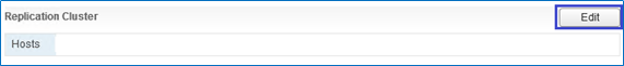
In the pop-up window, from the available objects, select the replication nodes (ESXi Hypervisors) and move them right using the arrow, then click OK.

These Hypervisors are now connected to the NSX controllers for BUM traffic replication between the VTEPs.

Layer 2 Traffic over VXLAN Tunnels (L2 Stretch)
For building connectivity between hosts, the logical layer must be configured. It requires the definition of logical switches (VXLAN instances) and the logical ports on them.
The configuration below is in reference to the following setup diagram.

Servers/VMs are connected as follows:
VM01 (orange) and Ubuntu (orange) – VLAN1634 (VNI5000)
IP addresses: VM01 – 192.168.34.101/24, Ubuntu – 192.168.34.204/24
VM02 (aqua) and Ubuntu (aqua) – VLAN1635 (VNI5001)
IP addresses: VM02 – 192.168.35.102/24, Ubuntu – 192.168.35.205/24
On Leaf1 and 2, Ubuntu orange is connected to MLAG port clag-1 and Ubuntu aqua to clag-2.
On Leaf3 and 4, ESXi machines connected to MLAG ports clag-1,clag-2.
Each VLAN will be mapped to the appropriate VNI. For that, two logical switches need to be created, one for VNI5000 and another for VNI5001.
Logical Switch Configuration
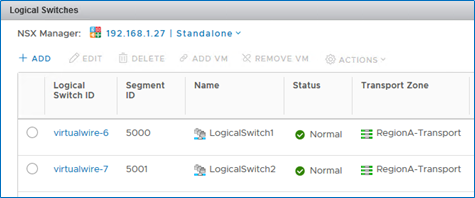
To configure the logical switches, go to the Logical Switches category and click +ADD.

In the pop-up window, type the logical switch’s name “LogicalSwitch1”, select transport zone, Unicast replication mode and enable IP Discovery. When done, click ADD.

New logical switch “LogicalSwitch1” is added successfully and the first Segment ID (VNI) is set to it (VNI 5000).

For the second VNI (5001) a new logical switch needs to be created — “LogicalSwitch2”. Once created, it will take the next Segment ID (VNI) automatically. To create it, follow exactly the same steps for “LogicalSwitch1” creation.
Now, both logical switches should be displayed.
Logical switchports need to be defined on the logical switches. This binds the VLAN-to-VNI for each switch port.
For that, go to the Logical Switches category, select the logical switch, click ACTIONS and select Manage Hardware Bindings.


Click +ADD to add a new port binding line, then Select the switch port/s to bind to the HW VTEP.
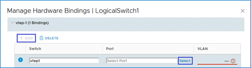
In the pop-up window, select the switch port (clag-1 connected to Ubuntu-blue) to bind and click OK.

Add a VLAN to the switch port binding (VLAN1634).

To bind the port connected to the second Ubuntu server (VLAN1635), perform the same steps as with LogicalSwitch1.
Select LogicalSwitch2, ACTIONS and Manage Hardware Bindings.

Click +ADD again to add a new line, then select the needed port (clag-2) and choose its VLAN (VLAN1635).

Now, there is a hardware port binding to each of the logical switches.

Connect the VMs located on the ESXi machines to the same logical switches, each VM in the appropriate logical switch. To add a VMs to a logical switch, select the switch and click ADD VM.

Select the VM (VM01) from Available Objects and click the arrow. Once it moved to the Selected Objects, click NEXT.

Select the vNIC of the VM and click NEXT and then FINISH.

Repeat the same steps to add VM02 the LogicalSwitch2. Once added, there will be VMs connected to the logical switches.

Add the logical switches to the LAG (lag1) that was created before. Go to Networking, choose the Logical Switch, click the Configure tab and edit to Policies settings.


In the pop-up window, go to Teaming and failover category and change the Failover order. Use the arrows to move the lag1 interface as Active uplink and the regular ports to Unused uplinks.

If logical switches are already created, it is possible to the LAG by selecting them in the migrating network traffic to LAG wizard presented earlier in this document.
Configuration Verification
After all is configured, we get a VXLAN L2 stretch on VLAN1634 and VLAN1635.
Leaf switches 1 and 2 have VXLAN 5000 and 5001 interfaces in MLAG:
Leaf1
net show clag
Leaf1 Output
            The peer is alive
	 Our Priority, ID, and Role: 1000 7c:fe:90:ff:5a:5c primary
	Peer Priority, ID, and Role: 2000 7c:fe:90:ff:23:dc secondary
		  Peer Interface and IP: peerlink.4094 169.254.1.2
			   VxLAN Anycast IP: 1.1.1.10
					  Backup IP: 192.168.1.16 (active)
					 System MAC: 44:38:39:ff:01:01


CLAG Interfaces
Our Interface      Peer Interface     CLAG Id  Conflicts              Proto-Down Reason
----------------   ----------------   -------  --------------------   -----------------
          clag-1   clag-1             1         -                      -
          clag-2   clag-2             2         -                      -
           vxln0   vxln0              -         -                      -
        vxln5001   vxln5001           -         -                      -
        vxln5000   vxln5000           -         -                      -
Leaf2
net show clag
Leaf2 Output
            The peer is alive
	 Our Priority, ID, and Role: 1000 7c:fe:90:ff:5a:5c primary
	Peer Priority, ID, and Role: 2000 7c:fe:90:ff:23:dc secondary
		  Peer Interface and IP: peerlink.4094 169.254.1.1
			   VxLAN Anycast IP: 1.1.1.10
					  Backup IP: 192.168.1.7 (active)
					 System MAC: 44:38:39:ff:01:01

CLAG Interfaces
Our Interface      Peer Interface     CLAG Id  Conflicts              Proto-Down Reason
----------------   ----------------   -------  --------------------   -----------------
          clag-1   clag-1             1         -                      -
          clag-2   clag-2             2         -                      -
           vxln0   vxln0              -         -                      -
        vxln5001   vxln5001           -         -                      -
        vxln5000   vxln5000           -         -                      -
Check VLANs and VXLAN interfaces created on leaf1 and leaf2 by the NSX controller (should be identical).
Leaf1
net show bridge vlan
Leaf1 Output
            Interface  VLAN  	 Flags                  VNI
---------  --------- ---------------------  ----
clag-1     1634
clag-2     1635
dummy-vx   1634-1635
peerlink   1         PVID, Egress Untagged
           1634-1635
vxln5000   1634       PVID, Egress Untagged  5000
vxln5001   1635       PVID, Egress Untagged  5001
Leaf2
net show bridge vlan
Leaf2 Output
            Interface  VLAN  	 Flags                  VNI
---------  --------- ---------------------  ----
clag-1     1634
clag-2     1635
dummy-vx   1634-1635
peerlink   1         PVID, Egress Untagged
           1634-1635
vxln5000   1634       PVID, Egress Untagged  5000
vxln5001   1635       PVID, Egress Untagged  5001
Leaf switches 1 and 2 should have the MAC addresses of the remote VMs located on the ESXi machines. All of them pushed by the NSX controller from the appropriate VXLAN interfaces.
Leaf1
net show bridge macs
Leaf1 Output
            VLAN      Master   Interface  MAC                TunnelDest      State     Flags  LastSeen
--------  -------- ---------  -----------------  --------------  --------- -----  --------
1634      br-vxlan dummy-vx   00:23:20:00:00:01                  static            19:04:59
1634      br-vxlan vxln5000   00:50:56:bc:d0:9a                  static            19:04:24
1635      br-vxlan dummy-vx   00:23:20:00:00:01                  static            19:04:59
1635      br-vxlan vxln5001   00:50:56:bc:c5:5a                  static            19:04:24
untagged            vxln5000   00:00:00:00:00:00  192.168.130.53  permanent self   19:04:33
untagged            vxln5000   00:50:56:bc:d0:9a  192.168.130.51  static    self   19:05:03
untagged            vxln5001   00:00:00:00:00:00  192.168.130.53  permanent self   19:04:33
untagged            vxln5001   00:50:56:bc:c5:5a  192.168.130.51  static    self   19:05:03
untagged  br-vxlan clag-1     7c:fe:90:ff:5a:7c                  permanent         19:05:05
untagged  br-vxlan clag-2     7c:fe:90:ff:5a:7d                  permanent         19:05:05
untagged  br-vxlan dummy-vx   00:23:20:00:00:01                  permanent         19:05:00
untagged  br-vxlan peerlink   7c:fe:90:ff:5a:5c                  permanent         19:05:05
untagged  br-vxlan vxln5000   32:09:e4:02:d9:16                  permanent         19:05:05
untagged  br-vxlan vxln5001   e2:4f:07:a4:5a:59                  permanent         19:05:05
untagged  br-vxln0 dummy0     00:23:20:00:00:01                  permanent         19:04:20
untagged  br-vxln0 vxln0      aa:64:05:d7:28:11                  permanent         19:04:20
Leaf2
net show bridge macs
Leaf2 Output
            VLAN      Master   Interface  MAC                TunnelDest      State     Flags  LastSeen
--------  -------- ---------  -----------------  --------------  --------- -----  --------
1634      br-vxlan clag-1     7c:fe:90:12:20:38                                    00:02:55
1634      br-vxlan dummy-vx   00:23:20:00:00:01                  static            19:07:49
1634      br-vxlan vxln5000   00:50:56:bc:d0:9a                  static            19:07:48
1635      br-vxlan dummy-vx   00:23:20:00:00:01                  static            19:07:49
1635      br-vxlan vxln5001   00:50:56:bc:c5:5a                  static            19:07:48
untagged            vxln5000   00:00:00:00:00:00  192.168.130.53  permanent self   19:07:52
untagged            vxln5000   00:50:56:bc:d0:9a  192.168.130.51  static    self   19:07:51
untagged            vxln5001   00:00:00:00:00:00  192.168.130.53  permanent self   19:07:52
untagged            vxln5001   00:50:56:bc:c5:5a  192.168.130.51  static    self   19:07:51
untagged  br-vxlan clag-1     7c:fe:90:ff:23:fc                  permanent         19:07:51
untagged  br-vxlan clag-2     7c:fe:90:ff:23:fd                  permanent         19:07:52
untagged  br-vxlan dummy-vx   00:23:20:00:00:01                  permanent         19:07:50
untagged  br-vxlan peerlink   7c:fe:90:ff:23:dc                  permanent         19:07:52
untagged  br-vxlan vxln5000   5e:ce:c1:03:eb:1e                  permanent         19:07:52
untagged  br-vxlan vxln5001   16:74:ec:00:ca:62                  permanent         19:07:52
untagged  br-vxln0 dummy0     00:23:20:00:00:01                  permanent         19:07:50
untagged  br-vxln0 vxln0      3e:6d:8b:22:5a:10                  permanent         19:07:50
Check connectivity between Ubuntu servers to the VMs in the same VNI (L2 stretch):
Connectivity from Ubuntu-orange to VM01 (from 192.168.34.204 to 192.168.34.101).
            root@clx-vwd-204~# ping 192.168.34.101 -I 192.168.34.204
PING 192.168.34.101 (192.168.34.101) from 192.168.34.204 : 56(84) bytes of data.
64 bytes from 192.168.34.101: icmp_seq=1 ttl=64 time=0.552 ms
64 bytes from 192.168.34.101: icmp_seq=2 ttl=64 time=0.544 ms
64 bytes from 192.168.34.101: icmp_seq=3 ttl=64 time=0.406 ms
Connectivity from Ubuntu-azure to VM02 (from 192.168.35.205 to 192.168.35.102).
            root@clx-vwd-205~# ping 192.168.35.102 -I 192.168.35.205
PING 192.168.35.102 (192.168.35.102) from 192.168.35.205 : 56(84) bytes of data.
64 bytes from 192.168.35.102: icmp_seq=1 ttl=64 time=0.495 ms
64 bytes from 192.168.35.102: icmp_seq=2 ttl=64 time=0.535 ms
64 bytes from 192.168.35.102: icmp_seq=3 ttl=64 time=0.624 ms
Layer 3 Traffic Over VXLAN Tunnels (VXLAN Centralized Routing)
As we configured before, each Ubuntu server was able to connect the VM in the same VLAN-VNI on the other side.
If there is a need to communicate between the different VLANs, VXLAN routing must be enabled. For that purpose, NSX Edge will be implemented. It will allow hosts from different subnets (VLANs/VNIs) to communicate.
The routing is centralized, which means that the routing is done by a specific logical switch (NSX Edge) located on the ESX hypervisor which acts as the default gateway for all hosts in a particular subnet.
When Ubuntu from VLAN1634 needs to communicate with hosts in VLAN1635, the traffic will need to get the default gateway (NSX Edge) located on the ESX, then the routing decision will be made by it and the traffic will be routed to a different VNI.

NSX Edge Configuration
To create routing between the VLANs (VNIs), L3 VNI needs to be crated.
Add new a Logical Switch that will be used for L3 VNI. The creation process is the same as the previously added logical switches. Next VNI will be added to it automatically.


New logical switch created with VNI5002.

To create and configure NSX Edge. Go to NSX Edge category and click +.

In the pop-up window, select Edge Services Gateway, type Edge’s name, Hostname, check to Deploy NSX Edge checkbox and click Next (High-Availability can be checked if HA mode is desired).

Set NSX Edge CLI User Name, Password, and check the Enable SSH checkbox and click Next.

The password should match the following conditions

Configure desired Appliance Size and location (by clicking +).

Select the Cluster, Database and click OK.

Now NSX Edge resource pool created, click Next.

To configure NSX Edge interfaces by clicking +.

In the pop-up window, sent vNIC Name (NSX interface vNIC), Internal Type and connect to the Edge-HA logical switch by clicking Select and selecting Edge-HA.


Set interface Primary IP Address and Subnet Prefix Length (you can use a subnet of /30) and click OK.

After the NSX Edge interface created, click “Next”.
Skip the NSX Edge Default Gateway settings and continue to the next section by clicking Next.
To configure Firewall and HA. Set the firewall to Accept all, select the vNIC Edge-HA and configure Management IPs for NSX Edge HA (as mentioned, it’s optional to select HA).

Now, the NSX Edge is created, click Finish to deploy it.

NSX Edge is now created and deployed (in HA mode with two Edge VMs).

Now, the logical switches of VNI5000 and 5001 need to be added to the NSX Edge and VLANs default gateway addresses should be set.
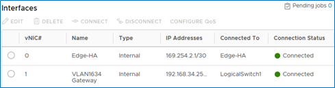
Double click the created NSX Edge and go to the Interfaces section.

Select vnic1 and click EDIT.

In the pop-up window, type vNIC name (“VLAN1634 Gateway”), select Internal Type, connect to “LogicalSwitch1” (of VNI5000), set VLANs Default Gateway address by pressing +ADD. Once finished, click SAVE.

Now, VLAN1634 (VNI5000) has a default gateway for routing.
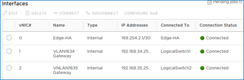
Select vNic 2 and add the LogicalSwitch2 for VLAN1635 (VNI5001) gateway. Follow the same steps as for vNIC 1.
Configuration Verification
When both Gateways are created, we have routing between the blue and the azure subnets (VNI5000 and VNI5001):
Connectivity from Ubuntu-blue to VM02 (from 192.168.34.204 to 192.168.35.102).
Ubuntu-blue Console
            root@clx-vwd-204~# ping 192.168.35.102 -I 192.168.34.204
PING 192.168.35.102 (192.168.35.102) from 192.168.34.204 : 56(84) bytes of data.
64 bytes from 192.168.35.102: icmp_seq=1 ttl=64 time=2.68 ms
64 bytes from 192.168.35.102: icmp_seq=2 ttl=64 time=1.19 ms
64 bytes from 192.168.35.102: icmp_seq=3 ttl=64 time=1.26 ms
Connectivity from Ubuntu-azure to VM01 (from 192.168.35.205 to 192.168.34.101).
Ubuntu-azure Console
            root@clx-vwd-204~# ping 192.168.34.101 -I 192.168.35.205
PING 192.168.34.101 (192.168.34.101) from 192.168.34.204 : 56(84) bytes of data.
64 bytes from 192.168.34.101: icmp_seq=1 ttl=64 time=4.27 ms
64 bytes from 192.168.34.101: icmp_seq=2 ttl=64 time=1.27 ms
64 bytes from 192.168.34.101: icmp_seq=3 ttl=64 time=1.34 ms
Leaf Switches 1 and 2 have now the Edges (HA) MAC addresses from both VNI5000 and 5001.
Leaf1
net show bridge macs
Leaf1 Output
            VLAN      Master   Interface  MAC                TunnelDest      State     Flags  LastSeen
--------  -------- ---------  -----------------  --------------  --------- -----  --------
1634      br-vxlan clag-1     7c:fe:90:12:20:38                                    00:01:38
1634      br-vxlan dummy-vx   00:23:20:00:00:01                  static            19:47:20
1634      br-vxlan vxln5000   00:50:56:bc:2e:33                  static            00:05:44
1634      br-vxlan vxln5000   00:50:56:bc:53:17                  static            00:05:43
1634      br-vxlan vxln5000   00:50:56:bc:d0:9a                  static            19:46:45
1635      br-vxlan clag-2     24:8a:07:38:22:10                                    00:00:37
1635      br-vxlan dummy-vx   00:23:20:00:00:01                  static            19:47:20
1635      br-vxlan vxln5001   00:50:56:bc:2c:39                  static            00:03:29
1635      br-vxlan vxln5001   00:50:56:bc:9f:32                  static            00:03:30
1635      br-vxlan vxln5001   00:50:56:bc:c5:5a                  static            19:46:45
untagged            vxln5000   00:00:00:00:00:00  192.168.130.53  permanent self   19:46:54
untagged            vxln5000   00:50:56:bc:2e:33  192.168.130.53  static    self   00:05:44
untagged            vxln5000   00:50:56:bc:53:17  192.168.130.51  static    self   00:05:43
untagged            vxln5000   00:50:56:bc:d0:9a  192.168.130.51  static    self   19:47:24
untagged            vxln5001   00:00:00:00:00:00  192.168.130.53  permanent self   19:46:54
untagged            vxln5001   00:50:56:bc:2c:39  192.168.130.51  static    self   00:03:29
untagged            vxln5001   00:50:56:bc:9f:32  192.168.130.53  static    self   00:03:30
untagged            vxln5001   00:50:56:bc:c5:5a  192.168.130.51  static    self   19:47:24
untagged  br-vxlan  clag-1     7c:fe:90:ff:5a:7c                  permanent        19:47:25
untagged  br-vxlan  clag-2     7c:fe:90:ff:5a:7d                  permanent        19:47:26
untagged  br-vxlan  dummy-vx   00:23:20:00:00:01                  permanent        19:47:21
untagged  br-vxlan  peerlink   7c:fe:90:ff:5a:5c                  permanent        19:47:26
untagged  br-vxlan  vxln5000   32:09:e4:02:d9:16                  permanent        19:47:26
untagged  br-vxlan  vxln5001   e2:4f:07:a4:5a:59                  permanent        19:47:26
untagged  br-vxln0  dummy0     00:23:20:00:00:01                  permanent        19:46:41
untagged  br-vxln0  vxln0      aa:64:05:d7:28:11                  permanent        19:46:41
Leaf1
net show bridge macs
Leaf2 Output
            VLAN      Master   Interface  MAC                TunnelDest      State     Flags  LastSeen
--------  -------- ---------  -----------------  --------------  --------- -----  --------
1634      br-vxlan clag-1     7c:fe:90:12:20:38                                    00:04:02
1634      br-vxlan dummy-vx   00:23:20:00:00:01                  static            19:49:05
1634      br-vxlan vxln5000   00:50:56:bc:2e:33                  static            00:08:07
1634      br-vxlan vxln5000   00:50:56:bc:53:17                  static            00:08:07
1634      br-vxlan vxln5000   00:50:56:bc:d0:9a                  static            19:49:03
1635      br-vxlan clag-2     24:8a:07:38:22:10                                    00:03:11
1635      br-vxlan dummy-vx   00:23:20:00:00:01                  static            19:49:05
1635      br-vxlan vxln5001   00:50:56:bc:2c:39                  static            00:05:52
1635      br-vxlan vxln5001   00:50:56:bc:9f:32                  static            00:05:53
1635      br-vxlan vxln5001   00:50:56:bc:c5:5a                  static            19:49:03
untagged           vxln5000   00:00:00:00:00:00  192.168.130.53  permanent  self   19:49:07
untagged           vxln5000   00:50:56:bc:2e:33  192.168.130.53  static     self   00:08:07
untagged           vxln5000   00:50:56:bc:53:17  192.168.130.51  static     self   00:08:07
untagged           vxln5000   00:50:56:bc:d0:9a  192.168.130.51  static     self   19:49:06
untagged           vxln5001   00:00:00:00:00:00  192.168.130.53  permanent  self   19:49:07
untagged           vxln5001   00:50:56:bc:2c:39  192.168.130.51  static     self   00:05:52
untagged           vxln5001   00:50:56:bc:9f:32  192.168.130.53  static     self   00:05:53
untagged           vxln5001   00:50:56:bc:c5:5a  192.168.130.51  static     self   19:49:06
untagged  br-vxlan clag-1     7c:fe:90:ff:23:fc                  permanent         19:49:07
untagged  br-vxlan clag-2     7c:fe:90:ff:23:fd                  permanent         19:49:07
untagged  br-vxlan dummy-vx   00:23:20:00:00:01                  permanent         19:49:05
untagged  br-vxlan peerlink   7c:fe:90:ff:23:dc                  permanent         19:49:07
untagged  br-vxlan vxln5000   5e:ce:c1:03:eb:1e                  permanent         19:49:07
untagged  br-vxlan vxln5001   16:74:ec:00:ca:62                  permanent         19:49:07
untagged  br-vxln0 dummy0     00:23:20:00:00:01                  permanent         19:49:05
untagged  br-vxln0 vxln0      3e:6d:8b:22:5a:10                  permanent         19:49:06
Failure Scenario
In normal situation Leaf Switch 1 is active OVSDB and Leaf Switch 2 is standby OVSDB server.

If the active OVSDB server fails (Leaf Switch 1), standby OVSDB server (Leaf Switch 2) will connect to the NSX controllers automatically and switch its role to ACTIVE OVSDB server (till the original active server is back again).

When Leaf Switch 1 fails, Leaf Switch 2 displays.
Leaf2
            sudo ovs-appctl -t
/var/run/openvswitch/ovsdb-server.`pidof ovsdb-server`.ctl
ovsdb-server/sync-status
state: active
Leaf2
sudo ovsdb-client dump Manager
Leaf2 Output
            Manager table
_uuid     inactivity_probe is_connected max_backoff other_config status     							target
--------  ---------------- ------------ ----------- ------------ ---------- 							-----------
6415dc62… []               true         []          {}           {sec_since_connect="9",state=ACTIVE} 	"ssl:192.168.1.220:6640"
88a3012a… []               true         []          {}           {sec_since_connect="9",state=ACTIVE} 	"ssl:192.168.1.221:6640"
4f547754… []               true         []          {}           {sec_since_connect="9",state=ACTIVE} 	"ssl:192.168.1.222:6640"
Leaf2
sudo ptmctl -b
Leaf2 Output
            --------------------------------------------------------------
port   peer            state  local    type       diag  vrf
--------------------------------------------------------------
vxln0  192.168.130.52  Up    1.1.1.10  singlehop  N/A   N/A
vxln0  192.168.130.53  Up    1.1.1.10  singlehop  N/A   N/A
vxln0  192.168.130.51  Up    1.1.1.10  singlehop  N/A   N/A
Once the active OVSDB server is up again (Leaf Switch 1), the standby server (Leaf Switch 2) will be disconnected from the NSX controllers and sync from the active OVSDB server again.
Leaf Switch 1 will be active again with the connection to the NSX Controllers (with BFD).
Leaf Switch 2 new state.
Leaf2
sudo ovs-appctl -t /var/run/openvswitch/ovsdb-server.`pidof ovsdb-server`.ctl ovsdb-server/sync-status
Leaf2 Output
            state: backup
replicating: tcp:169.254.1.1:9999
database: hardware_vtep
Leaf2
sudo ovsdb-client dump Manager
Leaf2 Output
            Manager table
_uuid inactivity_probe     is_connected max_backoff  other_config status                                                             target
-------------------------- --------     ------------ -----------  ------------------------------------------------------------------ ------------------------------------
4f547754… []               true         []           {}           {sec_since_connect="56", sec_since_disconnect="58",state=ACTIVE}   "ssl:192.168.1.222:6640"
6415dc62… []               true         []           {}           {sec_since_connect="56", sec_since_disconnect="58",state=IDLE}     "ssl:192.168.1.220:6640"
88a3012a… []               true         []           {}           {sec_since_connect="56", sec_since_disconnect="58",state=IDLE}     "ssl:192.168.1.221:6640"
Leaf2
            sudo ptmctl -b
ERR: No BFD sessions . Check connections
Done!
Authors
|

|
Boris Kovalev Boris Kovalev has worked for the past several years as a Solutions Architect, focusing on NVIDIA Networking/Mellanox technology, and is responsible for complex machine learning, Big Data and advanced VMware-based cloud research and design. Boris previously spent more than 20 years as a senior consultant and solutions architect at multiple companies, most recently at VMware. He has written multiple reference designs covering VMware, machine learning, Kubernetes, and container solutions which are available at the Mellanox Documents website. |