RDG for vSphere Distributed Services Engine (Project Monterey) deployment over NVIDIA BlueField-2 DPU
Created on Jul 01,2023
Scope
The following R eference D eployment G uide ( RDG ) explains how to install and configure VMware vSphere 8.0b Distributed Services Engine (DSE) with VMware NSX 4.1 version on a single vSphere cluster over Dell NVIDIA® BlueField Data Processing Units (DPU) and end-to-end NVIDIA 25Gbps Ethernet solution. This setup is capable of running all types of workloads included DPDK-based applications. VMware’s vSAN Express Storage Architecture (ESA) will be used as a share storage for the environment.
Abbreviations and Acronyms
|
Term |
Definition |
Term |
Definition |
|
DAC |
Direct Attached Cable |
MFT |
NVIDIA Mellanox Firmware Tools |
|
DCUI |
Direct Console User Interface |
NOS |
Network Operation System |
|
DHCP |
Dynamic Host Configuration Protocol |
OOB |
Out-of-band |
|
DPDK |
Data Plane Development Kit |
OSA |
Original Storage Architecture |
|
DPU |
Data Processing Unit |
RDG |
R eference D eployment G uide |
|
DSE |
Distributed Services Engine |
SR-IOV |
Single Root Input/Output Virtualization |
|
EDP |
Enhanced Data Path |
VF |
Virtual Function |
|
ESA |
Express Storage Architecture |
VM |
Virtual Machine |
Introduction
Contemporary applications are being built using a microservices architecture, where individual services are deployed on servers spread throughout the datacenter. Although this approach has numerous advantages, it also results in an increase in network traffic and places a significant burden on network communications. Tasks associated with traffic routing, network overlays (for Geneve or VXLAN), security (such as a distributed firewall), telemetry, storage, and remote management can consume more than 30% of CPU resources on each virtualized server. This, in turn, can affect the availability of server CPU resources for running end-user workloads.
One way to resolve this inefficiency is to offload network and security services to a DPU (Data Processing Unit) that contains purpose-built engines for accelerating these services. In 2022, VMware launched VMware vSphere® Distributed Services Engine™(previously known as “Project Monterey”) which allows vSphere 8 to offload and accelerate NSX network and security services to a DPU such as NVIDIA BlueField-2. This offload frees up host CPU cores to run end-user workloads while accelerating these services on NVIDIA BlueField-2 engines allows for high performance network, security, and storage services.
Starting with vSphere 8, VMware and NVIDIA introduce a VMware vSphere Distributed Switch and VMware NSX networking running on the NVIDIA BlueField-2 DPU.
The NVIDIA BlueField-2 DPU provides a new control point for scaling infrastructure functions and enables security controls that are separate from the workload domain.
This guide provides step-by-step instructions to deploy and configure VMware ESXi and NVIDIA BlueField-2 DPU, vCenter, and NSX manager to support a DSE environment on a single vSphere cluster including technology overview, design, component selection, and deployment steps.
References
Solution Architecture
Key Components and Technologies
NVIDIA Spectrum Ethernet Switches
Flexible form-factors with 16 to 128 physical ports, supporting 1GbE through 400GbE speeds.
Based on a ground-breaking silicon technology optimized for performance and scalability, NVIDIA Spectrum switches are ideal for building high-performance, cost-effective, and efficient Cloud Data Center Networks, Ethernet Storage Fabric, and Deep Learning Interconnects.
NVIDIA combines the benefits of NVIDIA Spectrum™ switches, based on an industry-leading application-specific integrated circuit (ASIC) technology, with a wide variety of modern network operating system choices, including NVIDIA Cumulus® Linux , SONiC and NVIDIA Onyx®.
NVIDIA® Cumulus® Linux is the industry's most innovative open network operating system that allows you to automate, customize, and scale your data center network like no other.
BlueField® data processing unit (DPU)
The NVIDIA® BlueField® data processing unit (DPU) ignites unprecedented innovation for modern data centers. By offloading, accelerating, and isolating a broad range of advanced networking, storage, and security services, BlueField DPUs provide a secure and accelerated infrastructure for any workload in any environment, from cloud to a data center, to an edge. BlueField DPUs combine powerful computing, full infrastructure-on-chip programmability, and high-performance networking for addressing the most demanding workloads.
The NVIDIA® LinkX® product family of cables and transceivers provides the industry’s most complete line of 10, 25, 40, 50, 100, 200, and 400GbE in Ethernet and 100, 200 and 400Gb/s InfiniBand products for Cloud, HPC, hyperscale, Enterprise, telco, storage and artificial intelligence, data center applications.
VMware vSphere on DPUs , enabled by vSphere Distributed Services Engine modernizes virtual infrastructure by offloading functions from CPU to DPU. It enables modern distributed workloads to take advantage of resource savings, accelerated networking, and enhanced workload security, while also improving DPU lifecycle management with workflows integrated into vSphere.
VMware vSphere Distributed Switch (VDS) provides a centralized interface from which you can configure, monitor and administer virtual machine access switching for the entire data center. The VDS provides simplified Virtual Machine network configuration, enhanced network monitoring and troubleshooting capabilities.
VMware NSX provides an agile software-defined infrastructure to build cloud-native application environments.
NSX focuses on providing networking, security, automation, and operational simplicity for emerging application frameworks and architectures that have heterogeneous endpoint environments and technology stacks. NSX Data Center supports cloud-native applications, bare metal workloads, multi-hypervisor environments, public clouds, and multiple clouds. NSX Data Center is designed for management, operation, and consumption by development organizations. NSX Data Center allows IT teams and development teams to select the technologies best suited for their applications.
VMware vSAN Express Storage Architecture (ESA) represents a massive step forward in the capabilities of the solution. This is an optional, alternative storage architecture (OSA) to the vSAN original storage architecture also found in vSAN 8. The best way to think of the vSAN Express Storage Architecture is as a new way to process and store data. It is an optional, alternative architecture in vSAN that is designed to achieve all-new levels of efficiency, scalability, and performance. The ESA is optimized to exploit the full potential of the very latest in hardware, and unlocks new capabilities.
Distributed Services Engine (DSE) introduces a new data path that is only available with DSE. With vSphere Distributed Services Engine, you can use Uniform pass-through (UPTv2) and/or MUX mode to improve performance and reduce network hops and CPU resources on x86 servers. The administrator can fine-tune the offloading and acceleration behavior using two modes: MUX Mode and UPTv2.
MUX Mode is the default mode and does some processing on the x86 host. It provides higher flexibility and has fewer requirements than UPTv2.
UPTv2 completely offloads all network and security processing to the DPU and provides higher performance. It requires Guest Memory Reservation and a specific VMXNET3 driver version. UPTv2 supported guest operating systems for DSE - see Distributed Services Engine (DSE) UPTv2 VMXNET3 driver requirements.
Both modes provide accelerated networking services for VLAN and overlay networking, as well as offloading TCP Segment Offload (TSO), Checksum, and Receive Side Scaling (RSS).
To configure the new EDP with either MUX Mode or UPTv2, you need to deploy NSX Manager.
UPTv2 requires publishing virtualized device functions (VFs), like SR-IOV. The number of VMs that can be connected depends on the number of VFs published by the device vendor. UPTv2 supports core vSphere features like vMotion for VMs that use it.
Logical Design
The setup uses one vSphere cluster that includes 3 ESXi servers connected to single high speed ethernet switch for VM Applications, vMotion and High speed vSAN traffics.
The Management traffic uses dedicated 1GbE switch.
This setup will explain how to configure VMs (Virtual Machine) network connectivity SR-IOV/MUX and UPT types.
VMware vCenter and NSX Manager VMs will be placed on a separate Management cluster which is not in the scope of the document.
In our deployment example we use NVIDIA® Spectrum® SN3700 Ethernet switch and NVIDIA 100GbE to 4x25GbE (QSFP28 to 4xSFP28) Direct Attach Copper Splitter Cables for high speed ethernet network. Management traffic is served by NVIDIA® SN2201 Ethernet switch.
Currently, only one Dell NVIDIA BlueField-2 DPU may be used per host. To provide High Availability solution you can add NVIDIA ConnectX-6DX network card for vMotion and High speed vSAN traffics. Please follow the RDG for VMware vSAN ESA over NVIDIA RoCE on VMware vSphere 8.0 - Solutions - NVIDIA Networking Docs guide.

Host Network Design

Bill of Materials

vSphere Cluster Compute/Storage
|
VM |
CPU |
MEM |
DISK |
|
vCenter |
4 |
21GB |
50GB |
|
NSX Manager |
12 |
48GB |
300GB |
Deployment and Configuration
Wiring

Setup Configuration
Before starting the configuration process, make sure you are familiar with VMware vSphere, vCenter and NSX deployment and management procedures.
The installation process requires administrator privileges on the target machines.
In addition, the following components are required:
ESXi server platform with Dell NVIDIA® BlueField-2 25GbE network adapter with inbox ESXi driver and firmware version 22.34.1002
VMware vSphere 8.0b Cluster installed and configured
VMware vCenter 8.0b installed and configured
Network
Prerequisites
Switches OS
NVIDIA Cumulus 5 .3.
Management Network
DHCP and DNS services are required.
The components' installation and configuration are not covered by this guide.
Network Switch Configuration
In the document we will use the following networks.
Management Network (VLAN 130 – 10.130.0.0/16) – Management VMs such as the vCenter and NSX Manager location
ESXi Management Network (VLAN 236 – 10.236.0.0/16) – ESXi VMkernel interfaces location
vMotion Network (VLAN 1620 – 192.168.20.0/24) – ESXi vMotion VMkernel interfaces location
vSAN Network (VLAN 1630 – 192.168.30.0/24) – ESXi vSAN VMkernel interfaces location
NSX Geneve Overlay Network for ESXi Hosts (VLAN 1640- 192.168.40.0/24) – Used by the Geneve Overlay Tunnel endpoints VMkernel interfaces on the ESXi Hosts aka vmk10.
SR-IOV Network (VLAN 1650 – 192.168.50.0/24) – Virtual Machines with Virtual Function interface location
Switches Configuration
Run the following commands on both switches in the vSphere Cluster to configure the VLAN .
Sample on SN2201 switch.
Switch console
            nv set interface swp1-48 bridge domain br_default
nv set bridge domain br_default vlan 130
nv set bridge domain br_default untagged 130
nv config apply
nv config save
Sample on SN3700 switch.
Switch console
            nv set interface swp1-32 bridge domain br_default
nv set bridge domain br_default vlan 236,1620,1630,1640,1650
nv set bridge domain br_default untagged 236
nv config apply
nv config save
Hosts Preparation
Hosts in the vSphere Cluster must be configured before a vSphere Distributed Services Engine can be configured.
Host setup preparation:
3 x Dell R750 physical server installed with Dell NVIDIA BlueField-2 DPUs in slot 2. To make sure, perform the following:
Access iDRAC via the web browser.

From the System → Overview → PCI Slots, select PCIe Slot 2.
Sample.

Each NVIDIA BlueField-2 DPU is connected to server through Paige card, which is connected to server by UART connection and to NVIDIA BlueField-2 DPUs by NC-SI cable.
Installer privileges: The installation requires administrator privileges on the target machine.
Management network connectivity to host and Dell NVIDIA BlueField-2 DPU.
High speed network connectivity to 2 Dell NVIDIA BlueField-2 DPU ports.
Ensure that your server is configured with boot mode: UEFI boot mode.
VERY IMPORTANT!: Ensure BIOS, iDRAC, CPLD, Dell NVIDIA BlueField-2 BlueField-2 DPU BIOS and NIC firmware versions and update to the required ones.
To make sure, perform the following:Access the VMware Compatibility Guide via the web browser and select your server.
Sample.

Choose ESXi 8.0 in the VMware Product Name option to see the certified BIOS/iDRAC/CPLD and DPU NIC firmware versions.
Sample.

Access iDRAC via the web browser.
From the System → Inventory, select Firmware Inventory and check BIOS, iDRAC, CPLD, BlueField-2 DPU BIOS and NIC FW versions.
Sample.
...

To update the component/s.
Enter to Dell Support portal via the web browser.
Select your server → Drivers&Downloads → OS → Category.

Select the components to download and click on Download Selected.

Access iDRAC via the web browser.
Navigate to the Maintenance → System Update → Manual Update, select Local in the Location Type and click on Choose File.
ImportantRecommended order to update the components:
BIOS
iDRAC
CPLD
BIOS of BlueField-2 DPU
BlueField-2 DPU NIC firmware

Select the downloaded DUP (.exe) file and click Open.

Click on Upload.
Select the package and click on Install/Install and Reboot.

Wait for the update to complete and recheck the component version.
Repeat the process for other updated components.
Ensure OS to iDRAC Pass-through is enabled and works. Otherwise, BlueField-2 DPU will not be detected during ESXi/ESXio install.
Access iDRAC via the web browser.
Navigate to the iDRAC Settings → Connectivity → OS to iDRAC Pass-through.
Select:
- Enabled in the State
- USB NIC in the Pass-through ModeSample.
Click on Test network connection.

Ensure optimal performance:
Access iDRAC via the web browser.
From the Configuration → BIOS Settings, select System Profile Settings.

Set the System Profile to Performance Per Watt (OS).
Set Workload Profile to Telco Optimized Profile.

On iDRAC, check and enable DPUBootSynchronization, DPUTrust.
Login to the iDRAC console by running #ssh root@<hostname>-ilo or by any other method you use, and press Enter.
Check DPUBootSynchronization and DPUTrust. Expected values for both are Enabled.
iDRAc console
            racadm>>get system.PCISlot.2
...
DPUBootSynchronization=Enabled
...
DPUTrust=Enabled
...
Enable DPUBootSynchronization, run:
iDRAc console
            racadm>>set system.pcislot.2.DPUBootSynchronization 1
[Key=system.Embedded.1#PCISlot.2]
Object value modified successfully
Enable DPUTrust, run:
iDRAc console
            racadm>>set system.pcislot.2.DPUTrust 1
[Key=system.Embedded.1#PCISlot.2]
Object value modified successfully
Check and confirm it is enabled.
iDRAc console
            racadm>>get system.PCISlot.2
...
DPUBootSynchronization=Enabled
...
DPUTrust=Enabled
...
COLD BOOT the x86 host.
Ensure access to the BlueField-2 DPU console through iDRAC, and check BMC and OOB NAC addresses.
Note: These addresses you need to provide to your System Administrators for DHCP records creating.
Login to the iDRAC console by running #ssh root@<hostname>-ilo or by any other method you use and press Enter.
Use iDRAC for the SmartNOC console access.
iDRAc console
            racadm>>console dpu1
dpu-bmc login: root
Password:
root@dpu-bmc:~#
WarningFirst-time login credentials are: root/0penBmc.
When prompted to change the password, change it to a new one.

Check the MAC/IP addresses on BMC.
Sample.
iDRAc console
            root@dpu-bmc:~# ip a s
1: lo: <LOOPBACK,UP,LOWER_UP> mtu 65536 qdisc noqueue qlen 1000
    link/loopback 00:00:00:00:00:00 brd 00:00:00:00:00:00
    inet 127.0.0.1/8 scope host lo
       valid_lft forever preferred_lft forever
    inet6 ::1/128 scope host
       valid_lft forever preferred_lft forever
2: eth0: <BROADCAST,MULTICAST,UP,LOWER_UP> mtu 1500 qdisc pfifo_fast qlen 1000
    link/ether 94:6d:ae:2f:61:c0 brd ff:ff:ff:ff:ff:ff
    inet 169.254.20.165/16 brd 169.254.255.255 scope link eth0
       valid_lft forever preferred_lft forever
    inet 10.236.153.19/16 brd 10.236.255.255 scope global dynamic eth0
       valid_lft 41432sec preferred_lft 41432sec
    inet6 fdfd:fdfd:10:236:966d:aeff:fe2f:61c0/64 scope global dynamic
       valid_lft 2591999sec preferred_lft 604799sec
    inet6 fe80::966d:aeff:fe2f:61c0/64 scope link
       valid_lft forever preferred_lft forever=
In our case the eth0 interface has MAC - 94:6d:ae:2f:61:c0 and IP - 10.236.153.19 addresses.
Connect to OOB by running the command below and press Enter.
iDRAc console
            root@dpu-bmc:~# obmc-console-client
ubuntu@clx-host-153-oob:~$
WarningFirst-time OOB login credentials are: ubuntu/ubuntu.
When prompted to change the password, change it to a new one.
Check the MAC/IP addresses on BMC.Sample.
iDRAc console
            ubuntu@clx-host-153-oob:~$ ip a s
...
3: oob_net0: <BROADCAST,MULTICAST,UP,LOWER_UP> mtu 1500 qdisc fq_codel state UP group default qlen 1000
    link/ether 94:6d:ae:2f:61:cc brd ff:ff:ff:ff:ff:ff
    inet 10.236.153.18/16 brd 10.236.255.255 scope global dynamic noprefixroute oob_net0
       valid_lft 72374sec preferred_lft 72374sec
    inet6 fe80::966d:aeff:fe2f:61bc/64 scope link
       valid_lft forever preferred_lft forever
...
In our case, the oob_net0 interface has MAC - 94:6d:ae:2f:61:cc and IP - 10.236.153.18 addresses.
WarningTo quit the iDRAC console, press the following key combinations: Ctrl+6 and Ctrl+\ or Ctrl+^ and Ctrl+\
To quit the BMC console, press the following key combination: ENTER and ~ and .
Hosts Network Configuration
This table provides details of the ESXi server, switches names and their network configuration.
SL-WL01-Cluster01 vSphere Cluster
|
Server |
Server Name |
IP and NICs |
|
|
High-Speed Ethernet Network |
Management Networks 10.236.0.0/16 10.130.0.0/16 |
||
|
ESXi-01 |
clx-host-153 |
vmk0: 169.254.0.2 (BMC_Network) vmk2: 192.168.20.153 (vMotion) vmk3: 192.168.30.153 (vSAN) vmk10: From IP Pool 192.168.40.0/24 (NSX Host TEP) |
vmk0: 10.236.153.1 From DHCP (reserved) |
|
ESXi-01-BF |
clx-host-153-oob clx-host-153-bmc |
vmk0: 10.236.153.18 (OOB, ESXio) BMC: 10.236.153.19 From DHCP (reserved) |
|
|
ESXi-02 |
clx-host-154 |
vmk0: 169.254.0.2 (BMC_Network) vmk2: 192.168.20.154 (vMotion) vmk3: 192.168.30.154 (vSAN) vmk10: From IP Pool 192.168.40.0/24 (NSX Host TEP) |
vmk0: 10.236.155.1 From DHCP (reserved) |
|
ESXi-02-BF |
clx-host-154-oob clx-host-154-bmc |
vmk0: 10.236.154.128 (OOB, ESXio) BMC: 10.236.154.129 From DHCP (reserved) |
|
|
ESXi-03 |
clx-host-155 |
vmk0: 169.254.0.2 (BMC_Network) vmk2: 192.168.20.155 (vMotion) vmk3: 192.168.30.155 (vSAN) vmk10: From IP Pool 192.168.40.0/24 (NSX Host TEP) |
vmk0: 10.236.155.1 From DHCP (reserved) |
|
ESXi-03-BF |
clx-host-155-oob clx-host-155-bmc |
vmk0: 10.236.155.18 (OOB, ESXio) BMC: 10.236.155.19 From DHCP (reserved) |
|
|
Leaf-01 |
clx-swx-033 |
10.130.250.233 |
|
|
Leaf-03 |
clx-swx-034 |
10.130.250.234 |
|
|
vCenter (VM) |
sl01w01vc01 |
10.130.250.115 |
|
|
NSX Manager 01 (VM) |
sl01w01nsx01 |
10.130.250.140 |
|
|
PV-VM-01 |
clx-vm-pv-01 |
10.10.10.2 |
10.236.153.2 |
|
PV-VM-02 |
clx-vm-pv-02 |
10.10.10.3 |
10.236.153.3 |
|
SRIOV-VM-01 |
clx-vm-sriov-01 |
10.10.10.4 |
10.236.153.4 |
|
SRIOV-VM-02 |
clx-vm-sriov-02 |
10.10.10.5 |
10.236.153.5 |
|
UPT-VM-01 |
clx-vm-upt-01 |
10.10.10.6 |
10.236.153.6 |
|
UPT-VM-02 |
clx-vm-upt-02 |
10.10.10.7 |
10.236.153.7 |
ESXi/ESXio Installation using a Unified Image
Before you start, make sure the following required items are available:
ESXi/ESXio IPs and FQDNs registered in DNS/DHCP
Management network netmask and gateway
NTP servers
Password for ESXi/ESXio root user
To install the unified ESXi image on the BlueField-2 DPU equipped Dell server:
Download the ESXi/ESXio server hypervisor ISO file from https://customerconnect.vmware.com/ website .
Access the iDRAC web interface and open the Virtual Console.

In the Virtual Console, select Virtual Media.

Click on Connect Virtual Media.

Click on Choose File.

Select the image file.

Click on Map Device and afterwards on Close.

In the Virtual Console window, select Boot.

From the Boot Controls popup window, select Virtual CD/DVD/ISO.

On Confirm Boot Action popup window, click Yes.

On the Virtual Console window select Power.

On Confirm Power Action popup window, click Yes.

From the Power Controls popup window, select Power On System or Power Cycle System (cold boot).

Let the system boot up (take several minutes) and reach the VMware ESXi 8.0.0 Installation. Press Enter to start the installation.

Press F11 to accept the End User License Agreement (EULA).

At the Installer Configuration window, ensure both the Install/Upgrade ESXi and the detected Dell NVIDIA Bluefield-2 Dual Port 25 GbE SFP Crypto DPU 2 are selected, and press Enter.

Select the disk from the list where ESXi operating system will be installed and press Enter.
In our case, we selected the DELLBOSS VD.

Keep the default for keyboard layout - US Default, press Enter to proceed.

Provide a root password. After password match confirmation press Enter.
WarningESXio password on newer builds will be same as password set for ESXi.

Ensure the installation on both the Dell BOSS card and the BlueField-2 DPU, and press F11.

Press Enter to reboot once the installation in completed on both on ESXi and BlueField-2 DPU.
The installation is performed first on the BlueField-2 DPU and then the host.

Upon successful ESXi installation, press Enter to reboot.

Upon successful ESXi installation on x86 and ESXi on BlueField-2 DPU (ESXio), the Server then reboots into ESXi booted on x86 and ESXio is booted on BlueField-2 DPU.
Now your system is ready for use, both the ESXi on x86 and the ESXio on BlueField-2 DPU.
Below is the DCUI screen, which will be configured in next steps.
Press F2 to configure the ESXi. Authentication is required here, Enter an authorized login name root and password (you set during install) for the ESXi host.

Select Configure Management Network and ensure/apply the appropriate host network configuration.


Check and Enable ESXi Shell and SSH on ESXi (x86).


Connect to the ESXi console and run sshdpu to access to the ESXio on the BlueField-2 DPU DCUI screen.
WarningYou can enable ssh on ESXio by running the following command on ESXi (x86) console.
[root@clx-host-154:~] vim-cmd combinersvc/dpu_services/set_policy TSM-SSH on vmdpu0
[root@clx-host-154:~] vim-cmd combinersvc/dpu_services/start TSM-SSH vmdpu0
ESXi Host Console
            [root@clx-host-154:~] sshdpu
ssh: connect to host 169.254.100.2 port 22: Connection refused
[root@clx-host-154:~] vim-cmd combinersvc/dpu_services/set_policy TSM-SSH on vmdpu0
[root@clx-host-154:~] vim-cmd combinersvc/dpu_services/start TSM-SSH vmdpu0
[root@clx-host-154:~] sshdpu
hostfile_replace_entries: link /.ssh/known_hosts to /.ssh/known_hosts.old: Function not implemented
update_known_hosts: hostfile_replace_entries failed for /.ssh/known_hosts: Function not implemented
The time and date of this login have been sent to the system logs.

WARNING:
   All commands run on the ESXi shell are logged and may be included in
   support bundles. Do not provide passwords directly on the command line.
   Most tools can prompt for secrets or accept them from standard input.

VMware offers supported, powerful system administration tools.  Please
see www.vmware.com/go/sysadmintools for details.

The ESXi Shell can be disabled by an administrative user. See the
vSphere Security documentation for more information.
[root@clx-host-154-oob:~] dcui
Press F2 to configure the ESXi. Authentication is required here.
 Warning
You can access and login to the ESXio shell on BlueField-2 DPU console DCUI using following keys
Ctrl+G Ctrl+B 2 Enter
You can switch back to DCUI window using following keys
Ctrl+G Ctrl+B 3 Enter
Enter an authorized login name root and password (you set during install) for the ESXi host.

Select Configure Management Network and ensure/apply the appropriate host network configuration.


Check and Enable ESXi Shell and SSH on ESXi (x86).


vCenter Deployment
Before you start please make sure the following required items are available:
vCenter IP and FQDN registered in DNS/DHCP
Management network netmask and gateway
NTP servers
Make sure nslookup is working for vCenter hostname and IP Address

Password for vCenter root user
Password for administrator@vsphere.local user
To install the unified ESXi image on BlueField-2 DPU equipped Dell server:
Download VCSA 8.0 ISO from https://customerconnect.vmware.com/ website and mounted it on the windows system.
Execute Installer.exe application from CD\DVD Drive <VMware VCSA>:\vcsa-ui-installer\win32 ISO folder location.

Choose “Install” and click Next on the Introduction screen.


Accept the End user license agreement and click Next.

Specify the target where the vCenter server appliance will be deployed. The target can be the ESXi host or an existing vCenter server.
In this deployment we will be using a management cluster vCenter server.
Once you have completed the form, click Next to continue.

A Certificate Warning might appear. Click Yes to continue.

In the Select folder , select a datacenter or VM folder to create the vCenter Server VM and click Next.

In the Select compute resource, s elect an ESXi server where the vCenter server appliance will be deployed.

Specify the VM settings for the vCenter Server. Click Next to continue.
- VM Name - Name of the Virtual Machine
- Set root password - Provide a Password
- Confirm root password - Confirm the root password

Select the VCSA deployment size for your environment. In this deployment we will be using “Small” for deployment size and “Default” for Storage Size.
Click Next to continue.
 Warning
See Hardware Requirements for the vCenter Server Appliance and required information for Deploying a vCenter Server Appliance for more information about the deployment size.
Select the datastore to identify the storage location for this vCenter server in Select datastore . Click Next to continue.
 Warning
For this environment, we selected “Enable Thin Disk Mode”. If you enable thin disk mode, the datastore size should have a minimum of 25GB space.
Configure the network settings of the VCSA.
Please provide following information:
- Network - Select the port group to be used for the VCSA and ping the ESXi management network
- IP Version - Select either IPv4 or IPv6
- IP assignment - Select either Static or dhcp
- FQDN - Provide the fully qualified domain name (FQDN) or IP address of the VCSA (vcentername.domain.com or x.x.x.x)
- IP Address - Provide the IP address of the VCSA (x.x.x.x)
- Subnet Mask or Prefix Length - Provide the Subnet mask or Prefix Length of the VCSA network (x.x.x.x or xx)
- Default Gateway - Provide the Default Gateway (x.x.x.x)
- DNS Servers - Provide the DNS server IP address for the VCSA (x.x.x.x,x.x.x.x)
- Common Ports - Leave Defaults unless you need to customize them for your enviroment
Click Next to continue.

Review your configuration and click Finish to initiate stage 1 of deploying the VCSA.

Wait until the vCenter server appliance deployment is completed.
Note, this might take awhile.

Click Continue to proceed with stage 2 of the deployment process once stage 1 is completed successfully.
 Warning
If you exit the setup installer window, you can continue with the vCenter Server setup at any time by logging in to the vCenter Server Management Interface (VAMI) https://vCenter_FQDN_or_IP:5480/
Click Next . to proceed with Stage 2: setting up the vCenter Server.

Set the NTP and SSH configuration for the VCSA and click Next to continue.

Choose your SSO Configuration and click Next to continue. In this deployment we will be creating a new SSO domain.

Configure CEIP and click Next to continue.

Review Ready to complete screen and verify configuration. Click Finish to initiate stage 2.

After completing successfully stage 2, you will be presented with a URL. Click the URL to launch the vSphere Client. You can now close the vCenter Server Installer.

At the vCenter server page, accept the SSL certificate.
Click Launch vSphere Client.

Log into vSphere client using administrator@vsphere.local account.

You have deployed the vCenter Server Appliance successfully.

vSphere Configuration
Create vSphere Datacenter, Cluster and add the ESXi Host to the Cluster
Create a new Datacenter, navigate to Home and then Hosts and Clusters.
Right-click the mouse on the vCenter name to show the menu and select New Datacenter.

Name the new Datacenter.
For example: SL-Datacenter.
Right-click on the Datacenter name to show the menu and to create a New Cluster.

In the Basic menu in the New Cluster window:
Name the new Cluster (e.g, SL-WL01-Cluster01).
Make sure the image the settings are set as shown in the figure below.
Click Next.

In the Image menu in the New Cluster window, make sure the right ESXi Version is set, then click Next.

In the Review menu in the New Cluster window, make sure the settings are correct, then click Finish.

Add the ESXi host to the Cluster.

Right-click on the Cluster name to show the menu, and select Add and Manage Hosts.

In the Select task menu, add the ESXi host that was created (name, user root, and password). If the user and password are the same for all ESXi hosts, you can enable the option to use the same credentials for all ESXi hosts (no need to add to each one).
Click Next.

In the Select Hosts menu, Select all ESXi hosts and import all certificates from the ESXi host to Center.
Click OK.

In the Host Summary menu check for warnings. In our case, we have an warning that explains that one VM already exists in one of the ESXi hosts and is powered on. Such notification is harmless and just informed us about the ESXi host we are adding to the Center.
In the Import Image menu, select Don't import an image. Click Next.

In the Manage physical adapters menu, check the ESXi host information. If all is ok, click Finish and add the ESXi hosts to your Cluster.

If there is no problem with the IP/FQDN, or the network of your ESXi hosts, vCenter will start to import them to the Cluster.

Select the ESXi host and in Summary tab check the BlueField-2 DPU Information.

Add Additional MFT Depot to the Cluster Image
To load the MFT depot to the VMware Lifecycle Manager (vLCM).
Download MFT v4.22.1 LTS (required for vSphere 8.0b) from the web.

Open a browser, connect to vSphere web interface at https://
, and login with the administrator@vsphere.local account.
On the top left menu, click on the tree lines and select Lifecycle Manager.

Open the Action dropdown menu and select Import Updates.

Click Browse.

At the opened popup, select the MFT NMST file that you downloaded and then click Open.

Repeat steps 4 to 6 for the second depot bundle.


At the Inventory tab, select the cluster, and then select the Updates tab.
Select the Image and then click Edit.

Click Show details.

Click ADD COMPONENTS.

Select the MFT files and click SELECT.

Click SAVE.

Compliancy check will starting automatically,

Click REMEDIATE ALL to start the MFT installation on the hosts.

Click START REMEDIATION.


Manually power off vCLS VMs on the host to set a host to Maintenance mode, if needed.


All host have now MFT tools installed.

SR-IOV Enabling on the ESXi Host
To set up an SR-IOV environment, the following is required:
Make sure that SR-IOV is enabled in the BIOS of the specific server.
Access iDRAC via the web browser.
From the Confuguration → BIOS Settings → Integrated Devices, s et the SR-IOV Global Enable to Enabled .

Open a browser, connect to the vSphere web interface at https://<vcenter_fqdn>, and login with the administrator@vsphere.local account.

At the Inventory tab, click on a ESXi host, and select Configure → Hardware → PCI Devices, and click on ALL PCI DEVICES.

Filter by Vendor Name.

Select first port (in our deployment) and click CONFIGURE SR-IOV.

At the Configure SR-IOV menu, Enable SR-IOV and select number of Virtual functions(VF).
Click on OK.

Now you can see 8 Virtual functions.

To see the VF in host console. Log into the ESXi console with root permissions and r un the following commands.


NTP Configuration
Verify that in your environment the NTP is configured and works properly on both the host and vCenter.


Create and Configure a Regular (non-offloaded) Distributed Virtual Switch for vMotion and vSAN
A regular (non-offloaded) Distributed Virtual Switch with portgroups for the vMotion, and vSAN traffic need to be created to ensure consistent network settings between the hosts.
Launch the vSphere Web Client and connect to a vCenter Server instance.
On the vSphere Web Client home screen, choose the Inventory Networking tab.
Right click on the datacenter (SL-Datacenter), select the Distributed Switch, then click New Distributed Switch (see image below) to launch the New VDS creation wizard.

In the Name and location menu, set the name (SL-WL01-DS01) of the new distributed switch and select the location within the vCenter inventory where you would like to store the new VDS (a data center object or a folder).
Click NEXT.

In the Select version menu, select the 8.0.0 – ESXi 8.0.0 and later switch version.
Click NEXT.

In the Configure settings menu:
set the Network Offloads compatibility as None
set the Number of uplinks as 2
uncheck the Create a default port group box
Click NEXT.

In the Ready to complete menu, click Finish.

Set the MTU and Discovery protocol for the newly created distributed switch.
Right-click the new distributed switch in the list of objects and select Settings → Edit Settings... from the Actions menu.

In the SL_W01-DS01 Distributed Switch - Edit Settings dialog box, in the Advanced tab, set:
MTU to 9000
Discovery protocol Type to Link Layer Discovery Protocol Operation
Operation to Both
Click OK.

Adding Hosts to VDS
To add an ESXi host to an existing VDS:
Launch the vSphere Web Client, and connect to the vCenter Server instance.
Navigate to the list of Hosts in the SL-WL01-Cluster01 and select ESXi host.
Select Configure → Networking → Physical adapters.
Check the network ports that you are going to use. In this case, vmnic1 will used.

Navigate to the list of distributed switches.
Right-click the new distributed switch in the list of objects and select Add and Manage Hosts from the Actions menu.
In the Select task menu, check the Add hosts option and click NEXT .

In the Select Hosts menu, select all the ESXi hosts you would like to add to the V DS .
Click NEXT.

In the Manage physical adapters menu click on the Adapters on all hosts tab and c onfigure vmnic1 in an ESXi host as Uplink 1 for the VDS .
WarningIn case you added the ConnectX-6DX please select the card ports as Uplink1 and 2.

In the Manage VMkernel adapters and Migrate VM networking menus click NEXT to continue.

In the Ready to complete menu click FINISH.

Creating Distributed Port Groups for vMotion vSAN Traffic
Right-click the Distributed switch, and select Distributed Port Group → New Distributed Port Group.

In the Name and location menu, set the Name as <vMotion-VLAN1620-DPG> and click NEXT.

In the Configure settings menu:
set the VLAN type as VLAN
set the VLAN ID as 1620
uncheck the Customize default policies configuration checkbox
Click NEXT

In the Ready to complete menu, make sure all the changes are OK and then click FINSIH.

-
Repeat steps 1 to 4 for the vSAN.
Adding a VMkernel Network for vMotion and vSAN Port Group
To add VMkernel adapters for distributed port groups, follow the steps below.
Right click the distributed port group and select Add VMkernel Adapters.

In the Select hosts menu, select the hosts and click NEXT.

In the Configure VMkernel adapter menu, select vVMotion and Provisioning in Available services, and click NEXT.

In the IPv4 settings menu, set the Network Settings and Gateway details, and click NEXT.

In the Ready to complete menu, click FINISH.

-
Repeat steps 1 to 5 for the vSAN.
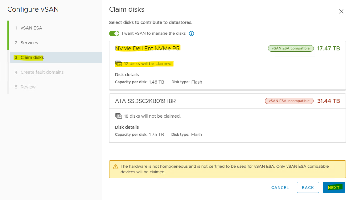
Create and Configure a VMware vSAN ESA
To create and configure a VMware vSAN ESA cluster please use the following document RDG for VMware vSAN ESA over NVIDIA RoCE on VMware vSphere 8.0 - Solutions - NVIDIA Networking Docs
RDMA is not supported in VMware vSphere 8.0b Distributed Services Engine. To run RDMA vSAN you can use additional ConnectX-6 Dx network card and use the card for vSAN RDMA traffic.
Samples of vSAN configuration screens.


Enable DRS and HA on Cluster
To enable DRS and HA on the SL-WL01-Cluster01 vSphere Cluster.
Open a browser, connect to vSphere web interface at https://<vcenter_fqdn>, and login with the administrator@vsphere.local account.
On the Inventory tab, select the cluster (SL-WL01-Cluster01), select Configure, select vSphere DRS, then select Edit….
On the Edit Cluster Settings page, enable vSphere DRS, then click Ok.


Check and apply LCM compliance.

To enable HA on the SL-WL01-Cluster01 vSphere Cluster.
Open a browser, connect to vSphere web interface at https://<vcenter_fqdn>, and login with the administrator@vsphere.local account.
On the Inventory tab, select the cluster (SL-WL01-Cluster01), select Configure, select vSphere DRS, then select Edit….
Enable vSphere HA, and click OK.

Check and apply LCM compliance.
Create and Configure an Offloaded Distributed Virtual Switch
A regular distributed switch with portgroups for the vMotion, and vSAN traffic should be created to ensure consistent network settings between the hosts.
Launch the vSphere Web Client and connect to a vCenter Server instance.
On the vSphere Web Client home screen, click on Inventory Networking tab.
Right click on the datacenter (SL-Datacenter), select the Distributed Switch, then click New Distributed Switch (see image below) to launch the New VDS creation wizard.

In the Name and location menu, set the name (SL-WL01-DS02) of the new distributed switch and select the location within the vCenter inventory where you would like to store the new VDS (a data center object or a folder).
Click NEXT.

In the Switch version menu, select 8.0.0 – ESXi 8.0.0 and later.
Click NEXT.
In the Configure settings menu:
set the Network Offloads compatibility as NNVDIA BlueField
set the Number of uplinks as 2
uncheck the Create a default port group box
Click NEXT.

In the Ready to complete menu, click Finish.

Set the MTU and Discovery protocol for the newly created distributed switch.
Right-click the new distributed switch in the list of objects and select Settings → Edit Settings... from the Actions menu.

In the SL_W01-DS02 Distributed Switch - Edit Settings dialog box, in the Advanced tab, set:
MTU to 9000
Discovery protocol Type to Link Layer Discovery Protocol Operation
Operation to Both
Click OK.

Adding Hosts to VDS
To add an ESXi host to an existing VDS:
Launch the vSphere Web Client, and connect to the vCenter Server instance.
Navigate to the list of Hosts in the SL-WL01-Cluster01 and select ESXi host.
Select Configure → Networking → Physical adapters.
Check the network ports that you are going to use. In this case, vmnic0 will used.
Navigate to the list of distributed switches.
Right-click the new distributed switch in the list of objects and select Add and Manage Hosts from the Actions menu.

In the Select task menu, check the Add hosts option and click NEXT .

In the Select hosts menu, select all the ESXi hosts you would like to add to the V DS .
Click NEXT.
In the Manage physical adapters menu, select the Adapters on all hosts tab and c onfigure vmnic0 in an ESXi host as Uplink 1 for the VDS .
WarningIn case you added the ConnectX-6DX please select the card first port (vmnic0) as Uplink1 and second port (vmnic1) as Uplink2.

In the Manage VMkernel adapters and Migrate VM networking menus click NEXT to continue.

In the Ready to complete menu, click FINISH.

Creating Distributed Port Groups for Virtual Machines SR-IOV Traffic
Right-click on Distributed switch, and select Distributed Port Group → New Distributed Port Group.

In the Name and location menu, set the Name (SL-WL01-SRIOV-1650) and click NEXT.

In the Configure settings menu:
set the VLAN type as VLAN
set VLAN ID as 1650
check the Customize default policies configuration checkbox
Click NEXT.

In the Security menu click NEXT.

In the Traffic shaping menu click NEXT .

In the Teaming and failover menu, set Uplink 1 as active and Uplink 2 as standby.
Click NEXT.

In the Monitoring menu, set NetFlow to Disabled , and click NEXT.

In the Miscellaneous menu, set Block All Ports to No , and click NEXT.

In the Ready to complete menu review all the changes before you click FINSIH.

NSX Manager Deployment and Configuration
NSX Manager Deployment
Prerequisites
Below are the prerequisites for deploying NSX Manager.
Necessary resources exist on the cluster to deploy NSX-Manager appliance
Port group for Management network (it is preferable to keep on the same network as vCenter)
4 free IPs from management network for NSX Managers (in this guide only one appliance is deployed)
NSX License
Create DNS A rerecords for NSX-Manager Hostnames
Management network netmask and gateway
NTP servers
Make sure nslookup is working for vCenter hostname and IP Address

Password for the NSX root user
Password for the NSX admin user
Password for the NSX audit user
Network Latency Requirements
The maximum network latency between NSX Managers in a NSX Manager cluster is 10ms
The maximum network latency between NSX Managers and Transport Nodes is 150ms
Storage Requirements
The maximum disk access latency is under 10ms
It is recommended that NSX Managers are placed on a shared storage
Storage should be highly available to avoid a storage outage causing all NSX Manager file systems to be placed into read-only mode upon a storage failure event
Please see the documentation for your storage technology on how to optimally design a highly available storage solution.
Deployment
Download the NSX manager OVA from VMware Customer Connect portal.


Login to the Management Cluster vCenter.
Click Host and Clusters, right click on a ESXi where you would like the NSX Manager to be deployed at and click Deploy OVF Template.

Select Local file → browse the OVA file for NSX Unified appliance .


Click NEXT.
Assign a Virtual machine name (sl-wl01-nsx01) and select the location were you want to place the NSX manager and click NEXT.

Select the compute resource whe re you want to place your NSX manager ( i.e., the cluster, resource pool, or the host), check its compatibility, and c lick NEXT.

Review the details and c lick NEXT.

Select deployment size (Medium), click NEXT .
 Warning
When selecting "Small" as the deployment configuration, some of the services do not work. Always use "Medium" or "Large".
Select the Storage/datastore where NSX manager should be placed and c lick NEXT.

Select the Management network and click NEXT to move to the "Customize Template" screen .

Specify the System GRUB root, System root account’s, admin and audit user passwords.
S croll down .
WarningStrong password is required.


Provide the Hostname, Rolename (NSX Manager has 3 roles, as seen below), and Management networking details.
Scroll down .

Assign the DNS and NTP details and choose whether SSH needs to be enabled on the NSX Manager.
Click NEXT .

Review the details and click FINISH . Wait for the NSX manager appliance to be successfully deployed.

The NSX Manager will be deployed after about 5-10 minutes .
Once the appliance is successfully deployed, Power on and wait for at least 15 minutes for all the services to come up.
Once the services are up, a login prompt is shown. At this point, wait 10 more minutes as backend services need to start the web-portal-related services.

Post-Deployment Health Checks
Once done, do the following post-deployment steps:
Open the console and try to log in with admin credentials using putty. You will see the version number and the role.

Verify the network configuration by using the command below.
NSX manager console
get interface eth0

Check the services status by running the following command.
NSX manager console
get services
 Warning
Liagent, migration-coordinator and SNMP services are not started by default.
NSX Manager Configuration
Log in to NSX manager UI login page by using the URL " https://<fqdn or IP> ".

Accept the EULA on the first login to the NSX manager.

Decide whether or not to join the Customer Experience Improvement Program.

Take a quick tour, in case you need.

Finally, the NSX manager is presented.

Navigate to System → Licenses and click on +ADD LICENSE.

Add a license and click ADD.


Adding a Compute Manager
To add a compute manager, navigate to System → Fabric → Compute Managers, click ADD COMPUTE MANAGER to add vCenter as compute manager.

Fill in the vCenter details → click ADD.

Click ADD , when presented with the vCenter server thumbprint window.

Wait for registration to complete. T he status will be changed to registered and connection status to "Up".

Create an Uplink Profile
An uplink profile defines the policies for links from a hypervisor hosts to the NSX logical switches or from NSX Edge nodes to top-of-rack switches. The settings defined by these profiles may include teaming policies, active/standby links, transport VLAN ID, and MTU settings. Uplink profiles enables consistent configuration of identical capabilities for network adapters across multiple hosts and nodes. By default, there are two uplink profiles that are provided with NSX and cannot be edited, that is why new profiles for the Edge uplink should be created (for hosts’ uplinks as well).
To create a Host uplink profile in NSX Manager, do the following:
Navigate to System → Fabric → Profiles → Uplink Profiles → +ADD PROFILE.

Assign a name to the profile and fill the description.
Under Teamings, set the Teaming Policy to Failover Order.
Set the Active Uplinks to uplink-1.
The Transport VLAN will be an Overlay VLAN ID (in the example provided,1640) since these uplinks are connected directly to the hosts and need to be tagged accordingly. MTU not fill .
Click ADD.


Create a Transport Zone
Transport Zones dictate which hosts (and consequently which VMs) can participate in the use of a particular network. There are two types of transport zones: an overlay and a VLAN.
The overlay transport zone is used by both host transport nodes and NSX Edges and is responsible for communication over the overlay network.
The VLAN transport zone is used by the NSX Edge for its VLAN uplinks.
Both types create an N-VDS on the host or Edge to allow for virtual-to-physical packet flow by binding logical router uplinks and downlinks to physical NICs.
To create Transport Zone with Overlay Traffic Type
To create a Transport Zone in the NSX Manager, navigate to System → Fabric → Transport Zones → +ADD ZONE.

Provide a Name and select the Traffic Type as Overlay (Geneve) and then click ADD.


Create a NSX TEPs IP Pool
Each transport node (i.e., hypervisors) is assigned with an IP address for the TEP interface. DHCP, Static IP List, and IP address Pool can all be used for assigning IP addresses for the TEP (Tunnel Endpoint) interfaces. To configure the ESXi hosts as Transport nodes, NSX IP Pool will be created to assign IP addresses for the TEP interfaces.
To create an IP Pool, in the NSX Manager, do the following:
Navigate to Networking → IP Address Pools → ADD IP ADDRESS POOL.

Specify the name and description of the IP address pool. Click Set.

Click ADD SUBNET and select IP Ranges.

Specify the IP Address Ranges, along with CIDR and Gateway IP, address for the specified IP ranges. Click ADD.

Click Apply.

Click SAVE to create the IP Pool.

Once the IP Pool is created, the status will be changed to Success.

Installing NSX Components on a Host Transport Node(ESXi/ESXio).
Navigate to System → Fabric → Hosts → Clusters. Select SL-WL01-Cluster01. Click Configure NSX.

In the Transport Node Profile, click the three dots menu to Create a New Transport Nodes Profile.

Specify the Name → SL-WL01-TNP-EDP-STD and description, and click the Set.

Click ADD HOST SWITCH.
Select Name of vCenter → sl-wl01-vc01 and VDS → SL-WL01-DS02.
Select Transport Zones were created before → SL-WL01-Overlay-TZ.
Select the Uplink Profile → Uplink-profile-01.
Select the IP Assignment (TEP) → Use IP Pool.
Select the IP Pool → SL-WL01-TEP-IPPool.
Select Mode → Enhanced Datapath - Standard.
WarningVDS Modes:
Standard applies to all the supported hosts.
Enhanced Datapath - Standard is an interrupt driven variant of the Enhanced Data Path mode.
Enhanced Datapath - Performance is the Enhanced Data Path switch mode. This mode provides accelerated networking performance, but also introduces additional prerequisites. In order to benefit from this mode, workloads must be compiled with DPDK and use VMNET3 for their vNIC.
In Team Policy Uplink Mapping Select uplink-1 → Uplink 1.
WarningIn case you added the ConnectX-6DX please select uplink-1 → Uplink 1 and uplink-2 → Uplink 2.
Click ADD.

Click APPLY.

Click SAVE.

Select the Transport Nodes Profile we created (SL-WL01-TNP-EDP-STD) and click SAVE.

You can see the installation is progressing.

In the vSphere client.

Wait until the hosts are successfully installed, the NSX Configuration status is “ Success ” and the Status indicators are “ Up ”.

In the Inventory tab, select the cluster (SL-WL01-Cluster01), select Updates, select Image. Image compliance should show compliant prior to moving on to next steps.

Create an NSX Tier-1 Gateway
Navigate to Networking -> Tier-1 Gateway and click on Add Tier-1 Gateway.

Provide a name for the Tier-1 Gateway (T1-GW) and click on Save to complete creation of the Tier-1 Gateway.

Select NO in response to Do you want to continue configuring this Tier-1 Gateway?

The T1-GW Tier-1 Gateway is successfully created.

Create an Overlay Segment with Offload Switches
Navigate to Networking -> Segments and click on Add Segments,

Provide a name for the Segment (SL-WL01-Seg01), Connected Gateway (T1-GW), Transport Zone (SL-WL01-Overlay-TZ), Subnets: 10.10.10.1/24.
Click on Save to complete creation of the Segment,

Select NO in response to Do you want to continue configuring this Segment?.

The SL-WL01-Seg01 segment is successfully created.

Ensure that you see the segment in vSphere client.

Validation
Log into the ESXi console.
Check the FPO model on ESXi.
Log into the ESXi console with root permissions, and run the following commands in the ESXi CLI to view information about the VDS switch and VMK interface(s).
ESXi Host Console
[root@clx-host-153:~] esxcfg-vswitch -l

ESXi Host Console
[root@clx-host-153:~] esxcfg-vmknic -l

Check the FPO model on the VDS (SL-WL01-DS02) switch.
ESXi Host Console
[root@clx-host-153:~] nsxdp-cli ens fpo get -dvs SL-WL01-DS02

On ESXi Check the running FPO Model on the vmnic0 (in our environment).
ESXi Host Console
[root@clx-host-153:~] nsxdp-cli ens fpo status get -n vmnic0

Check the FPO model on ESXio.
Log into the ESXio console with sshdpu command.
 Warning
In case you see the "Connection refused" message. Run the following commands on the ESXi host to open SSH to ESXio.
ssh: connect to host 169.254.100.2 port 22: Connection refused
[root@clx-host-153:~] vim-cmd combinersvc/dpu_services/set_policy TSM-SSH on vmdpu0
[root@clx-host-153:~] vim-cmd combinersvc/dpu_services/start TSM-SSH vmdpu0
Run the following commands in the ESXio CLI to view information about the VDS switch and VMK interface(s).
ESXio Host Console
[root@clx-host-153-oob:~] esxcfg-vswitch -l

ESXio Host Console
[root@clx-host-153-oob:~] esxcfg-vmknic -l

Check the FPO model on the VDS (SL-WL01-DS02) switch.
ESXi Host Console
[root@clx-host-153-oob:~] nsxdp-cli ens fpo get -dvs SL-WL01-DS02

On ESXio check the running FPO Model on the vmnic0 (in our environment).
ESXi Host Console
[root@clx-host-153-oob:~] nsxdp-cli ens fpo status get -n vmnic0

Create a Linux VM.
To create a Linux VM.
Right-click Host in the VMware Host Client inventory and select New Virtual Machine...
The New Virtual Machine wizard opens.
Select a name and a location for the VM and click NEXT.
On the Select a compute resource, select an ESXi host and click NEXT.
On the Select storage page, select the storage type for the virtual machine and a datastore where to store the virtual machine files.
To save all the virtual machine disks and configuration files on a standard datastore, click the Standard button.
To save the virtual machine hard disks on the host-local PMem datastore, click the Persistent Memory button.
Select a datastore from the list and click Next.
Ensure that the VM Storage is mapped to vSANDatastore or another shared datastore, if the intent is to be able to vMotion.
Click Next.
On the Select compatibility page, select Compatible with: ESXI 8.0 and later. Click NEXT.
On the Select a guest OS page, configure the guest operating system.
From the Guest OS family drop-down menu, select the guest operating system.
From the Guest OS version drop-down menu, select the guest operating system version.
WarningFor UPTv2 VM make sure what OS from the supported list - https://kb.vmware.com/s/article/90548?lang=en_US
On the Customize hardware page, configure the virtual machine hardware and options and click Next.
On the Customize settings page, click Virtual Hardware and add a new virtual hardware device.
Add the first Network Adapter “New Network” to the Management Port Group(VM network),
Click the ADD NEW DEVICE → Network Adapter icon to add a second NIC to the virtual machine.
And add the second Network Adapter “New Network *” to the SL-WL01-Seg01 NSX Segment in the lab network.
Select Adapter Type: VMXNET3.
For UPTv2 VM select Use UPT Support: Enabled .

For SR-IOV interface select Adapter Type: PCI Device passthrough.

Connect ISO File with an Linux OS.
(Optional) To customize virtual machine options, click the VM Options button.

UPTv2 Interface Validation
To validate if programming the interface in UPTv2 mode was successful, verify that the state of the Port is set to PT_UPT.
On the host run the following commands:
ESXi Host Console
[root@clx-host-153:~] net-stats -l

Make sure the PortNum and the SwitchName corresponding to the interface on the UPTv2 VM attached to the NSX
Segment (highlighted in the output above):
ESXi Host Console
[root@clx-host-153:~] vsish -e get /net/portsets/DvsPortset-1/ports/134217763/vmxnet3/ptSummary

To verify network connectivity and vMotion.
Log into the ESXi console.
Log into the ESXio console with sshdpu command.
In case you see the "Connection refused" message. Run the following commands on the ESXi host to open SSH to ESXio.
ssh: connect to host 169.254.100.2 port 22: Connection refused
[root@clx-host-153:~] vim-cmd combinersvc/dpu_services/set_policy TSM-SSH on vmdpu0
[root@clx-host-153:~] vim-cmd combinersvc/dpu_services/start TSM-SSH vmdpu0
Run the following command in the ESXio CLI to view information about the VDS switch using ports.
ESXio Host Console
[root@clx-host-153-oob:~] esxcfg-vswitch -l

Check or set IP on UPT VMs second interface (ens35).

Run the ping command from the first UPT VM (clx-vm-upt-01) to the second UPT VM (clx-vm-upt-02) and migrate the first UPT VM (clx-vm-upt-01) to another host(not when the second UPT VM (clx-vm-upt-02) is runing).


To verify Traffic Offloadinging.
Run the ping command from the first UPT VM (clx-vm-upt-01) to second UPT VM (clx-vm-upt-02).

Log into the ESXi console.
Run the following command in the ESXi CLI to view the flow table dump from x86.
ESXio Host Console
[root@clx-host-153:~] nsxdp-cli ens flow-table dump
As expected, the table is empty.

Now, log into the ESXio console with sshdpu command.
In case you see the "Connection refused" message. Run the following commands on the ESXi host to open SSH to ESXio.
ssh: connect to host 169.254.100.2 port 22: Connection refused
[root@clx-host-153:~] vim-cmd combinersvc/dpu_services/set_policy TSM-SSH on vmdpu0
[root@clx-host-153:~] vim-cmd combinersvc/dpu_services/start TSM-SSH vmdpu0
Run the following command in the ESXio CLI to view information about the VDS switch using ports.
ESXio Host Console
[root@clx-host-153-oob:~] nsxdp-cli ens flow-table dump
The tables shows that the ping operation for UPT VMs is offloaded.

Stop the ping command from the first UPT VM (clx-vm-upt-01) to the second UPT VM (clx-vm-upt-02).
Done!
Authors

|
Boris Kovalev Boris Kovalev has worked for the past several years as a Solutions Architect, focusing on NVIDIA Networking/Mellanox technology, and is responsible for complex machine learning, Big Data and advanced VMware-based cloud research and design. Boris previously spent more than 20 years as a senior consultant and solutions architect at multiple companies, most recently at VMware. He has written multiple reference designs covering VMware, machine learning, Kubernetes, and container solutions which are available at the Mellanox Documents website. |