Installation
Installation and initialization of the system require attention to the normal mechanical, power, and thermal precautions for rack-mounted equipment.
The rack mounting holes conform to the EIA-310 standard for 19-inch racks. Take precautions to guarantee proper ventilation in order to maintain good airflow at ambient temperature.
Unless otherwise specified, NVIDIA products are designed to work in an environmentally controlled data center with low levels of gaseous and dust (particulate) contamination.
The operation environment should meet severity level G1 as per ISA 71.04 for gaseous contamination and ISO 14644-1 class 8 for cleanliness level.
The installation procedure for the system involves the following phases:
|
Step |
Procedure |
See |
|
1 |
Follow the safety warnings |
|
|
2 |
Pay attention to the air flow consideration within the system and rack |
|
|
3 |
Make sure that none of the package contents is missing or damaged |
|
|
4 |
Mount the system into a rack enclosure |
|
|
5 |
Power on the system |
|
|
6 |
Perform system bring-up |
|
|
7 |
[Optional] FRU replacements |
Prior to the installation, please review the safety warnings. Note that not all warnings may apply to all models.
Prior to the installation, please review the safety warnings. Note that not all warnings may apply to all models.
Safety warnings are provided here in the English language. For safety warnings in other languages, refer to the 1U Switch Installation Safety Instructions document.
Safety Warnings (English)

Installation Instructions
Read all installation instructions before connecting the equipment to the power source.

Bodily Injury Due to Weight
Use enough people to safely lift this product.
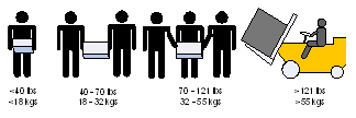
Heavy Equipment
This equipment is heavy and should be moved using a mechanical lift to avoid injuries.
Risk of Electric Shock!
With the fan module removed power pins are accessible within the module cavity.
Do not insert tools or body parts into the fan module cavity.
For AC powered switch systems: Disconnecting one power supply only disconnects one module. To isolate the unit completely, all connected power supplies must be disconnected.
In QM97X0/NVLink switch systems: for 200-240Vac use only
Over-temperature
This equipment should not be operated in an area with an ambient temperature exceeding the maximum value listed in the product specifications. Moreover, to guarantee proper ventilation, allow at least 8 cm (3 inches) of clearance around the ventilation openings.
Stacking the Chassis
The chassis should not be stacked on any other equipment. If the chassis falls, it can cause bodily injury and equipment damage.
Redundant Power Supply Connection (OPTIONAL)—Electrical Hazard
This product includes a redundant power or a blank in its place. In case of a blank power supply, do not operate the product with the blank cover removed or not securely fastened.
Double Pole/Neutral Fusing
This system has double pole/neutral fusing. Remove all power cords before opening the cover of this product or touching any internal parts.
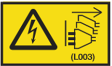
Multiple Power Inlets
Risk of electric shock and energy hazard. The PSUs are all independent. Disconnect all power supplies to ensure a powered down state inside of the switch platform.
During Lightning—Electrical Hazard
During periods of lightning activity, do not work on the equipment or connect or disconnect cables.
Copper Cable Connecting/Disconnecting
Copper cables are heavy and not flexible, as such they should be carefully attached to or detached from the connectors. Refer to the cable manufacturer for special warnings/instructions.
Rack Mounting and Servicing
When this product is mounted or serviced in a rack, special precautions must be taken to ensure that the system remains stable. In general, the rack should be filled with equipment starting from the bottom to the top.
Equipment Installation
This equipment should be installed, replaced, and/or serviced only by trained and qualified personnel.
Equipment Disposal
Disposal of this equipment should be in accordance to all national laws and regulations.
Local and National Electrical Codes
This equipment should be installed in compliance with local and national electrical codes.
Installation Codes
This device must be installed according to the latest version of the country national electrical codes. For North America, equipment must be installed in accordance to the applicable requirements in the US National Electrical Code and the Canadian Electrical Code.
Battery Replacement
Warning: Replace only with UL Recognized battery, certified for maximum abnormal charging current not less than 4mA. There is a risk of explosion should the battery be replaced with a battery of an incorrect type. Dispose of used batteries according to the instructions.
UL Listed and CSA Certified Power Supply Cord
For North American power connection, select a power supply cord that is UL Listed and CSA Certified, 3 - conductor, [16 AWG], terminated with a molded plug rated at 125 V, [13 A], with a minimum length of 1.5m [six feet] but no longer than 4.5m.
For European connection, select a power supply cord that is internationally harmonized and marked “<HAR>”, 3 - conductor, minimum 1.0 mm2 wire, rated at 300 V, with a PVC insulated jacket. The cord must have a molded plug rated at 250 V, 10 A.
Installation Codes
This device must be installed according to the latest version of the country's national electrical codes. For North America, equipment must be installed in accordance to the applicable requirements in the US National Electrical Code and the Canadian Electrical Code.
Interconnection of Units
Cables for connecting to the unit RS232 and Ethernet Interfaces must be UL certified type DP-1 or DP-2. (Note: when residing in non LPS circuit.)
Overcurrent Protection
A readily accessible Listed branch circuit overcurrent protective device rated 20 A must be incorporated in the building wiring.
Acoustic Level Warning
The acoustic level listed in Specifications section represents product noise measured in accordance with ISO 7779 under nominal conditions. The actual noise level can vary depending on the installation conditions, including but not limited to the number of racks in the installation, the overall installation size, rack and other equipment material and noise levels, fan faults, room temperature, room configuration, and employee location in relation to the equipment. The data-center owner should manage effective hearing conservation as per the OSHA standard to protect employees against over and extended exposure to noise.

Do Not Use the Switch as a Shelf or Work Space
Caution: Slide/rail mounted equipment is not to be used as a shelf or a work space. The rails are not intended for sliding the unit away from the rack. It is for permanent installation at final resting place only, not used for service and maintenance.

WEEE Directive
According to the WEEE Directive 2002/96/EC, all waste electrical and electronic equipment (EEE) should be collected separately and not disposed of with regular household waste. Dispose of this product and all of its parts in a responsible and environmentally-friendly way.
Country of Norway Power Restrictions
This unit is intended for connection to a TN power system and an IT power system of Norway only.
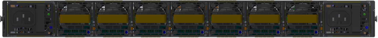
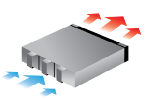
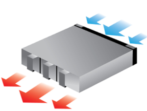
NVIDIA systems are offered with two air flow patterns:
Power (rear) side inlet to connector side outlet - marked with blue power supplies/fans FRUs’ indicators.
Air Flow Direction Marking - Power Side Inlet to Connector Side Outlet
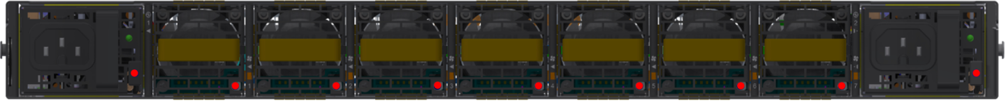
Connector (front) side inlet to power side outlet - marked with red power supplies/fans FRUs’ indicators.
Air Flow Direction Marking - Connector Side Inlet to Power Side Outlet
All servers and systems in the same rack should be planned with the same airflow direction.
All FRU components need to have the same air flow direction. A mismatch in the air flow will affect the heat dissipation.
The table below provides an air flow color legend and respective OPN designation.
|
Direction |
Description and OPN Designation |
|
Power side inlet to connector side outlet. Blue indicators are placed on the power inlet side. The P2C OPN is 920-24697-0000-000. |
|
Connector side inlet to power side outlet. Red indicators are placed on the power inlet side. The C2P OPN is 920-24697-0000-001. |
Before installing your new system, unpack it and check against the parts list below that all the parts have been sent. Check the parts for visible damage that may have occurred during shipping.
The NVLink Switch System package content is as follows:
1 – System
1 – Sliding rail kit
4 – Power cables Type C14 to C15
1 - Harness: HAR000631 – Harness RS232 2M cable – DB9 to RJ-45
2 – Cable retainers
32 - OSFP thermal caps
If anything is damaged or missing, contact your NVIDIA representative at Networking-support@nvidia.com.
By default, the systems are shipped with the rail kit described in Tool-less Sliding Rail Kit.