cuPHY
cuPHY is a CUDA implementation of 5G PHY layer signal processing functions. The cuPHY library supports all 5G NR PHY channels in compliance with 3GPP Release 15 specification. The functional coverage of cuPHY library is shown in the following figure. It corresponds to upper PHY stack according to O-RAN 7.2x split option.

cuPHY library within 5G NR software stack
cuPHY is optimized to take advantage of massive parallel processing capability of the GPU architecture by running the workloads in parallel as much as possible. cuPHY tasks are organized according to the PHY layer channel type, e.g. PDSCH, PUSCH, SSB, etc. The tasks related to a given channel is termed as pipeline. For example, functions related to encoding of PDSCH channel is called PDSCH pipeline. Similarly, functions related to decoding of the PUSCH channel is called PUSCH pipeline. Each pipeline includes series of functions related to the specific pipeline and consists of multiple CUDA kernels. Each pipeline is capable to run signal processing workloads for multiple cells. They are managed by cuPHY driver channel aggregate objects. [todo include corresponding explanation in cuphy driver]. Channel pipelines are managed dynamically for each slot. Therefore, group of channel pipelines in a given slot depends on the L1 channel configuration.
The cuPHY library exposes a set of APIs per PHY channel to create, destroy, setup, configure and run each pipeline as shown in the following figure. L2 adapter translates SCF FAPI messages and other system configurations and invokes associated cuPHY APIs for each slot.
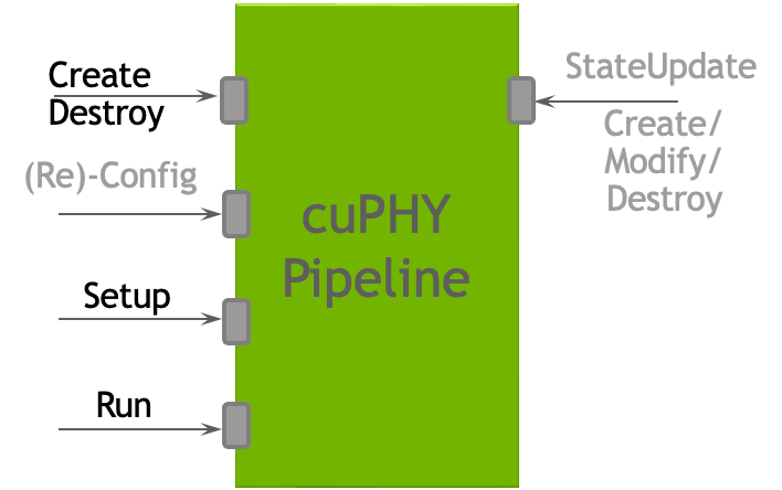
cuPHY API interface [replace this figure for the new format].
In the following sections, more details are provided on the implementation of each PHY channel pipeline.
The PDSCH pipeline receives DL transport blocks (TBs) and configuration parameters for each TB. It outputs IQ samples mapped to RE corresponding to the PDSCH.
The PDSCH pipeline contains the following high level components:
CRC calculation
LDPC encoder
Fused Rate Matching (which also includes scrambling and layer mapping) and Modulation Mapper
DMRS generation
The CRC calculation component performs the code block segmentation and the CRC calculation. The CRC is calculated first for each TB and then for each code block (CB). The fused rate matching and modulation component performs rate-matching, scrambling, layer-mapping, precoding and modulation. This component is also aware of which resource elements it should skip because of CSI-RS if applicable.
As of Rel-23-4, the full PDSCH pipeline involves the following kernels:
prepare_crc_bufferscrcDownlinkPdschTransportBlockKernelcrcDownlinkPdschCodeBlocksKernelldpc_encode_in_bit_kernelfused_dl_rm_and_modulationfused_dmrs
Kernels exercised only if CSI-RS parameters are present:
zero_memset_kernelgenCsirsReMappostProcessCsirsReMap
The cuPHY PDSCH Tx pipeline populates parts of a 3D tensor buffer of I/Q
samples in GPU memory, where each sample is a complex number using
fp16, i.e., each sample is a \__half2 using x for the real part
and y for the imaginary part. The output 3D tensor buffer is
allocated by the controller, and is reset for every slot (i.e., between
successive PDSCH launches) from the cuPHY driver. Here, resetting the
buffer means, it is initialized to all zero values.
The output tensor contains 14 symbols (x-axis, for time domain), 273
PRBs (Physical Resource Blocks) (y-axis, frequency), and up to 16
layers (z-axis, for spatial domain). For the y-axis, each PRB
contains 12 Res (Resource Elements), and each RE is a \__half2
data. Contiguous PRBs for the same OFDM symbol and spatial layer are
allocated next to each other on memory. The resources are mapped in
memory in the following order: frequency, OFDM symbols and then the
layers.
The PDSCH only fills parts of that buffer, i.e., its allocated PRBs,
based on various configuration parameters it receives that vary over
time. Parts of the slot can be filled by other downlink control
channels. From a PDSCH standpoint, only the two fused_ kernels
listed above, fused_dl_rm_and_modulation and fused_dmrs write to
the output buffer. The fused rate-matching and modulation kernel writes
the vast majority of the I/Q samples, while the DMRS kernel only writes
the DMRS symbols, i.e., only 1 or 2 contiguous symbols in the
x-dimension. Note that, unlike other components, DMRS is not dependent
on any of the previous pipeline stages.
The PDSCH pipeline expects pre-populated
structs cuphyPdschStatPrms_t and cuphyPdschDynPrms_t that
include the input data and the necessary configuration parameters.
The TB data input can exist either in CPU or GPU memory depending on the
cuphyPdschDataIn_t.pBufferType. If this is GPU_BUFFER, then the host
to device (H2D) memory copies for that data can happen before PDSCH
setup is executed per each cell. This is called prepone H2D copy and can
be configured by setting the prepone_h2d_copy flag in the
l2_adapter_config_*.yaml file. If prepone H2D copy is not enabled, the
copy operations happen as part of PDSCH setup. It is highly recommended
that the prepone H2D copy should be enabled to achieve high capacity in
a multiple cell scenario.
The way LDPC kernels are initiated can change when multiple TBs are configured on PDSCH. If the LDPC configuration parameters are identical across TBs, PDSCH launches a single LDPC kernel for all TBs (as is the case for the other PDSCH components). If the LDPC configuration parameters vary across the TBs, then multiple LDPC kernels are launched, one for each unique configuration parameters set. Each LDPC kernel is launched on a separate CUDA steam.
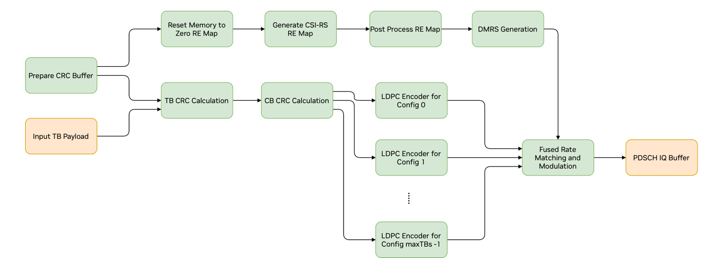
Graph Diagram of the PDSCH Pipeline
The PDSCH CUDA graph contains only kernel nodes and has the layout shown in the above figure. As it is not possible to dynamically change the graph geometry at runtime, PDSCH_MAX_N_TBS_SUPPORTED potential LDPC kernel nodes are created. Depending on the LDPC configuration parameters and the number of TBs, only a subset of these perform LDPC encoding. The remaining nodes are disabled at runtime if needed per PDSCH. The DMRS kernel node is not dependent on any of the other PDSCH kernels. Therefore, it can be placed anywhere in the graph. The three kernels preceding the DMRS in the graph are only exercised if CSI-RS parameters are present. They compute information needed by the fused rate matching and modulation kernel about Res that need to be skipped.
Configuration parameters used by PDSCH are spread across multiple datasets and are split in two groups: (a) static parameters and (b) dynamic parameters.
Static parameters are specified in the cellStat_pars dataset. These parameters cannot change during a PdschTxobject’s lifetime.
Dynamic parameters are specified in the the following datasets: cellGrpDyn_pars, cellDyn_pars, ueGrp_pars, ue_pars, cw_pars, dmrs_pars, csirs_pars, tb*_PM_W These parameters do change during the PdschTxobject’s lifetime and are updated during PdschTxset-up.
As of Rel-23-4, the cuPHY PDCCH channel processing involves the following kernels:
encodeRateMatchMultipleDCIsKernel
genScramblingSeqKernel
genPdcchTfSignalKernel
When running in graphs mode, the CUDA graph launched on every slot contains only kernel nodes and its current layout is as depicted in the following figure.

cuPHY PDCCH graph layout
PDCCH kernel takes static and dynamic parameters as in PDSCH.
Notes on PDCCH configuration and dataset conventions:
The PdcchParams dataset contains the coreset parameters for a given cell. Dataset DciParams_coreset_0_dci_0 contains the DCI parameters for the first DCI of coreset 0. There is a separate dataset for every DCI in a cell with the naming convention: DciParams_coreset_<i>_dci_<j>, wherei *has values from *0 up to (number of coresets – 1), while j starts from 0 for every coreset i and goes up to (PdcchParams[i].numDlDci – 1) for that coreset.
Dataset DciPayload_coreset_0_dci_0 contains the DCI payload, in bytes, for the first DCI of coreset 0. It follows the naming convention mentioned above DciParams_coreset_0_dci_0.
Dataset(s) DciPmW_coreset_i_dci_j hold the precoding matrix for a given DCI, coreset pair, if it has precoding enabled.
X_tf_fp16 is the 3D output tensor for that cell and is used for reference checks in the various PDCCH examples.
X_tf_cSamples_bfp* datasets that contain compressed data are not used in cuPHY, since compression happens in cuphydriver after all cuPHY processing for all downlink channels scheduled in a slot has completed.
As of Rel-23-4, the cuPHY SS Block channel processing involves the following kernels:
encodeRateMatchMultipleSSBsKernel
ssbModTfSigKernel
When running in graphs mode, the CUDA graph launched on every slot contains only these two kernel nodes connected in sequence.
Notes on SSB configuration and dataset conventions:
The* SSTxParams* dataset contains all the nSsb, SSB parameters for a given cell.
SSB bursts cannot be multiplexed in frequency domain, they can only be multiplexed in time domain.
nSsb datasets contains the number of SSBs in a cell, this is also the size of the SSTxParamsdataset.
x_mib contains the Master Information Block (MIB) for each SSB in the cell as an uint32_t element; only the least significant 24-bits of each element are valid.
Dataset(s) Ssb_PM_W* contain the precoding matrices if precoding is enabled for a given SSB.
X_tf_fp16 is the 3D output tensor for that cell and is used for reference checks in the various SSB examples. Every I/Q sample there is stored as __half2c. X_tf *is similar to *X_tf_fp16 but every I/Q sample there is stored as float2 instead of __half2; not currently used in cuPHY.
X_tf_cSamples_bfp* datasets hold the output compressed and are not used in cuPHY as compression is applied as part of the cuphydriver.
For Rel-23-4, the cuPHY CSI-RS channel processing involves the following kernels:
genScramblingKernel
genCsirsTfSignalKernel
When running in graphs mode, the CUDA graph launched on every slot contains only these two kernel nodes connected in sequence.
Notes on CSI-RS configuration and dataset conventions:
CsirsParamsListcontains configuration parameters which are used for non-zero power signal generation (e.g., NZP, TRS).Please note that
CsirsParamsListdataset can have multiple elements. All elements in the dataset can be processed with single setup/run call.X_tf_fp16is the 3D reference output tensor for that cell and is used for reference checks in the various CSI-RS examples. Every I/Q sample there is stored as__half2c.X_tf `` is similar to ``X_tf_fp16but every I/Q sample there is stored asfloat2instead of__half2; not currently used in cuPHY.X_tf_cSamples_bfp*datasets hold the output compressed and are not used in cuPHY as compression is applied as part of cuphydriver.X_tf_remapis reference output for RE Map, this is not used currently as current implementation only generates NZP signal.Dataset(s)
Csirs_PM_W*contain precoding matrices and are used if precoding is enabled.
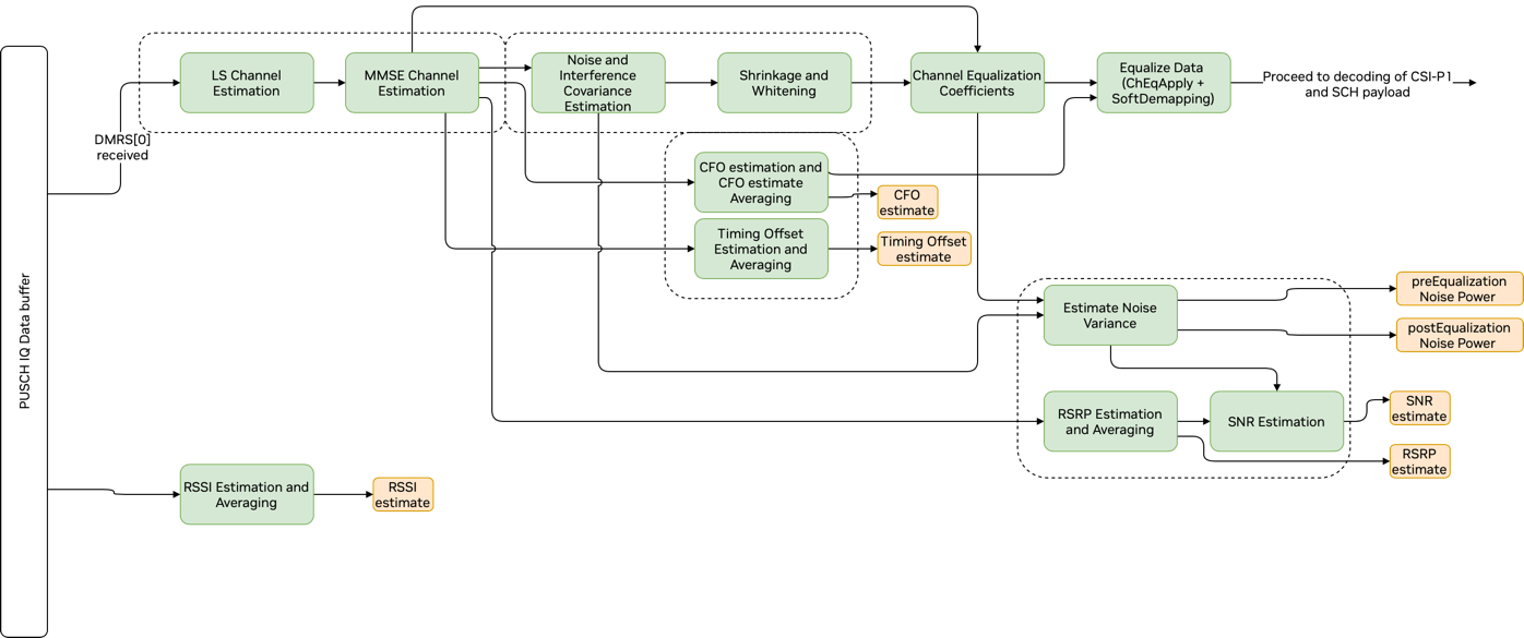
Graph Diagram of the PUSCH Pipeline Front End
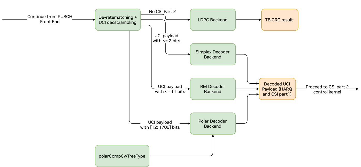
Graph Diagram of the PUSCH and CSI Part 1 Decoding
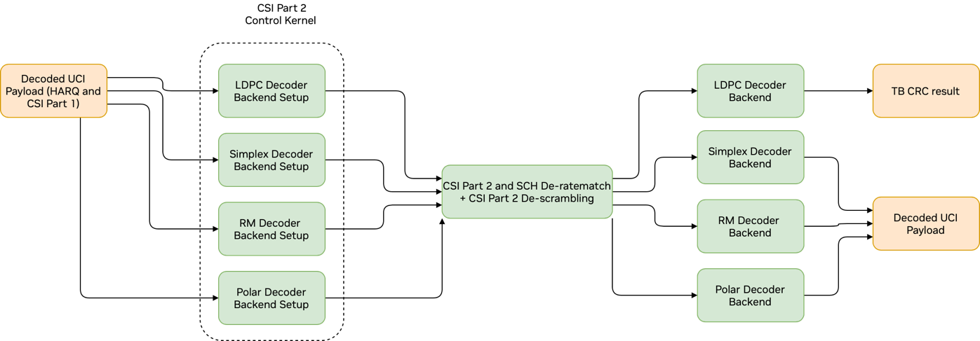
Graph Diagram of the PUSCH and CSI Part 2 Decoding
ASDK comes with a built-in doxygen documentation. The doxygen document generation is disabled by default and it needs to be enabled by using the flag -DBUILD_DOCS=ON during compilation. Once enabled, the created documentation can be found under $cuBB_SDK/build/cuPHY/docs/html.
By clicking on index.html file in this folder, the start up page can be launched as shown in the following figure.
cuPHY documentation start page
Modules tab includes list of main cuPHY functions as can seen in first figure below. As an example, details of the channel equalization module is shown in second figure below. It includes the declaration of the functions used by the module and detailed list of input and output arguments for each function.
The front page has also a link to the list of data structures used by ASDK. The contents of this link can be seen in the third figure below.
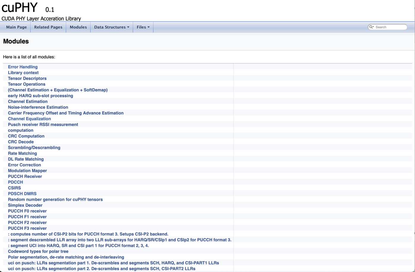
cuPHY modules
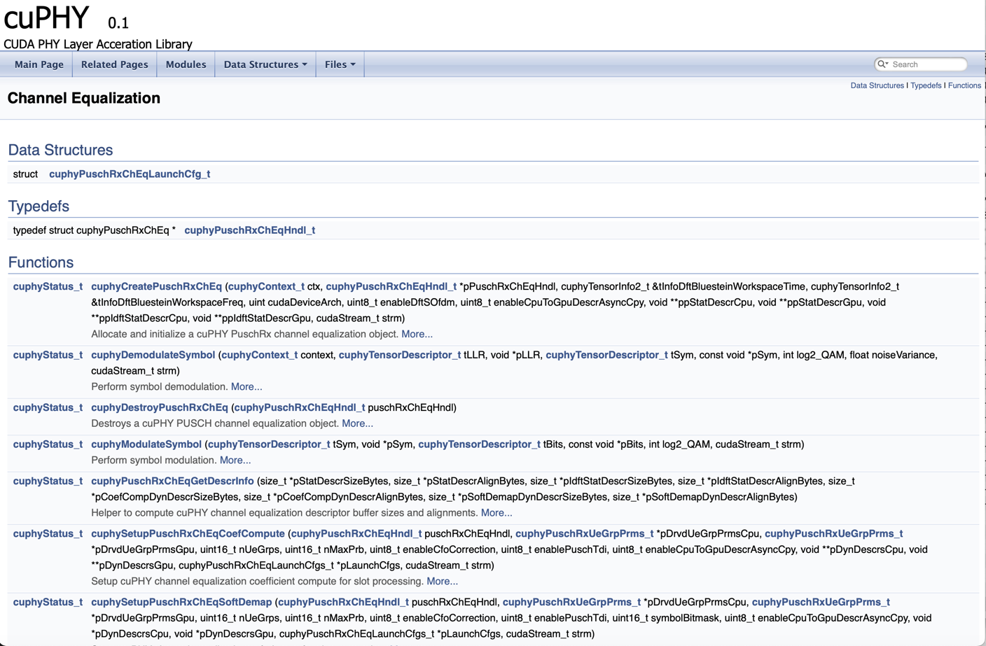
Channel equalization module
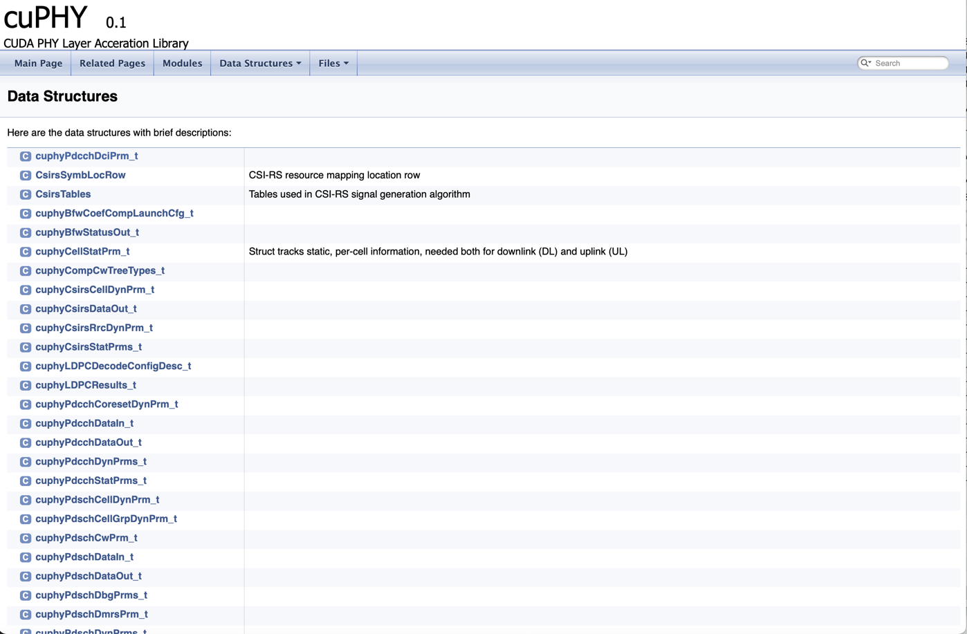
Data structures