L2 Adapter
The L2 Adapter is the interface between the L1 and the L2, which translates SCF FAPI commands to cuPHY tasks. It makes use of nvipc library to transport messages and data between L1 and L2. It is also responsible for sending slot indications to drive the timing of the L1-L2 interface.
The cuPHY driver is responsible for orchestrating the work on the GPU and the FH by using cuPHY and FH libraries. It processes L2 slot commands generated by L2 adapter to launch tasks and sends cuPHY outputs (e.g. CRC indication, UCI indication, measurement reports, etc.) back to L2. It uses L2 adapter FAPI message handler library to communicate with L2.
cuPHY driver configures and initiates DL and UL cuPHY tasks, which in turn launch CUDA kernels on the GPU. These processes are managed at the slot level. The cuPHY driver also controls CUDA kernels responsible for transmission and reception of user plane (u-plane) packets to and from the NIC interface. The communication tasks launched by the driver takes care of re-ordering and decompression for UL packets and compression of DL packets. The DL packets are transmitted by GPU initiated communication after the compression.
cuPHY driver interacts with the FH interface using ORAN compliant FH library to coordinate transmission of FH control plane (c-plane) packets. The transmission of c-plane packets are done via DPDK library calls (CPU initiated communication). The u-plane packets are communicated through transmit and receive queues created by the cuphycontroller.
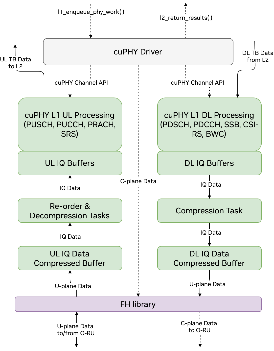
User and Control Plane Data Flow through cuPHY driver and cuPHY tasks
cuPHY Driver Thread Timing
[TODO] Needs to be provided by Srinivas
The FH library includes the driver and the NIC firmware. It ensures timely transmission and reception of FH packets between the O-DU and O-RU. It uses accurate send scheduling functions of the NIC to comply with the timing requirements of the O-RAN FH specification.
The FH driver maintains the context and connection per eAxCid. It is responsible of encoding and decoding of FH commands for U-plane and C-plane messages.
The Figure 4 shows the mapping of NIC HW resources to the peers maintained by the FH driver. In this example, NIC has 16 RX queues and 48 TX queues, which can be shared between different peers.
FH library usage for DU:
Each Cell is equivalent to a peer.
Each peer is set to RX mode PEER
Each peer has 1 RX Queue for all UL U-plane designated for the peer mac address
There are 3 TX Queues per cell, 1 for DL U, 1 for UL C, 1 for DL C
FH Library usage for RU Emulator:
RX mode FLOW
1 RXQ for each cell for each eAxC ID for DL U
1 additional RXQ per cell for the UL C/DL C plane
RU TX Before and including 23-1
RU uses 2 TXQ per cell, 1 for PUSCH and PUCCH section type 1, and another for PRACH section type 3
After 23-2
RU uses 28 TXQs total, for each symbol for odd and even slots
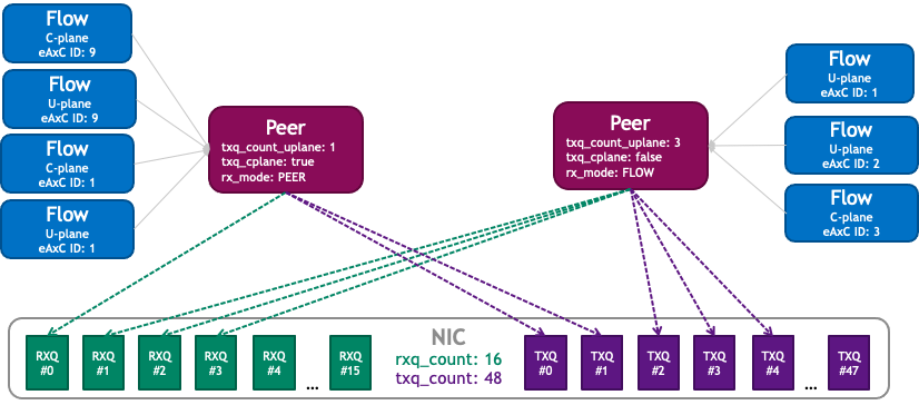
NIC HW resources used by the FH driver [Replace this figure]
[TODO] : include ORAN FH timing diagram and explain C-plane/ U-plane message timings
The FAPI commands received from the L2 trigger processing of DL or UL slots. For DL slots, C-plane messages are generated on the CPU and communicated to the O-RU through the NIC interface. The payload of DL U-plane packets are prepared on the GPU and send to the NIC interface from the memory pool on the GPU via DPDK protocol. The flow of DL c-plane and u-plane packets can be seen in Figure 5.
[TODO]: The following figures will be updated
TODO Figure 2. Flow of DL packets on the FH
UL c-plane messages are processed in the same way as DL c-plane messages and follow the same path. As can be seen in Figure 8, UL u-plane packets received from the 0-RU are directly copied to GPU memory from the NIC interface. The UL data is then processed by UL tasks running on the GPU. After the UL tasks are completed, the decoded UL data transport blocks are sent to the L2.
TODO Figure 3. Flow of UL packets on the FH
The cuPHY controller is the main application that initializes the system with the desired configuration. During the start-up process, cuPHY controller creates a new context (memory resources, tasks) for each new connection with a O-RU, identified by MAC address, VLAN ID and set of eAxCids. It starts cuphydriver DL/UL worker threads and assigns them to CPU cores as configured in the yaml file. It also prepares GPU resources and initiates FH driver and NIC class objects.
cuPHY controller prepares L1 according to the desired gNB configuration. It can also bring a carrier in and out of service with the cell lifecycle management functionality.