Additional Information#
Known limitations#
EM engine#
The key parameters for the EM engine are:
the number of rays emitted at every RU
the maximum number of scattering events for each ray
the number of frequency samples for the wideband CFR
the number of UEs
the number of antennas for the antenna panels in use.
the vegetation density.
These parameters are directly linked to the consumption of GPU RAM during the operation of the EM engine. The corresponding limits are as per the following table.
Parameter |
Maximum value |
|---|---|
Number of rays emitted at every RU |
1,000,000 |
Maximum number of scattering events per ray |
5 |
Maximum number of scattering events per ray with transmission included |
10 |
Number of frequency samples (FFT size) for the wideband CFR |
4096 |
Number of UEs |
10,000 |
Number of antenna elements per RU panel |
64 |
Number of antenna elements per UE panel |
8 |
Vegetation density |
50% |
For extensive simulations, if an error occurs in the logs indicating that the simulation cannot succeed, it is suggested to lower the number of emitted rays, reduce the number of scattering events, make the population of UEs sparser, reduce the vegetation density, or turn off diffusion.
Additionally,
across the selected maximum number of scattering events, diffraction can only occur once per ray
only direct diffuse scattering (diffuse vertex is in line-of-sight to both the RU and the UE) is currently possible
in a ray with transmissions, only specular reflections can occur
only the following antenna models are supported directly:
isotropic,
polarized isotropic,
infinitesimal dipole,
halfwave dipole,
microstrip patch,
\(\epsilon_r=4.8\)
\(L = \dfrac{\lambda}{2 \sqrt{\epsilon_r}}\) (\(\lambda\) being the wavelength of the carrier)
\(W = 1.5 L\)
3GPP-type for radio unit element [1],
all others need to be added through custom user input with files, either at antenna element level or panel level.
Active Element Patterns can currently only be calculated for halfwave dipoles.
RAN simulation#
For RAN simulations,
At the RU, only 64 or 4 antennas are supported. At the UE, only 4 antennas are supported.
Only a 100 MHz bandwidth with 273 PRBs is supported.
When the RU is equipped with 4 antennas, only SU-MIMO is supported.
Only 30 kHz subcarrier spacing is supported.
Beamforming is not applied when RU has 4 antennas. When RU has 64 antennas, regularized ZF beamforming is applied.
MMSE-IRC is applied indiscriminately at the receivers.
DMRS positions are fixed at symbols 2, 3, 10, and 11.
PRBs are scheduled at the PRB group level, with each PRB group containing 4 PRBs.
HARQ, if enabled,
operates on a per-slot basis, assuming perfect knowledge of control channel information and immediate retransmission at a slot after a failed transmission slot;
will allow a maximum of 4 transmissions (i.e., a new transmission, followed by three retransmissions), in the event of CRC failures. Transmissions are associated with redundancy versions (RV) in the order of 0, 2, 3, 1.
In addition to a fixed thermal noise of -174 dBm/Hz, a noise figure is added at each receiver antenna.
The SRS are scheduled exclusively on every S slot, and the S slot is dedicated solely to SRS.
For an SRS slot, all 14 symbols can be allocated for SRS transmission when the RU has four antennas. If the RU has 64 antennas, only four symbols can be allocated for SRS transmission.
On servers where system RAM is lower than GPU VRAM (CPU RAM < GPU RAM), running back-to-back simulations can trigger instability. In extreme cases, the system can hang and only a cold reboot will resolve it.
MAC scheduler#
HARQ re-transmission is non-adaptive: the same scheduling solution (PRB allocation, layer and MCS selection) for the original transmissions is always reused for the HARQ re-transmissions. Further improvement is possible by employing advanced algorithms that may alter the scheduling decisions for re-transmissions and will be considered in future releases.
layer selection is suboptimal: the current layer selection algorithm has not been optimized. An improved data transmission performance can be expected by employing a layer selection algorithm tailored to the lack of beamforming. AODT will offer an optimal and beamforming-aware layer selection algorithm when beamforming is fully supported.
MCS selection: currently, the MCS selection algorithm relies on a SINR-to-MCS lookup table derived for single-layer transmissions under an AWGN channel. The SINR-to-MCS mappings in this lookup table may not be accurate for transmissions with multiple layers. This can be improved using separate SINR-to-MCS lookup tables for different numbers of layers and other channel characteristics.
Urban Mobility (experimental)#
The Urban Mobility model does not recognize manual UEs and UEs created from GPX files. Consequently, collisions between vehicles and such UEs may occur.
A spawn zone is required to enable Urban Mobility, and by extension, dynamic scattering from cars.
Due to the OSM (OpenStreetMap) import process, the road network utilized by Urban Mobility may include areas that stretch beyond the physical constraints of the spawn zone area. As a result, UE and vehicle trajectories may extend beyond the spawn zone.
If the road network obtained from the spawn zone does not support the requested number of vehicles or UEs, then a smaller number than requested may be generated. This can be alleviated by expanding the size of the spawn zone, but there is no guarantee that the desired setting can be achieved.
To match the desired number of UEs and vehicles in the simulation, maximizing the number of actors takes priority. Due to the stochastic nature of the random trips generated from SUMO, UE and vehicle trajectories may end before the desired duration. To prevent such actors from dropping out of the simulation, they will be rerouted.
For vehicles, if it is not possible to reroute from the current position, the vehicle will be randomly moved to a different edge in the road network, ensuring that it remains in the simulation.
If UEs or vehicles cannot be rerouted, they will remain stationary after reaching their target but remain in the simulation.
When the simulation is run using duration and interval, instead of slots, interval cannot exceed 100ms. This is due to the presence of vehicle acceleration: without limiting interval, the movement of the cars would look jittery and unnatural.
Vegetation: worker connection#
For large scenes in particular, placing vegetation may cause a loss in EM worker heartbeat. To place vegetation, it is recommended to detach from the EM worker while remaining in the live session. Once finished, reattach the EM worker.
Roads overlay: worker connection#
For large scenes in particular, creating road overlays may cause a loss in EM worker heartbeat. To create a road overlay, it is recommended to detach from the EM worker while remaining in the live session. Once finished, reattach the EM worker.
Graphical interface: worker connection#
For large simulations (e.g., 100,000 slots or 1,000 UEs), the UI may lose connection with the EM Solver Worker during execution. This is a known issue that can cause the simulation to stop unexpectedly or restart from the beginning.
Workaround: Use headless mode for large simulations to avoid UI-Worker connection issues.
Note: This limitation is to be addressed in future releases with improved heartbeat mechanisms.
Graphical interface: parameters missing#
When opening a new map from the viewer, after working on a previous map (e.g., switching from tokyo_small.usd to kyoto_small.usd), the UI console may display
omni.kit.environment.coreerrors and the Scenario parameters may not be visible.Workaround: Restart the graphical interface and reopen the map to reinstate Scenario parameters.
Graphical interface: inconsistent framerate#
When perfoming a new simulation, the frame rate of in the graphical interface is 24 and needs to remain such. When replaying the result stored in a database, instead the frame rate if 1.
Database schemas#
The simulation data generated by the Aerial Omniverse Digital Twin is saved to a Clickhouse database. The following section describes the database tables and example Python scripts to access that data.
Database Tables#
1. db_info#
Field |
Type |
Comment |
|---|---|---|
scene_url |
string |
Path to the scene on the Nucleus server |
scene_timestamp |
string |
Timestamp of when the scene was originally opened |
db_author |
string |
Database author, as specified in the UI Configuration tab |
db_notes |
string |
Any additional notes, as specified in the UI Configuration tab |
db_timestamp |
string |
Database timestamp, as specified in the UI Configuration tab |
db_schemas_version |
string |
The version of database schemas |
db_content |
string |
Serialized prims from the simulation for DB replay |
du_asset_path |
string |
Path to DU assets on the Nucleus server |
ru_asset_path |
string |
Path to RU assets on the Nucleus server |
ue_asset_path |
string |
Path to UE assets on the Nucleus server |
vehicle_asset_path |
string |
Path to vehicle assets on the Nucleus server |
material_asset_path |
string |
Path to material assets on the Nucleus server |
opt_in_tables |
array(string) |
List of opt-in table names |
opt_in_tables_options |
array(tuple(string, string)) |
List of opt-in table options: <table, option> |
2. time_info#
Field |
Type |
Comment |
|---|---|---|
time_idx |
uint32 |
Time index of the simulation |
batch_idx |
uint32 |
Batch index of the simulation |
slot_idx |
uint32 |
Slot index of the simulation |
symbol_idx |
uint32 |
Symbol index of the simulation |
3. raypaths#
Field |
Type |
Comment |
|---|---|---|
time_idx |
uint32 |
Time index of the simulation |
ru_id |
uint32 |
RU ID as defined in the UI stage widget |
ue_id |
uint32 |
UE ID as defined in the UI stage widget |
ru_ant_el |
tuple(uint32, uint32) |
Tuple <h,v> of antenna element indices for the RU antenna panel |
ue_ant_el |
tuple(uint32, uint32) |
Tuple <h,v> of antenna element indices for the UE antenna panel |
interaction_types |
array(enum) |
Type of interactions: emission = 0, reflection = 1, diffraction = 2, diffuse = 3, reception = 4, transmission = 5 |
points |
array(tuple(float32, float32, float32)) |
Stores the (x, y, z) coordinates of interaction points |
normals |
array(tuple(float32, float32, float32)) |
Stores the (x, y, z) normals at the interaction points |
ampl_re |
array(float32) |
Real parts of the raypath channel tap amplitude for four UE-RU polarization combinations* |
ampl_im |
array(float32) |
Imaginary parts of the raypath channel tap amplitude for four UE-RU polarization combinations |
prim_ids |
array(int32) |
Stores the prim ID in the USD map of the interaction points** |
object_ids |
array(int32) |
Stores the object ID in the USD map of the interaction points** |
*ampl_re[i*2 + j] is for the UE’s \(i\)-th polarization and RU’s \(j\)-th polarization, for \(i \in \left[0, 1\right]\) and \(j \in \left[0, 1\right]\), the same as cir_ampl in RayPath (see EM engine interface section).
** see EM_INTERACT_TYPE in EM engine interface section for details
4. cirs#
Field |
Type |
Comment |
|---|---|---|
time_idx |
uint32 |
Time index of the simulation |
ru_id |
uint32 |
RU ID as defined in the UI stage widget |
ue_id |
uint32 |
UE ID as defined in the UI stage widget |
ru_ant_el |
tuple(uint32, uint32, uint32) |
Tuple <h,v,p> of antenna element indices for the RU antenna panel |
ue_ant_el |
tuple(uint32, uint32, uint32) |
Tuple <h,v,p> of antenna element indices for the UE antenna panel |
cir_re |
array(float32) |
Real part of the channel impulse response |
cir_im |
array(float32) |
Imaginary part of the channel impulse response |
cir_delay |
array(float32) |
Propagation delay in seconds |
where, in the tuple<h,v,p>
h is the index of the element in horizontal dimension
v is the index of the element in vertical dimension
p is the index of the polarization
5. cfrs#
Field |
Type |
Comment |
|---|---|---|
time_idx |
uint32 |
Time index of the simulation |
ru_id |
uint32 |
RU ID as defined in the UI stage widget |
ue_id |
uint32 |
UE ID as defined in the UI stage widget |
ru_ant_el |
tuple(uint32, uint32, uint32) |
Tuple <h,v,p> of antenna element indices for the RU antenna panel |
ue_ant_el |
tuple(uint32, uint32, uint32) |
Tuple <h,v,p> of antenna element indices for the UE antenna panel |
cfr_re |
array(float32) |
Real part of the channel frequency response |
cfr_im |
array(float32) |
Imaginary part of the channel frequency response |
where, in the tuple<h,v,p>
h is the index of the element in horizontal dimension
v is the index of the element in vertical dimension
p is the index of the polarization dimension.
6. panels#
Field |
Type |
Comment |
|---|---|---|
panel_id |
uint32 |
Index of the panel |
panel_name |
string |
Name of the panel as defined in the UI stage widget |
antenna_names |
array(string) |
Name of antenna elements in the panel |
antenna_pattern_indices |
array(uint32) |
Index of the antenna elements |
frequencies |
array(float32) |
Frequencies for the radiation patterns of the antenna elements, in Hertz |
thetas |
array(float32) |
Elevation angles of the radiation pattern of the antenna elements, in radians |
phis |
array(float32) |
Azimuth angles of the radiation pattern of the antenna elements, in radians |
reference_freq |
float32 |
Center frequency of the panel |
Field |
Type |
Comment |
|---|---|---|
dual_polarized |
uint8 |
Indicates if panel is dual-polarized. 1=dual polarization, 0=single polarization. |
num_loc_antenna_horz |
uint32 |
Number of columns in the planar array |
num_loc_antenna_vert |
uint32 |
Number of rows in the planar array |
antenna_spacing_horz |
float32 |
Horizontal spacing of the antenna elements, in cm |
antenna_spacing_vert |
float32 |
Vertical spacing of the antenna elements, in cm |
antenna_roll_angle_first_polz |
float32 |
Rotation (in radians) of the antenna element, corresponding to the first polarization |
antenna_roll_angle_second_polz |
float32 |
Rotation (in radians) of the antenna element, corresponding to the second polarization. Only used for dual-polarized elements. |
7. patterns#
Field |
Type |
Comment |
|---|---|---|
pattern_id |
uint32 |
Index of the pattern |
pattern_type |
uint32 |
Type of the antenna element: isotropic = 0, infinitesimal_dipole = 1, halfwave_dipole = 2, rec_microstrip = 3, threeGPP_38901 = 4, polarized_isotropic = 5, custom >= 100 |
e_theta_re |
array(array(float32)) |
Real part of the antenna radiated field along |
e_theta_im |
array(array(float32)) |
Imaginary part of the antenna radiated field along |
e_phi_re |
array(array(float32)) |
Real part of the antenna radiated field along |
e_phi_im |
array(array(float32)) |
Imaginary part of the antenna radiated field along |
8. ues#
Field |
Type |
Comment |
|---|---|---|
ID |
uint32 |
UE ID as defined in the UI stage widget |
is_manual |
boolean |
Indicates if the UE was generated manually (1) or procedurally (0) |
is_manual_mobility |
boolean |
Whether or not the manual UE has waypoints explicitly added by the user |
radiated_power |
float32 |
UE’s radiated power (in Watts) |
height |
float32 |
Height of the UE in meters |
mech_tilt |
float32 |
Tilt of of UE antenna panel in degrees |
panel |
array(uint32) |
Array of antenna panel indices for this UE |
batch_indices |
array(uint32) |
Array of batch indices for this UE |
waypoint_ids |
array(array(uint32)) |
Per-batch waypoint identifiers [batch, ids] |
waypoint_points |
array(array(tuple(float32,float32,float32))) |
Per-batch waypoint positions [batch, waypoints(x, y, z)] |
waypoint_stops |
array(array(float32)) |
Per-batch waypoint stop times in seconds [batch, stops] |
Field |
Type |
Comment |
|---|---|---|
waypoint_speeds |
array(array(float32)) |
Per-batch waypoint speeds in m/s [batch, speeds] |
trajectory_ids |
array(array(uint32)) |
Per-batch waypoint identifiers along UE trajectory [batch, ids] |
trajectory_points |
array(array(tuple(float32,float32,float32))) |
Per-batch points along UE trajectory [batch, points(x, y, z)] |
trajectory_stops |
array(array(float32)) |
Per-batch stop times (in seconds) along UE trajectory [batch, stops] |
trajectory_speeds |
array(array(float32)) |
Per-batch speed (in m/s) at waypoints along UE trajectory [batch, speeds] |
route_positions |
array(array(tuple(float32,float32,float32))) |
Per-batch positions along sampled route [batch, points(x, y, z)] |
route_orientations |
array(array(tuple(float32,float32,float32))) |
Per-batch UE orientations along sampled route [batch, orientations(x, y, z)] |
route_speeds |
array(array(float32)) |
Per-batch speeds (in m/s) along sampled route. [batch, speeds] |
route_times |
array(array(float32)) |
Per-batch times (in seconds) along sampled route. [batch, times] |
bler_target |
float32 |
Target BLER for the UE |
is_indoor_mobility |
boolean |
Whether the user has indoor mobility |
9. rus#
Field |
Type |
Comment |
|---|---|---|
ID |
uint32 |
RU ID as defined in the UI stage widget |
subcarrier_spacing |
float32 |
Subcarrier spacing (in Hz) |
fft_size |
uint32 |
Number of frequency samples used in the wideband CFR calculation |
radiated_power |
float32 |
RU’s radiated power (in Watts) |
height |
float32 |
Height of the RU in meters |
mech_azimuth |
float32 |
Mechanical azimuth rotation angle of the RU, in degrees |
mech_tilt |
float32 |
Mechanical tilt angle of the RU, in degrees |
panel |
array(uint32) |
Array of antenna panel indices for this RU |
position |
array(float32) |
Position of the RU in the stage. The array contains 3 elements (x, y, z). |
du_id |
uint32 |
Index of the DU that this RU is associated with. |
du_manual_assign |
boolean |
Whether or not this RU is manually assigned to the DU |
10. dus#
Field |
Type |
Comment |
|---|---|---|
ID |
uint32 |
DU ID as defined in the UI stage widget |
subcarrier_spacing |
float32 |
Subcarrier spacing (in Hz) |
fft_size |
uint32 |
Number of frequency samples used in the wideband CFR calculation |
num_antennas |
uint32 |
Number of antenna for the DU |
max_channel_bandwidth |
float32 |
Maximum channel bandwidth supported by the DU |
position |
array(float32) |
The (x , y, z) coordinates of the DU, in the same unit as USD map |
11. scenario#
Field |
Type |
Comment |
|---|---|---|
default_ue_panel |
string |
The default panel ID assigned to UEs |
default_ru_panel |
string |
The default panel ID assigned to RUs |
num_emitted_rays_in_thousands |
int32 |
Number of emitted rays (x 1000) |
num_scene_interactions_per_ray |
int32 |
Number of interactions that a ray has with the environment. 0 = no interaction (line of sight) |
max_paths_per_ru_ue_pair |
uint32 |
Maximum number of raypaths per RU/UE |
ray_sparsity |
int32 |
Ratio of total computed rays to rays shown in the UI |
num_batches |
int32 |
Number of batches, where each batch represents a re-drop of the UE in a different position |
slots_per_batch |
int32 |
Number of slots to simulate for each batch |
symbols_per_slot |
int32 |
Number of symbols in a slot. Either 1 or 14. |
duration |
float32 |
The duration (in seconds) of the simulation |
interval |
float32 |
The sampling time (in seconds) of the simulation |
Field |
Type |
Comment |
|---|---|---|
enable_wideband_cfrs |
Boolean |
True=>CFRs contain frequency points for the entire FFT size. False=>CFRs contain one frequency point at the center frequency. |
num_ues |
uint32 |
The total number of UEs in the simulation |
ue_height |
float32 |
UE height in meters |
ue_min_speed |
float32 |
Minimum UE speed in meters per second |
ue_max_speed |
float32 |
Maximum UE speed in meters per second |
is_seeded |
uint8 |
Indicates if mobility is seeded or not |
seed |
uint32 |
Seed used to define the randomness of UE batch drops and trajectories |
simulate_ran |
boolean |
Enable RAN simulations |
enable_training |
boolean |
Enable training simulations |
diffuse_type |
enum |
Diffuse type: Lambertian = 0, Directional = 1 |
rx_sphere_radius_m |
float32 |
Reception sphere radius, in meters |
percentage_indoor_ues |
float32 |
The percentage of indoor UEs in the simulation |
12. telemetry#
Field |
Type |
Comment |
|---|---|---|
batch_id |
uint32 |
The batch index of the simulation |
slot_id |
unit32 |
The slot index within the batch |
link |
string |
If this telemetry result is for downlink (“DL”) or uplink (“UL”) |
ru_id |
uint32 |
RU ID |
ue_id |
uint32 |
UE ID |
startPrb |
uint32 |
Start PRB that the scheduler has assigned to this UE |
nPrb |
uint32 |
Number of PRBs that the scheduler has assigned to this UE |
mcs |
uint8 |
MCS index that the scheduler has assigned to this UE |
layers |
uint8 |
Number of layers used by this UE |
tbs |
uint32 |
Transport block (TB) size (in bytes) that was scheduled for this UE |
rv |
uint8 |
The redundancy version used for this transmission |
outcome |
uint32 |
If the transport block was successfully decoded (1) or not (0) |
scs |
float32 |
Subcarrier spacing (in Hz) |
preEqSinr |
float32 |
Pre-equalization SINR |
postEqSinr |
float32 |
Post-equalization SINR |
13. ran_config#
Field |
Type |
Comment |
|---|---|---|
tdd_pattern |
string |
TDD pattern |
srs_slots |
array(uint32) |
List of slot numbers within a frame where SRS transmission occurs. |
pusch_slots |
array(uint32) |
List of slot numbers within a frame where PUSCH transmission occurs. |
dl_harq_enabled |
uint8 |
Indicates whether if DL HARQ is enabled |
ul_harq_enabled |
uint8 |
Indicates whether if UL HARQ is enabled |
beamforming_csi |
string |
The source of beamforming CSI: either “CFR” or “SRS”. |
mac_csi |
string |
The source of MAC scheduling CSI: either “CFR” or “SRS”. |
pusch_channel_estimation |
string |
The method used for PUSCH channel estimation: “MMSE” |
scheduler_mode |
string |
PRB scheduling algorithm: “PF” or “RR” |
mu_mimo_enabled |
uint8 |
Indicates whether MU-MIMO is enabled |
dl_srs_snr_thr |
float32 |
SRS SNR threshold for determining MU-MIMO feasibility in the downlink |
ul_srs_snr_thr |
float32 |
SRS SNR threshold for determining MU-MIMO feasibility in the uplink |
dl_chan_corr_thr |
float32 |
Channel correlation threshold for MU-MIMO grouping decisions in the downlink |
ul_chan_corr_thr |
float32 |
Channel correlation threshold for MU-MIMO grouping decisions in the uplink |
beamforming_enabled |
uint8 |
Indicates whether beamforming is enabled |
beamforming_scheme |
string |
Beamforming scheme: “Subcarrier level ZF beamforming”, “PRBG level ZF beamforming” or “UEG level ZF beamforming” |
srs_channel_estimation |
string |
The method used for SRS channel estimation: “MMSE” or “RKHS” |
15. world#
Reserved
16. materials#
Field |
Type |
Comment |
|---|---|---|
label |
string |
Captures the material set in the UI stage |
itu_r_p2040_a |
float64 |
ITU-R P2040 ‘a’ parameter [2] |
itu_r_p2040_b |
float64 |
ITU-R P2040 ‘b’ parameter [2] |
itu_r_p2040_c |
float64 |
ITU-R P2040 ‘c’ parameter [2] |
itu_r_p2040_d |
float64 |
ITU-R P2040 ‘d’ parameter [2] |
scattering_xpd |
float64 |
Scattering cross-polarization/co-polarization power ratio |
rms_roughness |
float64 |
Root mean squared of the surface roughness |
scattering_coeff |
float64 |
Scattering coefficient |
exponent_alpha_r |
int32 |
Integer exponent parameter for the forward scattering lobe in the Directional diffuse model |
exponent_alpha_i |
int32 |
Integer exponent parameter for the barward scattering lobe in the Directional diffuse model |
lambda_r |
float64 |
Ratio between the forward scattering power and the total scattering power in the Directional diffuse model |
thickness_m |
float64 |
Thickness of the material in meters |
17. scatterers#
Field |
Type |
Comment |
|---|---|---|
ID |
uint32 |
Scatterer ID as automatically assigned by Urban Mobility |
is_indoor_mobility |
boolean |
Indicates if the scatterer is indoor (1) or outdoor (0) |
batch_indices |
array(uint32) |
Array of batch indices for this scatterer |
route_positions |
array(array(tuple(float32,float32,float32))) |
Per-batch positions along sampled route [batch, points(x, y, z)] |
route_orientations |
array(array(tuple(float32,float32,float32))) |
Per-batch scatterer rotations (in degrees) along sampled route [batch, orientations(x, y, z)] |
route_speeds |
array(array(float32)) |
Per-batch speeds in m/s along sampled route. [batch, speeds] |
route_times |
array(array(float32)) |
Per-batch times (in seconds) along sampled route. [batch, times] |
Accessing the results in the database#
Some examples of how to access the database results are bundled with the source code in the examples/ directory. These scripts serve as a template, and can be extended for your own data analysis.
Example clickhouse scripts#
There are two ways to run the ClickHouse scripts - using the Jupyter notebooks or as Python scripts. Both approaches are explained below.
To run as scripts, the necessary packages are available inside the development container. Refer to the Installation section of this guide for instructions on starting the development container. Then, identify the name of the database of interest by using the clickhouse-client or by entering the database name in the Configurations tab of the UI.
$ clickhouse-client
:) show databases
In this section, we use RU interchangeably with tx and UE interchangeably with rx. The examples assume the following database configuration:
Database Name: yoda_2024_4_15_13_4_6
hostname: localhost
1. extract_CIR_sample.py#
This script is provided to illustrate access to the cirs table in the database.
python3 extract_CIR_sample.py --hostname <hostname> --database <database_name> --sample <time_idx> --RU <tx_id> --UE <rx_id>
For example to retrieve the CIR for sample 5, for ue_0002 and ru_0001, run the following command:
python3 extract_CIR_sample.py --hostname "localhost" --database "yoda_2024_4_15_13_4_6" --sample 5 --RU 1 --UE 2
The script fetches the desired CIRs and writes them to the binary file sample-cir-<time_idx>.dat. The binary file can be accessed using the pickle Python module. The pickled data structures have the following definition:
data: holds the complex amplitude of each raypath
delay: holds the associated time of arrival in seconds
The shape of the data and delay dictionaries is [time_idx, tx_id, rx_id], where the inner-most dimension rx_id is a flat array of size
\( \left(Max_{Paths}, N_{hor.}^{\left(rx\right)} \times N_{vert.}^{\left(rx\right)} \times N_{pol.}^{\left(rx\right)}, N_{hor.}^{\left(tx\right)} \times N_{vert.}^{\left(tx\right)} \times N_{pol.}^{\left(tx\right)} \right) \)
\(Max_{Paths}\) is the length of the CIR in samples,
\(N_{hor.}^{yx}\) is the number of horizontal antenna sites (without considering polarization) in the \(yx\) panel
\(N_{vert.}^{yx}\) is the number of vertical antenna sites (without considering polarization) in the \(yx\) panel
\(N_{pol.}^{yx}\) is the number of used polarizations per antenna site in the \(yx\) panel.
That is, the array is flattened according to the following order:
[\(h_{0}v_{0}p_{0}\), \(h_{0}v_{0}p_{1}\) … \(h_{0}v_{N_{vert}}p_{1}\) … \(h_{N_{hor}}v_{N_{vert}}p_{1}\) ] , where, h,v,p correspond to the horizontal, vertical and polarization dimension of the antenna panel.
2. extract_CFR_sample.py#
The extract_CFR_sample.py reads the channel frequency response (CFR) from the cfrs table.
python3 extract_CIR_sample.py --hostname <hostname> --database <database_name> --sample <time_idx> --RU <tx_id> --UE <rx_id>
For example, if we need the CFR for sample 5, for ue_0002 and ru_0001, run the following command:
python3 extract_CFR_sample.py --hostname "localhost" --database "yoda_2024_4_15_13_4_6" --sample 5 --RU 1 --UE 2
The script fetches the desired CFRs and adds it to a dictionary that is then written to the sample-cfr-<time_idx>.dat binary file. The pickled data structure contains a dictionary data that holds the channel frequency response for the specified RU and UE antenna pairs. The shape of data is similar to the shape of the CIR from the previous section, except that the innermost flattened array is of size:
\(
\left(NFFT,
N_{hor.}^{\left(rx\right)} \times N_{vert.}^{\left(rx\right)} \times N_{pol.}^{\left(rx\right)}, N_{hor.}^{\left(tx\right)} \times N_{vert.}^{\left(tx\right)} \times N_{pol.}^{\left(tx\right)}
\right)
\)
where \(NFFT\) is the size of the FFT to convert from the time domain samples to frequency domain samples.
Besides the CFR, the script also dumps the following scalar quantities:
fft_size: Size of the CFRscs: Subcarrier spacingue_fc: Center frequency of the UEru_fc: Center frequency of the RU
3. extract_CIR.py and extract_CFR.py#
The scripts extract_CIR.py and extract_CFR.py extract data for all RU/UE antenna pairs and all time samples. To speed up reading such a large amount of data from the database, these scripts make use of a fast reader written in C++. A precompiled library called chapi_bindings.
cfrs = read_cfrs_db(hostname,database)cirs,delays = read_cfrs_db(hostname,database)
For example:
cfrs = read_cfrs_db("localhost","yoda_2024_4_15_13_4_6")
cirs,delays = read_cfrs_db("localhost",yoda_2024_4_15_13_4_6)
These bindings are called by extract_CIR.py and extract_CFR.py in order to generate pickle files cirs.dat or cfrs.dat. The usage is as follows:
python3 extract_CIR.py --database <database_name> --hostname <hostname>
PYTHONPATH=build/examples python3 examples/extract_CIR_sample.py --database "yoda_2024_4_15_13_4_6" --hostname "localhost"
Note that unlike extract_CFR_sample.py, the read_cfrs_db() function only returns the CFRs, not the other scalar quantities.
5. plot_PDP_from_CIR.py#
The script produces a figure of the channel impulse response associated with one of the RU/UE antenna links.
python3 plot_PDP_from_CIR.py --filename sample-cir-<time_idx>.dat --sample <time_idx> --RU <tx_id> --UE <rx_id> --suppress
6. plot_PDP_from_CFR.py#
The channel impulse response can also be calculated and plotted using the channel frequency response data by running:
python3 plot_PDP_from_CFR.py --filename sample-cir-<time_idx>.dat --sample <time_idx> --RU <tx_id> --UE <rx_id>
7. plot_PAS_from_CIR.py#
This script uses the rays in the raypaths table to calculate the uplink power angular spectrum.
python3 plot_PAS_from_CIR.py --filename sample-cir-<time_idx>.dat --sample <time_idx> --RU <tx_id> --UE <rx_id> --angle [azimuth|zenith] --suppress
8. plot_CFR.py#
Finally, to visualize the channel frequency response, run:
python plot_CFR.py -filename sample-<time_idx>.dat --sample <time_idx> --RU <tx_id> --UE <rx_id>
9. channel_metric.py#
This script calculates the SINR for a specified link. SINR is calculated using the CFRs, and is termed as CFRS SINR. When RAN is enabled, the pre-equalization SINR is read from the telemetry database and presented alongside CFRS SINR. SINRs are calculated for every sample for which the simulation is run. The script also plots the CDF of SINR(s).
python channel_metric.py --hostname <hostname> --database <database_name> --RU <tx_id> --UE <rx_id>
Jupyter notebooks#
The scripts can be conveniently run through Jupyter notebooks. The following notebooks are available in the examples/notebooks directory:
CFR.ipynbCIR.ipynbExportData.ipynbImportData.ipynb
The Jupyter Notebooks can be accessed by opening a web browser using the address of the backend http://omniverse-server:8888/.
Accessing Rx signal data from an H5 file#
When running in RAN simulation mode, if a filename is specified for “RX FT filename” in config_ran.json, the received signals (i.e., I/Q samples) are saved to an H5 file with the specified filename for each PDSCH/PUSCH slot. Below is an example of how to access the data using a Python script:
import h5py
file_path = "/home/aerial/asim_em/rx_dump.h5"
with h5py.File(file_path, 'r') as h5_file:

    slot = '0'
    dataset_name = 'mRxSignal'
    rx_data = h5_file[slot][dataset_name][:] # shape: (active cell num, rx ant num, symbol num, subcarrier num)
    slot_type = h5_file[slot]["slot_type"][:] # 0: DL, 1: UL
Running Headless Simulation from an YAML file#
Headless simulation, configured by a YAML file (named SimConfig file in the sequel), enables
simulating saved scenarioes from their databases, with old or new parameters
and running a new simulation from scratch.
The YAML file serves as a representation of the configuration that would otherwise be obtained through the graphical user interface. This section provides
guidelines to programmatically generate YAML string/file (both C++ and Python APIs are available), and
an overview of the generated YAML file structure
Asset Configuration#
An auxiliary asset file configuration in YAML is desired for programmable SimConfig file authoring. This auxiliary file should contain the following keys:
home: omniverse://omniverse-server/Users/aerial/ # `home` directory in Nuclues server
# All .usda file should be provided with the relative path with `home` above
du: assets/du.usda # the absolute path of du.usda will be augmented with `home` as omniverse://omniverse-server/Users/aerial/assets/du.usda
ru: assets/gnb.usda # same as du
ue: assets/ue.usda # same as du
materials: assets/materials.usda # same as du
scatterers: assets/car_small.usda # same as du
vegetation_materials: assets/vegetation_materials.usda # same as du
This auxiliary file must be in a location accessible by YAML::LoadFile() from yaml-cpp (https://github.com/jbeder/yaml-cpp). User is recommended to save it locally instead of in a Nucleus server. Examples of this auxiliary file are provided in
src_client/example_client_assets.ymlexamples/configs/assets.yml
If this auxiliary asset file is not provided, home will be set to default: "omniverse://omniverse-server/Users/aerial/"
Python APIs#
A Python script to programmatically author SimConfig files is recommended to follow the order below.
Create
SimConfigcontainer and configure the simulation (e.g., timeline, seed, diffusion model, building RF attributes, etc.)Set tables to save to database
Create RU/UE panels
Create DU -> Create RU -> Create UE
Optionally add spawn zone
Optionally configure procedural UEs
Convert to YAML string/file.
An example below is provided as the guideline for Python APIs.
from typing import Tuple

"""import authoring tool"""
from aodt.config import (
    SimConfig, # container of all objects
    SimMode, # select between
                #      SimMode.EM (default)
                #      SimMode.RAN
    DBTable, # tables to save in DB.
    DiffusionModel, # select between
                    #   DiffusionModel.DIRECTIONAL
                    #   DiffusionModel.LAMBERTIAN (default)
    AntennaElement, # built-in antenna types:
                    #   AntennaElement.Isotropic
                    #   AntennaElement.InfinitesimalDipole
                    #   AntennaElement.HalfwaveDipole
                    #   AntennaElement.RecMicrostripPatch
                    #   AntennaElement.ThreeGPP38901
                    #   AntennaElement.PolarizedIsotropic
    Position, # support
                #     Position::georef(lat: float, lon: float) for geocentric coordinate
                #     Position::cartesian(x: float, y: float, z: float) for Cartesian coordinate
    Panel,    # class for Panels
    Nodes,    # class for DU, RU, UE.
)
from omegaconf import OmegaConf # recommended for generating YAML string/file

""" An example function for generating YAML string/file """
def example_generate_simconfig_yaml(scene: str = "plateau/tokyo_small.usd",
                                    asset_config: str = "examples/configs/assets.yml",
                                    output_file: str = "") -> Tuple[str, int]:
    ''' Create SimConfig container: SimConfig(scene:string, mode:SimMode = SimMode.EM, assetConfigPath:str = "")

    Args:
        scene: Scene URL (relative to assets home or full omniverse URL).
        asset_config (optional): Asset configuration YAML file.
        output_file: Output YAML file path. If empty, the function returns a string containing YAML content.

    How to call:
        config = SimConfig(scene, SimMode.EM, asset_config)
        config = SimConfig(scene, SimMode.EM) # default `home`="omniverse://omniverse-server/Users/aerial/"
        config = SimConfig(scene, SimMode.RAN) # RAN mode
    '''
    config = SimConfig(scene, SimMode.EM, asset_config)

    ''' Set simulation parameters

    API:
        config.set_num_batches(batches: int)
        config.set_timeline(
            duration: float = None,
            interval: float = None,
            slots_per_batch: int = None,
            realizations_per_slot: int = None,
        )
        config.set_seed(seed: int = 0)

    How to call:
        # EM mode with slots/realizations (default):
        config.set_num_batches(1)
        config.set_timeline(slots_per_batch=12, realizations_per_slot=1)
        config.set_seed(10)

        # EM mode with duration/interval:
        config.set_timeline(duration=1.0, interval=0.1)

        # RAN mode must use slots/realizations, where realizations_per_slot=1 or 14:
        config = SimConfig(scene, SimMode.RAN, asset_config)
        config.set_timeline(slots_per_batch=10, realizations_per_slot=14)
    '''
    config.set_num_batches(1)
    config.set_timeline(slots_per_batch=12, realizations_per_slot=1)  # Slots/Realizations mode

    config.set_seed(10)  # Enable seeding with seed=10

    ''' Set tables to save to database. config.add_tables_to_db(table: DBTable)

    Available tables to call:
    config.add_tables_to_db(DBTable.CIRS)
    config.add_tables_to_db(DBTable.CFRS) # automatically activate wideband
    config.add_tables_to_db(DBTable.RAYPATHS)
    config.add_tables_to_db(DBTable.TELEMETRY) # only for RAN mode
    '''
    config.add_tables_to_db(DBTable.CIRS)

    ''' Optional advanced simulation controls

    API:
        config.enable_wideband()
        config.enable_urban_mobility(vehicles: int)
        config.enable_vegetation(geojson_path: str = "")
        config.set_ray_tracing_model(
            diffuse_type: DiffusionModel = DiffusionModel.LAMBERTIAN,
            interactions: int = 5,
            max_num_paths_per_ant_pair: int = 500,
            emitted_rays_in_thousands: int = 500,
        )

    How to call:
        # Enable wideband simulation explicitly:
        config.enable_wideband() # default disabled.

        # Or implicitly by opting in CFRS table:
        config.add_tables_to_db(DBTable.CFRS)

        # Enable urban mobility with 50 vehicles:
        config.enable_urban_mobility(50) # default disabled.

        # Derive default vegetation geoJSON path from the scene URL:
        # `f"{home}/map_name_assets/autosave_vegetation.geojson"` will be derived for
        # `f"{home}/map_name.usd"
        config.enableVegetation();
        # Or pass an explicit path relative to assets "home":
        config.enableVegetation("relative/path/to/veg.geojson");

        # Customize ray tracing model:
        config.set_ray_tracing_model(DiffusionModel.DIRECTIONAL, 5, 500, 500)
        config.set_ray_tracing_model(DiffusionModel.LAMBERTIAN, 5, 500, 500) # default
    '''

    ''' Building RF attributes (optional)

    API:
        config.set_bldg_exterior_attr(
            activate_rf: bool,
            activate_diffraction: bool,
            activate_diffusion: bool,
            activate_transmission: bool,
            diffuse_surface_element_area: float,
            building_ids: list[str] = None,
        )
        config.set_bldg_interior_attr(
            activate_rf: bool,
            activate_diffraction: bool,
            activate_transmission: bool,
            building_ids: list[str] = None,
        )

    How to call:
        # Apply RF attributes to all exterior buildings:
        # config.set_bldg_exterior_attr(True, True, True, True, 1.0)
        #
        # Apply RF attributes only to specific building IDs:
        # config.set_bldg_interior_attr(True, True, True, ["bldg_1", "bldg_2"])
    '''
    config.set_bldg_interior_attr(True, True, True, ["*"]) # wildcard for all interior buildings

    ''' Create RU/UE panels

    API:
        Panel.create_panel(antenna_elements,
                           frequency_mhz,
                           vertical_spacing=0.5,
                           vertical_num=1,
                           horizontal_spacing=0.5,
                           horizontal_num=2,
                           dual_polarized=True,
                           roll_first=0,
                           roll_second=90)
        config.set_default_panel_ru(panel: Panel)
        config.set_default_panel_ue(panel: Panel)

    How to call:
        If len(antenna_elements) > 1, it must match `vertical_num * horizontal_num * (2 if bool(dual_polarized) else 1)`
    '''
    # RU panel (ThreeGPP38901, 2x1 dual-polarized at 3.6 GHz)
    ru_panel = Panel.create_panel(
        antenna_elements=[AntennaElement.ThreeGPP38901],
        frequency_mhz=3600,
        vertical_spacing=0.5,
        vertical_num=1,
        horizontal_spacing=0.5,
        horizontal_num=2,
        dual_polarized=True,
        roll_first=0,
        roll_second=90
    )
    config.set_default_panel_ru(ru_panel)

    # UE panel (mixed elements, 1x1 dual-polarized):
    ue_panel = Panel.create_panel(
        antenna_elements=[AntennaElement.InfinitesimalDipole, AntennaElement.ThreeGPP38901],
        frequency_mhz=3600,
        vertical_spacing=0.5,
        vertical_num=1,
        horizontal_spacing=0.5,
        horizontal_num=1,
        dual_polarized=True,
        roll_first=-45,
        roll_second=45
    )
    config.set_default_panel_ue(ue_panel)

    ''' Create DU, configure, then add

    API:
        Nodes.create_du(du_id: int,
                        frequency_mhz: float = 3600.0,
                        scs_khz: float = 30.0) -> DU
        du.set_position(position: Position)
        du.set_fft_size(size: int) # Optional, default as 4096
        du.set_max_channel_bandwidth(bw: float) # Optional, default as 100
        du.set_num_antennas(num: int) # Optional, default as RU panel when calling `config.add_du(du)`

        config.add_du(du: DU) # Required!
    '''

    du = Nodes.create_du(du_id=1, frequency_mhz=3600, scs_khz=30.0)
    du.set_position(Position.cartesian(0, 0, 100))
    config.add_du(du) # Required!


    ''' Create RUs, configure, then add

    API:
        Nodes.create_ru(ru_id: int,
                        frequency_mhz: float = 3600.0,
                        radiated_power_dbm: float = 43.0,
                        du_id: int = 1) -> RU
        ru.set_position(position: Position)
        ru.set_height(height_m: float) # Optional. Default as 2.5
        ru.set_radiated_power(power_dbm: float) # Optional. Default as 43.0
        ru.set_mech_azimuth(deg: float) # Optional. Default as 0.0
        ru.set_mech_tilt(deg: float) # Optional. Default as 0.0

        config.add_ru(ru: RU) # Required!
    '''
    ru1 = Nodes.create_ru(ru_id=1, frequency_mhz=3600, radiated_power_dbm=43.0, du_id=du.id())
    ru1.set_position(Position.georef(35.66356389841298, 139.74686323425487))
    ru1.set_height(2.5)  # height_m positional
    ru1.set_mech_azimuth(0.0)
    ru1.set_mech_tilt(0.0)
    config.add_ru(ru1) # Required!

    ru2 = Nodes.create_ru(ru_id=2, frequency_mhz=3600, radiated_power_dbm=43.0, du_id=du.id())
    ru2.set_position(Position.cartesian(150.2060449, 99.5086621, 0))
    config.add_ru(ru2) # Required!

    ''' Create UEs with waypoints

    API:
        Nodes.create_ue(ue_id: int,
                        radiated_power_dbm: float = 26.0) -> UE
        ue.add_waypoint(position: Position)
        ue.set_bler_target(target: float) # Optional. Default as 0.1
        ue.clear_waypoints()
        ue.set_manual(manual: bool)  # Optional. Default as True
        ue.set_radiated_power(26.0) # optional, default as 26.0
        config.add_ue(ue: UE) # Required!
    '''
    ue1 = Nodes.create_ue(ue_id=1, radiated_power_dbm=26.0)
    ue1.add_waypoint(Position.georef(35.66376818087683, 139.7459968717682))
    ue1.add_waypoint(Position.georef(35.663622296081414, 139.74622811587614))
    ue1.add_waypoint(Position.georef(35.66362516562424, 139.74653110368598))
    # Optionally override radiated power after creation:
    # ue1.set_radiated_power(26.0)
    config.add_ue(ue1) # Required!

    ue2 = Nodes.create_ue(ue_id=2, radiated_power_dbm=26.0)
    ue2.add_waypoint(Position.cartesian(150.2060449, 99.5086621, 0))
    config.add_ue(ue2) # Required!

    # Add UEs through GPX files, using relative path to `home` in auxiliary asset YAML files.
    # config.set_gpx_file_paths(["gpx/gpx_file_1.gpx", "gpx/gpx_file_2.gpx"])

    ''' Configure spawn zone and procedural UEs

    API:
        config.add_spawn_zone(position: Position,
                              scale: list[float],
                              rotate_xyz: list[float]) # Required for Urban Mobility
        config.set_num_procedural_ues(num: int)  # Optional. Default as 0
        config.set_perc_indoor_procedural_ues(perc: float) # Optional. Default as 0.0
    '''

    config.add_spawn_zone(
        Position.cartesian(150.2060449, 99.5086621, 0),
        [1.5, 2.5, 1],
        [0, 0, 71.0],
    )

    config.set_num_procedural_ues(1)
    config.set_perc_indoor_procedural_ues(0.0)

    ''' Generate Python dict and YAML output

    API:
        config.to_dict() -> dict # Required to build up the YAML tree
        OmegaConf.to_yaml(cfg: dict) -> str # Generate YAML string from dict
        OmegaConf.save(cfg: dict, f: str) # Write YAML content to a file on disk.
    '''
    try:
        config_dict = config.to_dict()

        if not output_file:
            yaml_string = OmegaConf.to_yaml(config_dict)
            return yaml_string, 0
        else:
            # Save to YAML using OmegaConf
            OmegaConf.save(config_dict, output_file)
            return "", 0

    except Exception as e:

        return "", -1
C++ APIs#
As a counterpart of Python APIs, the usage of C++ APIs is demonstrated below. User only needs #include "aodt_config.hpp" to use the tool.
#include "aodt_config.hpp" // Include the header-only library

#include <optional>
#include <string>
#include <utility>
#include <vector>
#include <exception>
#include <iostream>

using namespace aodt::config;

/**
 * Example C++ function for generating YAML string/file.
 */
std::pair<std::string, int> example_generate_simconfig_yaml_cpp(
    const std::string& scene = "plateau/tokyo_small.usd",
    const std::string& asset_config = "examples/configs/assets.yml",
    const std::string& output_file = "") {
  // 1. Create SimConfig
  //
  // API:
  //   SimConfig(const std::string& sceneUrl,
  //             SimMode mode = SimMode::EM,
  //             const std::string& assetConfigPath = "");
  //
  // How to call:
  //   SimConfig config(scene, SimMode::EM, asset_config);
  //   SimConfig config(scene, SimMode::EM);  // default asset paths
  //   SimConfig config(scene, SimMode::RAN); // RAN mode
  SimConfig config(scene, SimMode::EM, asset_config);

  // 2. Set simulation parameters
  //
  // API:
  //   void setNumBatches(int batches);
  //   void setTimeline(std::optional<double> duration,
  //                    std::optional<double> interval,
  //                    std::optional<int> slotsPerBatch,
  //                    std::optional<int> realizationsPerSlot);
  //   void setSeed(int seed = 0);
  //
  // How to call:
  //   // EM mode with slots/realizations (default):
  //   config.setNumBatches(1);
  //   config.setTimeline(std::nullopt, std::nullopt, 12, 1);
  //   config.setSeed(10);
  //
  //   // EM mode with duration/interval:
  //   config.setTimeline(1.0, 0.1, std::nullopt, std::nullopt);
  //
  //   // RAN mode must use slots/realizations, realizationsPerSlot in {1, 14}:
  //   SimConfig ranCfg(scene, SimMode::RAN, asset_config);
  //   ranCfg.setTimeline(std::nullopt, std::nullopt, 10, 14);
  config.setNumBatches(1);
  config.setTimeline(std::nullopt, std::nullopt, 12, 1);
  config.setSeed(10);

  // 3. Tables to save to DB
  //
  // API:
  //   void addTableToDb(DBTable table);
  //
  // How to call:
  //   config.addTableToDb(DBTable::CIRS);
  //   config.addTableToDb(DBTable::CFRS);    // also enables wideband
  //   config.addTableToDb(DBTable::RAYPATHS);
  //   // config.addTableToDb(DBTable::TELEMETRY); // only in RAN mode
  config.addTableToDb(DBTable::CIRS);

  // 3.1 Optional advanced simulation controls
  //
  // API:
  //   void enableWideband();
  //   void enableUrbanMobility(int vehicles);
  //   void enableVegetation(const std::string& geojsonPath = "");
  //   void setRayTracingModel(DiffusionModel diffuseType,
  //                           int interactions,
  //                           int maxNumPathsPerAntPair,
  //                           int emittedRaysInThousands);
  //
  // How to call:
  //   config.enableWideband();                         // default disabled
  //   config.enableUrbanMobility(50);                  // 50 vehicles
  //   // Derive default vegetation geoJSON path from the scene URL:
  //   // `home + "/map_name_assets/autosave_vegetation.geojson"` will be derived for
  //   // `home + "/map_name.usd"
  //   config.enableVegetation();
  //   // Or pass an explicit path relative to assets "home":
  //   // config.enableVegetation("relative/path/to/veg.geojson");
  //   config.setRayTracingModel(DiffusionModel::DIRECTIONAL, 5, 500, 500);
  //
  // Note:
  //   - Default diffuseType is LAMBERTIAN.
  //   - Opting into DBTable::CFRS also enables wideband.
  // config.enableWideband();
  // config.enableUrbanMobility(50);
  // config.enableVegetation();
  // config.setRayTracingModel(DiffusionModel::DIRECTIONAL, 5, 500, 500);

  // 4. Create RU/UE panels
  //
  // API:
  //   static Panel createPanel(const std::vector<AntennaElement>& elements,
  //                            double frequencyMHz,
  //                            double verticalSpacing = 0.5,
  //                            int verticalNum = 1,
  //                            double horizontalSpacing = 0.5,
  //                            int horizontalNum = 2,
  //                            bool dualPolarized = true,
  //                            double rollFirst = 0.0,
  //                            double rollSecond = 90.0);
  //   void setDefaultPanelRU(Panel& panel);
  //   void setDefaultPanelUE(Panel& panel);
  //
  // Note:
  //   If elements.size() > 1, it must equal
  //   verticalNum * horizontalNum * (dualPolarized ? 2 : 1).
  Panel ruPanel =
      Panel::createPanel({AntennaElement::ThreeGPP38901},
                         3600.0,
                         0.5, 1,   // vertical: spacing, num
                         0.5, 2,   // horizontal: spacing, num
                         true,
                         0.0, 90.0);

  Panel uePanel =
      Panel::createPanel({AntennaElement::InfinitesimalDipole},
                         3600.0,
                         0.5, 2,   // vertical: 2 elements
                         0.5, 1,   // horizontal: 1 element
                         true,
                         -45.0, 45.0);

  config.setDefaultPanelRU(ruPanel);
  config.setDefaultPanelUE(uePanel);

  // 5. Create DU, configure, then add
  //
  // API:
  //   static DU Nodes::createDU(int duId,
  //                             double frequencyMHz = defaultCarrierFreqMHz,
  //                             double subcarrierSpacingMHz = defaultSubcarrierSpacing);
  //   void DU::setPosition(Position position);
  //   void DU::setFFTSize(int size);              // optional, default 4096
  //   void DU::setMaxChannelBandwidth(double bw); // optional, default 100
  //   void DU::setNumAntennas(int numAntennas);   // optional, overridden by panel in addDU
  //   void SimConfig::addDU(DU du);
  DU du = Nodes::createDU(1, 3600.0, defaultSubcarrierSpacing);
  du.setPosition(Position::cartesian(0.0, 0.0, 100.0));
  config.addDU(du);

  // 6. Create RUs, configure, then add
  //
  // API:
  //   static RU Nodes::createRU(int ruId,
  //                             double frequencyMHz = defaultCarrierFreqMHz,
  //                             double radiatedPowerDbm = defaultRadiatedPowerDbmRU,
  //                             int duId = defaultDuId);
  //   void RU::setPosition(Position position);
  //   void RU::setHeight(double heightM);          // optional, default 2.5
  //   void RU::setRadiatedPower(double powerdBm);  // optional, default 43.0
  //   void RU::setMechAzimuth(double deg);         // optional, default 0.0
  //   void RU::setMechTilt(double deg);            // optional, default 0.0
  //   void SimConfig::addRU(RU ru);
  RU ru =
      Nodes::createRU(1, 3600.0, defaultRadiatedPowerDbmRU, du.id());
  ru.setPosition(Position::georef(35.66356389841298, 139.74686323425487));
  ru.setHeight(2.5);
  ru.setMechAzimuth(0.0);
  ru.setMechTilt(0.0);
  config.addRU(ru);

  RU ru2 =
      Nodes::createRU(2, 3600.0, defaultRadiatedPowerDbmRU, du.id());
  ru2.setPosition(Position::cartesian(150.2060449, 99.5086621, 0.0));
  config.addRU(ru2);

  // 7. Create UEs with waypoints
  //
  // API:
  //   static UE Nodes::createUE(int ueId,
  //                             double radiatedPowerDbm = defaultRadiatedPowerDbmUE);
  //   void UE::addWaypoint(Position position);
  //   void UE::setBlerTarget(double target);      // optional, default 0.1
  //   void UE::setManual(bool manual);            // optional, default true
  //   void UE::setRadiatedPower(double powerdBm); // optional, default 26.0
  //   void SimConfig::addUE(UE ue);
  UE ue = Nodes::createUE(1, defaultRadiatedPowerDbmUE);
  ue.addWaypoint(Position::georef(35.66376818087683, 139.7459968717682));
  ue.addWaypoint(Position::georef(35.663622296081414, 139.74622811587614));
  ue.addWaypoint(Position::georef(35.66362516562424, 139.74653110368598));
  // ue.setBlerTarget(0.1);
  // ue.setRadiatedPower(defaultRadiatedPowerDbmUE);
  config.addUE(ue);

  UE ue2 = Nodes::createUE(2, defaultRadiatedPowerDbmUE);
  ue2.addWaypoint(Position::cartesian(150.2060449, 99.5086621, 0.0));
  config.addUE(ue2);

  // Add UEs through GPX files, using relative path to `home` in auxiliary asset YAML files.
  // config.setGpxFilePaths({"gpx/gpx_file_1.gpx", "gpx/gpx_file_2.gpx"})

  // 8. Configure spawn zone and procedural UEs
  //
  // API:
  //   void SimConfig::addSpawnZone(
  //       Position position,
  //       std::vector<double> scale = {1.0, 1.0, 1.0},
  //       std::vector<double> rotateXYZ = {0.0, 0.0, 0.0});
  //   void SimConfig::setNumProceduralUEs(int num);            // default 0
  //   void SimConfig::setPercIndoorProceduralUEs(double perc); // default 0.0
  config.addSpawnZone(
      Position::cartesian(150.2060449, 99.5086621, 0.0),
      std::vector<double>{1.5, 2.5, 1.0},
      std::vector<double>{0.0, 0.0, 71.0});

  config.setNumProceduralUEs(1);
  config.setPercIndoorProceduralUEs(0.0);

  // 9. Optional: building RF attributes
  //
  // API:
  //   void SimConfig::setBldgExteriorAttr(bool activateRF,
  //                                       bool activateDiffraction,
  //                                       bool activateDiffusion,
  //                                       bool activateTransmission,
  //                                       double diffuseSurfaceElementArea,
  //                                       std::vector<std::string> buildingIds = {});
  //   void SimConfig::setBldgInteriorAttr(bool activateRF,
  //                                       bool activateDiffraction,
  //                                       bool activateTransmission,
  //                                       std::vector<std::string> buildingIds = {});
  //
  // Example:
  //   // Apply RF attributes to all exterior buildings:
  //   // config.setBldgExteriorAttr(true, true, true, true, 1.0);
  //   //
  //   // Apply RF attributes only to specific building IDs:
  //   // config.setBldgInteriorAttr(true, true, true, {"bldg_1", "bldg_2"});

  // 10. Generate YAML
  //
  // API:
  //   std::string SimConfig::toYamlString() const;
  //   void SimConfig::toYaml(const std::string& filepath) const;
  try {
    if (output_file.empty()) {
      std::string yaml = config.toYamlString(); // Generate YAML string
      return {yaml, 0};
    } else {
      config.toYaml(output_file); // Write to a YAML file on disk
      return {"", 0};
    }
  } catch (const std::exception& e) {
    std::cerr << "Error: " << e.what() << std::endl;
    return {std::string("Error: ") + e.what(), -1};
  }
}

// Example main:
// int main(int argc, char** argv) {
//   auto [yaml, code] = example_generate_simconfig_yaml_cpp();
//   if (code != 0) {
//     std::cerr << yaml << std::endl;
//     return code;
//   }
//   std::cout << yaml << std::endl;
//   return 0;
// }
YAML File Format#
The YAML file contains a db (optional), a gis (optional) and a sim (required) section, as shown below.
db:
    # Configurations related to database. Only required if starting from scratch.
sim:
    # Headless counterpart of "Stage" widget in the graphical user interface.
gis:
    # Configurations related to GIS. Only required if vegetation deployment is desired.
The command to launch healdess simulation is
aerial:/aodt/aodt_sim/src_py$ python -m aodt.app.sim --log=<log level> --nats_server_url=<path to NATs server> --nats_subject=<NATs subject> --db-replay --db-host=<path to clickhouse server> --db-name-source=<source database from which to replay> --db-name-destination=<new database to write results into> --sim-config=<path to config file in YAML>
where the config file is passed through --sim-config.
‘db’ section#
An example of the ‘db’ section is given below. When simulating a source database, the ‘db’ section is optional, and any field not specified in the YAML file will use the value from the source database.
db:
    reset: false # (Required) set true only if user wants to erase db_content in source DB and reset it to a standard scenario with 1 DU, 1 RU and 1UE, even if the source DB exists.
    scene_url: omniverse://omniverse-server/Users/aerial/plateau/tokyo_small.usd # (Optional) only required if 'reset' is true or it is a new simulation from scratch.
    db_author: "aerial-sim" # (Optional)
    db_notes: "example simulation config" # (Optional)
    opt_in_tables: ["cfrs", "cirs", "raypaths", "telemetry", "training_result"] # (Optional) List[str]. Counterpart to "Opt-in DB tables" of "Configuration" tab in UI.
    opt_in_tables_options: # (Optional) Dict[str, str]
        "raypaths": "first" # "full" to save with all antenna pairs.
‘sim’ section#
The sim section can configure the following folders: Scenario, UEs, RUs, DUs, Panels, Materials, World/spawn_zone, World/scatterers, World/buildings/exterior, World/buildings/interior and World/buildings. They share a similar configuration format as below.
sim:
    <folder>: # folder corresponds to the top level hierarchy (2nd or 3rd level for "World") on the stage menu in UI
        asset: <path_to_asset_file> # Only required if
                                        # (1) simulating from scratch, or
                                        # (2) `reset: true` in `db` section.
                                        # `add` is non-empty below
                                    # Only available for `UEs`, `RUs`, `DUs`, `World/scatterers` and `Materials`
        add: a list of dictionaries # Specify how to add prims. Only available for `UEs`, `RUs`, `DUs` and `World/spawn_zone`.
                                    # The attributes of the added prim will be copied from
                                        # (1) any prim existing in the source database, or
                                        # (2) description in `asset` if no prim exists in the source database
            - id: <ID_of_prim> # See guidelines under UEs/RUs/DUs for details.
            - waypoints or position: # Can be both Cartesian and georeferenced coordinates.
        delete_ids: a list # Specify which prims to delete. Only available for `UEs`, `RUs` and `DUs`.
                                  # It can be either a list of IDs, e.g., [3, 5], or ['*'] for all.
        update: a list of dictionaries # Specify the attributes that are updated over their default/old values..
                                     # Updates are applied on groups of prims. Prims are the objects under a folder name
                                     # Each group contains one or many or prims.
                                     # Prims are added to a group by adding their prim id to the ids list.
                                     # Thus each ids list corresponds to a group.
                                     # Each group contains attributes with value to be changed.
                                     # These attributes are changed for all prims that belong to the group.
                                     # The non-specified attributes will take value from
                                        # (1) source database if YAML file is used to simulate a source database, or
                                        # (2) default values if YAML file is to run a simulation from scratch.
                                     # Updates are applied in the order specified.
                                     # Prims from `add` will be updated if they are included in `ids` below.
            - ids: # a list of target IDs for the 1st group of prims.
              attributes: # a dictionary of attribute-value pairs for the 1st group of prims.
                attr_names: vals # available attr_names are detailed below.
                                 # attr_name is composed of hierarchies and must be provided with the full hierarchies.
            - ids: # a list of target IDs for the 2nd group of prims.
              attributes: # a dictionary of attribute-value pairs for the 2nd group of prims.
                attr_names: vals
            - ...
A table summarizing the configurable fields of each folder is given below.
Folder |
asset |
add |
delete_ids |
update |
|---|---|---|---|---|
|
✗ |
✗ |
✗ |
✓ |
|
✓ |
✓ |
✓ |
✓ |
|
✓ |
✓ |
✓ |
✓ |
|
✓ |
✓ |
✓ |
✓ |
|
✗ |
✗ |
✗ |
✓ |
|
✓ |
✗ |
✗ |
✓ |
|
✗ |
✓ |
✗ |
✓ |
|
✓ |
✗ |
✗ |
✗ |
|
✗ |
✗ |
✗ |
✓ |
|
✗ |
✗ |
✗ |
✓ |
|
✗ |
✗ |
✗ |
✓ |
‘gis’ section#
The GIS section can configure the deployment of vegetation, through a geoJSON file and vegetation_materials.usda
gis:
  vegetation:
    active: true # explicitly set to enable/disable the deployment of vegetation specified in the geoJSON below.
    geojson: # by default in omniverse://omniverse-server/Users/aerial/plateau/tokyo_small_assets/autosave_vegetation.geojson
    material_asset: # by default in omniverse://omniverse-server/Users/aerial/assets/vegetation_materials.usda
Server-Client Mode API#
The digital twin can operate in server-client mode to enable integration with external applications that need run-time access to high-fidelity channel data. In this mode, a service performs EM computations, while clients (C++ or Python) consume the channel realizations. The client can access GPU memory directly for efficient data sharing.
Note: Both C++ and Python clients are supported. This section documents the Python client API.
Architecture#
The server-client architecture consists of two main components:
Client: Controls memory allocation, queries scenario information, and consumes channel data directly from GPU memory
Python Server: Executes EM solver computations, executes GPU memory allocations, and exposes gRPC endpoints for client requests
┌─────────────────┐         gRPC        ┌─────────────────┐
│     Client      │ ◄─────────────────► │  Python Server  │
│  (C++ or Python)│                     │                 │
│ • Memory Mgmt   │                     │ • EM Solver     │
│ • Inquiry       │                     │ • GPU Computing │
│ • Data Access   │                     │ • Memory Alloc  │
└─────────────────┘                     └─────────────────┘
Prerequisites#
Software Requirements:
Python Client:
Python 3.8+
gRPC Python
CuPy or PyCUDA (for GPU memory access)
pybind11
PyYAML
omegaconf
numpy
Python Server:
AODT simulation framework
Starting the Server#
The digital twin service in server-client mode can be run as long as the AODT Installer is installed (see Installation). To start it, use the following command from the developer container (see Source code and dev. container for setup details):
# Start the server
aerial:/aodt/aodt_sim/src_py$ OMNI_USER=omniverse OMNI_PASS=aerial_123456 \
    python -m aodt.app.sim \
    --nats_server_url=<path to NATs server> \
    --nats_subject=<NATs subject> \
    --db-host=<path to clickhouse server> \
    --db-name-source=<source database> \
    --log=debug \
    --dt-server \
    [--dt-server-port 50051]
Parameters:
--dt-server: Enables the gRPC server--dt-server-port: Specifies the server port (optional, default: 50051)Other parameters follow the same conventions as headless simulation
Client Examples#
Complete working examples are provided in the source code:
Python Client:
/aodt/aodt_sim/src_client/example_client.pyC++ Client:
/aodt/aodt_sim/src_client/example_cir.cpp
These examples demonstrate the full workflow including scenario initialization, memory allocation, CIR computation, and GPU data access.
Building the Client Libraries (Standalone)#
The client libraries can be built outside the developer container using the standalone build script:
cd /aodt/aodt_sim/src_client
./build_standalone.sh
Prerequisites for standalone build:
CUDA Toolkit (required for GPU operations)
System packages:
sudo apt update
sudo apt-get install -y libprotobuf-dev protobuf-compiler libgrpc++-dev libgrpc-dev protobuf-compiler-grpc pkg-config
Python packages:
pip3 install pybind11 pyyaml omegaconf numpy
Running the Python Client Example#
After building the client libraries, run the Python example with:
cd /aodt/aodt_sim
PYTHONPATH=.:./src_client/build_standalone/ python3 src_client/example_client.py
Python Client API Reference#
This section provides comprehensive Python client API documentation from the developer perspective.
Initialization#
DigitalTwinClient()#
client = dt_client.DigitalTwinClient(server_address: str)
Purpose: Initialize client connection to the Digital Twin server
Parameters:
server_address: Server address in format “hostname:port” (e.g., “localhost:50051”)
Returns: Client instance
Usage: Must be called before any other API operations
Scenario Management#
start()#
client.start(yaml_content: str)
Purpose: Initialize simulation scenario from YAML configuration
Parameters:
yaml_content: YAML configuration as a string (can be loaded from file or generated programmatically)
Returns:
bool-Trueif scenario loads successfully,Falseif it fails to loadUsage: Must be called before any computation requests
Note: The YAML content can be generated programmatically (See headless simulation configuration) or loaded from a file
Example:
# Option 1: Load from file
with open("/path/to/scenario.yml", "r") as f:
    yaml_content = f.read()

# Option 2: Generate programmatically (See XXX [To be filled])
yaml_content = generate_yaml_config(...)

if client.start(yaml_content):
    print("Scenario loaded successfully")
else:
    print("Failed to load scenario")
get_status()#
status = client.get_status() -> dict
Purpose: Retrieve loaded scenario configuration details
Returns: Dictionary containing:
scenario_loaded: Whether scenario was loaded successfullynum_rus: Number of Radio Units in loaded scenarionum_ues: Number of User Equipment in loaded scenariototal_batches: Total number of simulation batchesis_slot_symbol_mode:Truefor slot/symbol mode,Falsefor duration/interval modenum_slots_or_timesteps_per_batch: Number of slots (slot/symbol mode) or timesteps (duration/interval mode) per batch
Position Services#
get_ru_positions()#
positions = client.get_ru_positions() -> List[Tuple[float, float, float]]
Purpose: Get static Radio Unit positions
Returns: List of RU positions as (x, y, z) tuples in meters
Note: RU positions are static - only need to call once per scenario
get_ue_positions()#
from dt_client import SlotIndex, TimeStepIndex

# For slot/symbol mode:
positions = client.get_ue_positions(batch_index: int, temporal_index: SlotIndex) -> List[Tuple[float, float, float]]

# For duration/interval mode:
positions = client.get_ue_positions(batch_index: int, temporal_index: TimeStepIndex) -> List[Tuple[float, float, float]]
Purpose: Get User Equipment positions for specific time
Parameters:
batch_index: Batch index for position querytemporal_index:SlotIndex(slot)for slot/symbol mode orTimeStepIndex(timestep)for duration/interval mode
Returns: List of UE positions as (x, y, z) tuples in meters at specified time
Note: UE positions change over time - call for each time of interest
Channel Impulse Response (CIR) Services#
allocate_cirs_memory()#
result = client.allocate_cirs_memory(
    ru_indices: List[int],
    ue_indices_per_ru: List[List[int]],
    is_full_antenna_pair: bool
) -> dict
Purpose: Allocate separate GPU memory blocks for CIR values and delays
Parameters:
ru_indices: List of RU indices for computationue_indices_per_ru: List of lists - UE indices for each RUis_full_antenna_pair:Truefor full antenna pairs,Falsefor single antenna mode
Returns: Dictionary containing:
values_handles: IPC handles for CIR value memorydelays_handles: IPC handles for delay memoryvalues_shapes: CIR value dimensions for each allocated block (dict with ‘dimensions’ and ‘total_elements’)delays_shapes: CIR delay dimensions for each allocated block (dict with ‘dimensions’ and ‘total_elements’)
Note: Memory requirements vary per time step based on RUs, UEs, antenna modes, and channel characteristics
get_cirs()#
from dt_client import SlotIndex, TimeStepIndex

# For slot/symbol mode:
result = client.get_cirs(
    values_ipc_handles: List[str],
    delays_ipc_handles: List[str],
    batch_index: int,
    temporal_index: SlotIndex,
    ru_indices: List[int],
    ue_indices_per_ru: List[List[int]],
    is_full_antenna_pair: bool
) -> dict

# For duration/interval mode:
result = client.get_cirs(
    values_ipc_handles: List[str],
    delays_ipc_handles: List[str],
    batch_index: int,
    temporal_index: TimeStepIndex,
    ru_indices: List[int],
    ue_indices_per_ru: List[List[int]],
    is_full_antenna_pair: bool
) -> dict
Purpose: Compute Channel Impulse Response using pre-allocated memory
Parameters:
values_ipc_handles: IPC handles for cir value memory (from allocation)delays_ipc_handles: IPC handles for delay memory (from allocation)batch_index: Batch indextemporal_index:SlotIndex(slot)for slot/symbol mode orTimeStepIndex(timestep)for duration/interval moderu_indices: List of RU indices (must match allocation)ue_indices_per_ru: UE indices per RU (must match allocation)is_full_antenna_pair: Antenna pair configuration (must match allocation)
Returns: Dictionary containing:
values_shapes: Computed CIR value dimensionsdelays_shapes: Computed CIR delay dimensions
access_values_gpu() & access_delays_gpu()#
values_gpu_ptr = client.access_values_gpu(ipc_handle: str, shape: dict) -> Any
delays_gpu_ptr = client.access_delays_gpu(ipc_handle: str, shape: dict) -> Any
Purpose: Open CUDA IPC handles to access CIR data on GPU
Parameters:
ipc_handle: IPC handle for cir values or delaysshape: Shape dictionary from allocation/computation
Returns: GPU memory pointer for zero-copy access
Note: Must call
close_cir_results_gpu()after use
gpu_to_numpy()#
array = client.gpu_to_numpy(gpu_ptr: Any, shape: dict) -> np.ndarray
Purpose: Copy GPU data to numpy array on CPU
Parameters:
gpu_ptr: GPU pointer from access functionsshape: Shape dictionary containing dimensions and dtype information
Returns: Numpy array with data copied from GPU
close_cir_results_gpu()#
client.close_cir_results_gpu(gpu_ptr: Any) -> None
Purpose: Close local CUDA IPC handle (release client’s reference)
Parameters:
gpu_ptr: GPU pointer from access functions
Note: Does NOT free GPU memory - only closes client’s local handle
deallocate_cirs_memory()#
client.deallocate_cirs_memory(
    values_ipc_handles: List[str],
    delays_ipc_handles: List[str]
) -> None
Purpose: Request server to free CIR GPU memory (actual deallocation)
Parameters:
values_ipc_handles: List of cir value IPC handles to deallocatedelays_ipc_handles: List of delay IPC handles to deallocate
Note: Must be called AFTER closing all local handles
CIR Results Layout#
Two separate GPU pointers per RU: one for CIR values, one for delays
CIR Values Shape:
[ue_num_for_this_ru x samples_per_slot x ue_ant_h x ue_ant_v x ue_pol x ru_ant_h x ru_ant_v x ru_pol x num_taps]CIR Delays Shape:
[ue_num_for_this_ru x samples_per_slot x ue_ant_h x ue_ant_v x ru_ant_h x ru_ant_v x num_taps]Dimensions:
ue_num_for_this_ru= Number of UEs assigned to this specific RUsamples_per_slot= Number of time samples per slotue_ant_h/v= UE antenna horizontal/vertical elements (1 if single antenna mode, i.e.,is_full_antenna_pair = false)ue_pol= UE polarization (1 or 2) - only in cir value shaperu_ant_h/v= RU antenna horizontal/vertical elements (1 if single antenna mode, i.e.,is_full_antenna_pair = false)ru_pol= RU polarization (1 or 2) - only in cir value shapenum_taps= Maximum number of paths per antenna pair
Data Types:
CIR Values:
complex64(8 bytes per element)CIR Delays:
float32(4 bytes per element)
Storage: Row-major order (C-style contiguous layout)
Shape Difference: CIR values have 2 additional polarization dimensions (9D total) vs delays (7D total)
Memory Management Pattern#
Typical Usage Flow:
Allocate → Server creates GPU memory, returns IPC handles
Compute → Server fills GPU memory with computed results
Access → Client opens IPC handles for direct GPU access
Process → Client uses GPU pointers for zero-copy operations
Close → Client releases local handles (
close_cir_results_gpu())Deallocate → Server frees actual GPU memory (
deallocate_cir_results_memory())
EM engine interface#
The EM engine is developed directly by NVIDIA, but it is modularly embedded in the Aerial Omniverse Digital Twin through a specific interface. This allows supporting the integration of different EM engines if necessary. This section aims at preparing for such a possibility by providing an overview of the key mechanics of such an interface.
NVIDIA’s EM engine API provides functions to
manage the device memory,
perform EM calculations,
and copy results to host memory.
All classes, member functions and variables are defined in the aerial_emsolver_api.h header and make use of the C++/CUDA primitive data types.
Data types#
d_complex
typedef cuda::std::complex<float> d_complex
Complex-valued data type used in both host code and device code.
d_complex4
typedef struct d_complex4 {
    d_complex m[4]{};
} d_complex4
An array of four
d_complexelements.CIRResult
struct CIRResult {
    d_complex *cir_values{};
    float *cir_delays{};

    int num_rx{};
    int num_samples{};
    int num_tx_horz{};
    int num_tx_vert{};
    int num_tx_pol{};
    int num_rx_horz{};
    int num_rx_vert{};
    int num_rx_pol{};
    int num_taps{};

    __host__ __device__ CIRResult(d_complex *cir_values, float *cir_delays,
                                    int num_rx, int num_samples, int num_tx_horz,
                                    int num_tx_vert, int num_tx_pol,
                                    int num_rx_horz, int num_rx_vert,
                                    int num_rx_pol, int num_taps)
        : cir_values(cir_values), cir_delays(cir_delays), num_rx(num_rx),
            num_samples(num_samples), num_tx_horz(num_tx_horz),
            num_tx_vert(num_tx_vert), num_tx_pol(num_tx_pol),
            num_rx_horz(num_rx_horz), num_rx_vert(num_rx_vert),
            num_rx_pol(num_rx_pol), num_taps(num_taps) {}

    // Compute flat array index (row-major)
    __host__ __device__ int cir_value_index(int rx, int sample, int rx_h,
                                            int rx_v, int rx_p, int tx_h,
                                            int tx_v, int tx_p, int tap) const {
        return (((((((rx * num_samples + sample) * num_rx_horz + rx_h) *
                        num_rx_vert +
                    rx_v) *
                    num_rx_pol +
                rx_p) *
                    num_tx_horz +
                tx_h) *
                    num_tx_vert +
                tx_v) *
                    num_tx_pol +
                tx_p) *
                num_taps +
            tap;
    }

    __host__ __device__ int cir_delay_index(int rx, int sample, int rx_h,
                                            int rx_v, int tx_h, int tx_v,
                                            int tap) const {
        return (((((rx * num_samples + sample) * num_rx_horz + rx_h) * num_rx_vert +
                rx_v) *
                    num_tx_horz +
                tx_h) *
                    num_tx_vert +
                tx_v) *
                num_taps +
            tap;
    }

    // --- CIR Value ---
    size_t cir_value_size() const {
        return num_rx * num_samples * num_rx_horz * num_rx_vert * num_rx_pol *
            num_tx_horz * num_tx_vert * num_tx_pol * num_taps;
    }

    __host__ __device__ d_complex get_cir_value(int rx, int sample, int rx_h,
                                                int rx_v, int rx_p, int tx_h,
                                                int tx_v, int tx_p,
                                                int tap) const {
        return cir_values[cir_value_index(rx, sample, rx_h, rx_v, rx_p, tx_h, tx_v,
                                        tx_p, tap)];
    }

    __host__ __device__ void set_cir_value(int rx, int sample, int rx_h, int rx_v,
                                            int rx_p, int tx_h, int tx_v, int tx_p,
                                            int tap, d_complex value) {
        cir_values[cir_value_index(rx, sample, rx_h, rx_v, rx_p, tx_h, tx_v, tx_p,
                                tap)] = value;
    }

    // --- Delay ---
    size_t cir_delay_size() const {
        return num_rx * num_samples * num_rx_horz * num_rx_vert * num_tx_horz *
            num_tx_vert * num_taps;
    }

    __host__ __device__ float get_cir_delay(int rx, int sample, int rx_h,
                                            int rx_v, int tx_h, int tx_v,
                                            int tap) const {
        return cir_delays[cir_delay_index(rx, sample, rx_h, rx_v, tx_h, tx_v, tap)];
    }

    __host__ __device__ void set_cir_delay(int rx, int sample, int rx_h, int rx_v,
                                            int tx_h, int tx_v, int tap,
                                            float value) {
        cir_delays[cir_delay_index(rx, sample, rx_h, rx_v, tx_h, tx_v, tap)] =
            value;
    }
}
Struct contains:
cir_values: the device buffer storing the CIR values; the size of thecir_valuesper TX isnum_rx * num_samples * num_rx_horz * num_rx_vert * num_rx_pol * num_tx_horz * num_tx_vert * num_tx_pol * num_tapscir_delays: the device buffer storing the CIR delay; the size of thecir_delaysper TX isnum_rx * num_samples * num_rx_horz * num_rx_vert * num_tx_horz * num_tx_vert * num_tapsnum_samplesis either 1 or 14, the number of realizations per slotmethods to get index, get/set the CIR value and delay for a specific TX/RX antenna pair and tap
Matrix4x4
typedef struct Matrix4x4 {
    float m[4][4]{};

    [[nodiscard]] bool operator==(const Matrix4x4 &other) const;
} Matrix4x4
A \(4\times4\) matrix of
floatelements.EMMaterial
struct EMMaterial {
    float4 abcd{};
    float roughness_rms{};
    float k_xpol{};
    float scattering_coeff{};
    int exponent_alpha_R{};
    int exponent_alpha_I{};
    float lambda_R{};
    float thickness_m{};

    [[nodiscard]] bool operator==(const EMMaterial &other) const;
}
A struct storing EM material parameters.
Member
Description
abcd
a
float4storing ITU-R P2040 a, b, c, and d parameters for calculating the relative permittivity [2]roughness_rms
the root mean square of the surface roughness (type
float), in metersk_xpol
scattering cross-polarization/col-polarization power ratio (type
float)scattering_coeff
scattering coefficient in the effective roughness (ER) model [3], [4] (type
float)exponent_alpha_R
integer exponent of the forward scattering lobe (in the specular reflection direction) in the Directional diffuse model (type
int)exponent_alpha_I
integer exponent of the backward scattering lobe (in the incidence direction) in the Directional diffuse model (type
int)lambda_R
ratio between the forward scattering power and the total scattering power in the Directional diffuse model (type
float)thickness_m
thickness of the single-layer material (type
float), in meters
The diffuse model can be either Lambertian or Directional, and there are two ways to tune the diffuse scattering pattern:
using a fixed positive
scattering_coeff(the ER model), which does not depend on the incidence angle of the impinging wave. This coefficient is used to calculate the reflection reduction factor and the fraction of power used for diffuse scattering. In this case , theroughness_rmsparameter is ignored, as the sets of(abcd, scattering_coeff, k_xpol)and(abcd, scattering_coeff, k_xpol, exponent_alpha_R, exponent_alpha_I, lambda_R, thickness_m)are sufficient for Lambertian and Directional diffuse models, respectively.using
roughness_rmsto characterize the Rayleigh reflection reduction factor [5], [6] and the fraction of power for diffuse scattering. In this case, thescattering_coeffparameter is ignored, as the sets of(abcd, roughness_rms, k_xpol)and(abcd, roughness_rms, k_xpol, exponent_alpha_R, exponent_alpha_I, lambda_R, thickness_m)are sufficient for Lambertian and Directional diffuse models, respectively.
By default, for a material with a positive scattering_coeff, the first method is used. Otherwise, if scattering_coeff = 0.0, then the second method is used. For the Directional diffuse model, the formulation [4] is reciprocal. When lambda_R = 1.0, the Directional diffuse model becomes a single-lobe diffuse (SLD) model, and the forward lobe contains the total diffuse scattering power. Alternatively, the model will utilize two lobes.
For reflection and transmission coefficients, the single-layer slab model with a single thickness in ITU Recommendation P.2040-3 is used.
EMVegetationMaterial_ITUR
struct EMVegetationMaterial_ITUR {
    float A{};
    float B{};
    float C{};
    float E{};
    float G{};
    float scattering_power_factor{};
    float k_xpol{};

    [[nodiscard]] bool operator==(const EMVegetationMaterial_ITUR &other) const;
}
A struct storing EM material parameters for vegetation, where
A,B,C,E,Gare the empirical parameters (typefloat) used in modelling the atenuation loss in Equation (3) of ITU-R 388-10 Recommendation [7]:\( L(\text{dB}) = Af^{B}d^{C}(θ + E)^{G} \)
where \(f\) is the carrier freqyency (in MHz), \(d\) is the vegetation depth (in meters), and \(\theta\) is the path’s elevation angle (in degrees).
Additionally, the following parameters are used to model diffuse scattering power from vegetation and polarization effects.
Member
Description
scattering_power_factor
scattering power factor (type
float), the fraction of the total loss power by vegetation that is diffused over all directionsk_xpol
scattering cross-polarization/col-polarization power ratio (type
float)
The current diffuse scattering model assumes isotropic scattering pattern, i.e., same power in all directions over the unit sphere. The following figure illustrates the diffusion (a) and transmission (b) interactions modelling for vegetation.
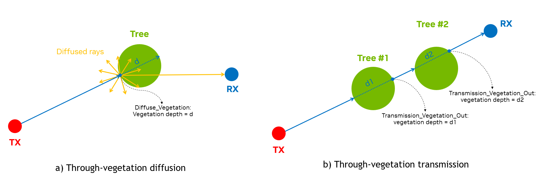
EM_INTERACT_TYPE
enum EM_INTERACT_TYPE : unsigned int {
    Emission = 0,
    Reflection = 1,
    Diffraction = 2,
    Diffuse = 3,
    Reception = 4,
    Transmission = 5,
    Diffuse_Vegetation = 6,
    Transmission_Vegetation_In = 7,
    Transmission_Vegetation_Out = 8,
    Reserved,
}
An enumeration of EM interaction types per ray.
EM_DIFFUSE_TYPE
enum EM_DIFFUSE_TYPE : unsigned int {
    Lambertian = 0,
    Directional = 1
}
An enumeration of EM diffuse type.
RayPath
struct RayPath {
    int tx_id{};
    int rx_id{};

    int tx_ij[2]{};
    int rx_ij[2]{};

    int rx_index{};

    EM_INTERACT_TYPE point_types[MAX_NUM_INTERACTIONS_WITH_TRANSMISSION+2]{};
    float3 points[MAX_NUM_INTERACTIONS_WITH_TRANSMISSION+2]{};

    int object_ids[MAX_NUM_INTERACTIONS_WITH_TRANSMISSION + 2]{};
    int prim_ids[MAX_NUM_INTERACTIONS_WITH_TRANSMISSION+2]{};

    float3 normals[MAX_NUM_INTERACTIONS_WITH_TRANSMISSION+2]{};
    float vegetation_depths[MAX_NUM_INTERACTIONS_WITH_TRANSMISSION + 2]{};

    int num_points{};

    d_complex cir_ampl[4]{};
    float cir_delay{};

    __host__ __device__ RayPath() {}
    __host__ __device__ RayPath(int *tx_ij, int *rx_ij, float3 *points,
                          EM_INTERACT_TYPE *point_types, int *object_ids,
                          int *prim_ids, float3 *normals, int tx_id,
                          int rx_id, int rx_index, int num_points);

    [[nodiscard]] bool operator==(const RayPath &other) const;
}
A struct storing geometry and EM data of a propagation path.
Member
Description
tx_id
ID of the RU (type
int)rx_id
ID of the UE (type
int)tx_ij
two-element array of indices (type
int,ifor horizontal index andjfor vertical index) of the antenna element within the RU panelrx_ij
two-element array of indices (type
int,ifor horizontal index andjfor vertical index) of the antenna element within the UE panelrx_index
index of the UE (type
int)point_types
an array of
EM_INTERACT_TYPEstoring the EM interaction types for points along the pathpoints
an array of
float3storing the (x, y, z) coordinates of interaction points, in the same unit as USD map*object_ids
an array of
intstoring the indices of the geometry object at the interaction points. The building object, if present, is indexed by 0, followed by the vehicular objects starting from 1. If the building is not present, the first vehicular object is indexed by 0 insteadprim_ids
an array of
intstoring the indices of the geometry primitive at the interaction points: the hit triangle index for a reflection, diffusion or transmission, the hit edge index for a diffraction, the hit tri-1s otherwise. The triangle index is local to the building mesh or the base (pre-trasform) scatterer meshnormals
an array of
float3storing the normals at the interaction pointsvegetation_depths
an array of
floatstoring the vegetation depth at the interaction points**num_points
number of interaction points from the RU to UE (type
int)cir_ampl
an array of four complex-valued elements storing the path CIR amplitude for four UE-RU polarization combinations***
cir_delay
propagation delay of the path (type
float), in seconds*The map unit is determined by
Meters Per Unitin the USD file. For example, a map is in meters ifMeters Per Unit = 1and in centimeters ifMeters Per Unit = 0.01.**For the transmission paths that go through each vegetation object, the
vegetation depthis zero atTransmission_Vegetation_Inpoint, and is equal to propagation path length betweenTransmission_Vegetation_InandTransmission_Vegetation_Outpoints at theTransmission_Vegetation_Outpoint. For the diffuse scattering paths from each vegetation object, thevegetation depthis stored at theDiffuse_Vegetationpoint, the first contact point of the ray from the TX on the vegetation object.***
cir_ampl[i*2 + j]is for the UE’s \(i\)-th polarization and RU’s \(j\)-th polarization, for \(i \in \left[0, 1\right]\) and \(j \in \left[0, 1\right]\).ANTENNA_TYPE
enum ANTENNA_TYPE : unsigned int {
    Isotropic = 0,
    Infinitesimal_dipole = 1,
    Halfwave_dipole = 2,
    Rec_microstrip_patch = 3,
    ThreeGPP_38901 = 4,
    Polarized_Isotropic = 5
}
An enumeration for the built-in antenna types currently supported by the EM solver.
AntennaPattern
struct AntennaPattern {
    int pattern_type{};
    std::vector<std::vector<d_complex>> ampls_theta{};
    std::vector<std::vector<d_complex>> ampls_phi{};

    [[nodiscard]] bool operator==(const AntennaPattern &other) const;
}
A struct storing a radiation pattern for a given antenna element, for either a built-in or a custom antenna type. The current version only supports patterns at a single frequency.
Member
Description
pattern_type
an integer indicating the radiation pattern type as defined in the
ANTENNA_TYPEenum (typeint)ampls_theta
a two-dimensional vector storing complex-valued amplitudes (type
d_complex) of the antenna radiated field along the theta direction, each inner vector stores the amplitudes for one frequencyampls_phi
a two-dimensional vector storing complex-valued amplitudes (type
d_complex) of the antenna radiated field along the phi direction, each inner vector stores the amplitudes for one frequencyFor built-in antenna types, the radiation fields are analytically calculated by the EM engine, and the
ampls_thetaandampls_phimember variables are ignored. For example, for anInfinitesimal_dipolepattern type, theAntennaPatternobject is:AntennaPattern pattern = {.pattern_type = 1, .ampls_theta = {}, .ampls_phi = {}};
AntennaPanel
struct AntennaPanel {
    std::string panel_name{};
    std::vector<std::string> antenna_names{};
    std::vector<int> antenna_pattern_indices{};
    std::vector<float> frequencies{};
    std::vector<float> thetas{};
    std::vector<float> phis{};
    double reference_freq{};
    bool dual_polarized{};
    int num_loc_antenna_horz{};
    int num_loc_antenna_vert{};
    double antenna_spacing_horz{};
    double antenna_spacing_vert{};
    double antenna_roll_angle_first_polz{};
    double antenna_roll_angle_second_polz{};

    [[nodiscard]] bool operator==(const AntennaPanel &other) const;
}
An struct storing information for a given antenna panel. The number of antenna elements in a panel is
num_loc_antenna_horz*num_loc_antenna_vert*num_polarizations.Member
Description
panel_name
name of the panel (type
string)antenna_names
a vector of names (type
string) of all antenna elements in the panelantenna_pattern_indices
a vector of indices (type
int) to thepatternsvector for the antenna elements in the panelfrequencies
a vector of frequencies (type
float) for the antenna radiation patterns of the antenna elements in the panel, in Hertzthetas
a vector storing elevation angles (type
float) of the radiation pattern for all antenna elements in the panel, in radians*phis
a vector storing azimuth angles (type
float) of the radiation pattern for all antenna elements in the panel, in radians*reference_freq
center frequency (type
double) of the panel, in Hertzdual_polarized
a
boolvariable to indicate if the panel antennas are dual- (true) or single- polarized (false)num_loc_antenna_horz
number of antenna element locations (type
int) in the planar array along a rownum_loc_antenna_vert
number of antenna element locations (type
int) in the planar array along a columnantenna_spacing_horz
horizontal antenna element spacing (type
double), in centimetersantenna_spacing_vert
vertical antenna element spacing (type
double), in centimetersantenna_roll_angle_first_polz
angular displacement of the antenna element realizing the first polarization (type
double), in radiansantenna_roll_angle_second_polz
angular displacement of the element realizing the second polarization (type
double), in radians*For custom antenna patterns, the ranges of thetas and phis need to follow the standard convetions: \([0, \pi]\) for thetas and \([0, 2\pi]\) for phis.
AntennaInfo
struct AntennaInfo {
    std::vector<AntennaPanel> panels{};
    std::vector<AntennaPattern> patterns{};

    [[nodiscard]] bool operator==(const AntennaInfo &other) const;
}
A struct encapsulating information of all antenna panels and antenna radiation patterns.
Member
Description
panels
vector of panels (type
AntennaPanel)patterns
vector of patterns (type
AntennaPattern)TXInfo
struct TXInfo {
    int tx_ID{};
    float3 tx_center{};
    Matrix4x4 Ttx{};

    std::vector<int> panel_id{};
    float height{};
    float mech_azimuth_deg{};
    float mech_tilt_deg{};

    float carrier_freq{};
    float carrier_bandwidth{};
    float subcarrier_spacing{};
    int fft_size{};
    float radiated_power{};
    std::vector<std::string> antenna_names{};
    std::vector<int> antenna_pattern_indices{};
    bool dual_polarized_antenna{};
    std::vector<float3> antenna_rotation_angles{};
    int num_loc_antenna_horz{};
    int num_loc_antenna_vert{};
    std::vector<float3> loc_antenna{};
    std::vector<std::pair<int, int>> ij_antenna{};
}
An struct storing RU information.
Member
Description
tx_ID
ID of the RU (type
int)tx_center
(x , y, z) coordinates of the RU center (type
float3), in the same unit as USD mapTtx
a
Matrix4x4transformation matrix for the RU combining translation and rotation, in the same unit as USD mappanel_id
a vector of indices (type
int) identifying the panels used by the RU; currently only size 1 is supportedheight
height (type
float) calculated from RU base to the RU center, in centimetersmech_azimuth_deg
mechanical azimuth (type
float) of the RU, in degreesmech_tilt_deg
mechanical tilt (type
float) of the RU, in degreescarrier_freq
carrier frequency (type
float) of the RU, in Hertzsubcarrier_spacing
sub-carrier spacing (type
float), in Hertzfft_size
FFT size (type
int) used for wideband CFR calculationradiated_power
radiated power (type
float) of the RU, in Wattsantenna_names
a vector of names (type
string) of all antenna elements in the RU panelantenna_pattern_indices
a vector of indices (type
int) to thepatternsvector for the antenna elements in the RU paneldual_polarized_antenna
a
boolvariable to indicate if the RU antenna panel is composed by dual- (true) or single- polarized (false) elementsantenna_rotation_angles
a vector of triplets storing rotation angles (type
float3) of the antennas: the first triplet is for the first polarization, and in case of dual-polarized antennas, the second triplet is for the second polarizationnum_loc_antenna_horz
number of antenna element locations (type
int) in the horizontal direction within the RU antenna panelnum_loc_antenna_vert
number of antenna element locations (type
int) in the vertical direction within the RU antenna panelloc_antenna
vector of (x, y, z) of antenna positions within the RU antenna panel (type
float3), in the same unit as USD map*ij_antenna
a vector of pairs of indices (type
int) storing horizontal and vertical indices of the antenna elements in the RU antenna panelNote: The antenna locations and the
(i, j)antenna indices in theTXInfoare order-consistent: e.g. the element at location indexed by(i, j)with polarizationp, isantenna_names[i*num_loc_antenna_vert*num_polarizations + j*num_polarizations + p - 1], wherenum_polarizationsis 1 for single-polarized panels and 2 for dual-polarized panels. In addition,(i, j) = (0, 0)indicates the bottom-left antenna location in the antenna array. These conventions are also used forRXInfostruct below. It is worth noticing that, in the graphical interface, the top and the bottom of the array are inverted, i.e., what is at the top in the graphical interface is considered at the bottom in EM solver.RXInfo
struct RXInfo {
    int rx_ID{};
    float3 rx_center{};
    Matrix4x4 Trx{};

    std::vector<int> panel_id{};
    float radiated_power{};
    std::vector<std::string> antenna_names{};
    std::vector<int> antenna_pattern_indices{};
    bool dual_polarized_antenna{};
    std::vector<float3> antenna_rotation_angles{};
    int num_loc_antenna_horz{};
    int num_loc_antenna_vert{};
    std::vector<float3> loc_antenna{};
    std::vector<std::pair<int, int>> ij_antenna{};
}
An struct storing UE information.
Member
Description
rx_ID
ID of the UE (type
int)rx_center
(x , y, z) coordinates of the UE center (type
float3), in the same unit as USD mapTrx
a
Matrix4x4transformation matrix for the UE combining translation and rotation, in the same unit as USD mappanel_id
a vector of indices (type
int) identifying the panels used by the UE; currently only size 1 is supportedradiated_power
radiated power (type
float) of the UE, in Wattsantenna_names
a vector of names (type
string) of all antenna elements in the UE panelantenna_pattern_indices
a vector of indices (type
int) to thepatternsvector for the antenna elements in the UE paneldual_polarized_antenna
a
boolvariable to indicate if the UE antenna panel is composed by dual- (true) or single- polarized (false) elementsantenna_rotation_angles
a vector of triplets storing rotation angles (type
float3) of the antennas: the first triplet is for the first polarization, and in case of dual-polarized antennas, the second triplet is for the second polarizationnum_loc_antenna_horz
number of antenna element locations (type
int) in the horizontal direction within the UE antenna panelnum_loc_antenna_vert
number of antenna element locations (type
int) in the vertical direction within the UE antenna panelloc_antenna
vector of (x, y, z) of antenna positions within the RU antenna panel (type
float3), in the same unit as USD mapij_antenna
a vector of pairs of indices (type
int) storing horizontal and vertical indices of the antenna elements in the UE antenna panelMesh
struct Mesh {
    std::vector<float3> mesh_vertices{};
    std::vector<int> triangle_material_ids{};
    bool is_diffusion{};
    bool is_diffraction{};
    bool is_transmission{};
    float diffuse_dS_sqm = 1.0;

    [[nodiscard]] bool operator==(const Mesh &other) const;
};
A struct storing information of a triangular mesh in the scene.
Member
Description
mesh_vertices
a vector of vertices (type
float3) of the triangular mesh*, in the same unit as USD maptriangle_material_ids
a vector of material indices (type
int) of the mesh’s trianglesis_diffusion
flag (type
boolean) to indicate if the mesh is enabled for diffuse (True) or not (False)is_diffraction
flag (type
boolean) to indicate if the mesh is enabled for diffraction (True) or not (False)is_transmission
flag (type
boolean) to indicate if the mesh is enabled for transmission (True) or not (False)diffuse_dS_sqm
(type
float) the area of the diffuse surface element in square meterNotes: The vertices are grouped in tuples of 3 elements for the building triangles, e.g., vertices {[0], [1], [2]} for the first triangle, vertices {[3], [4], [5]} for the second triangles and so on. For each triangle, the vertex winding order is counter-clockwise so that its front face normal points outward for the building meshes and upward for the ground meshes.
SCATTERER_TYPE
enum SCATTERER_TYPE : int { Vehicle = 0 };
An enumeration for the scatterer type.
ScattererInfo
struct ScattererInfo {
int id{};
SCATTERER_TYPE type{};
int mesh_ind{};
Matrix4x4 transform{};

[[nodiscard]] bool operator==(const ScattererInfo &other) const;
};
A struct storing information of a scatterer in the scene.
Member
Description
id
index of the scatterer (type
int)SCATTERER_TYPE
type of the scatterer (type
SCATTERER_TYPE)mesh_id
index of the base (pre-transform) mesh in the the array
geometry_info.scatterer_meshused for the scatterer (typeint)transform
transformation matrix for the scatterer combining scaling, translation and rotation, in the same unit as USD map (type
Matrix4x4)VEGETATION_TYPE
enum VEGETATION_TYPE : int {
    Street_Tree = 0,
    // Add more here
};
An enumeration for the vegetation type.
VegetationInfo
struct VegetationInfo {
    int id{};
    VEGETATION_TYPE type{};
    int mesh_ind{}; // index to the array geometry_info.vegetation_mesh
    Matrix4x4 transform{};

    [[nodiscard]] bool operator==(const VegetationInfo &other) const;
};
A struct storing information of a vegetation in the scene.
Member
Description
id
index of the vegetation (type
int)VEGETATION_TYPE
type of the vegetation (type
EM_VEGETATION_MODEL)mesh_id
index of the base (pre-transform) mesh in the the array
geometry_info.vegetation_meshused for the vegetation (typeint)transform
transformation matrix for the scatterer combining scaling, translation and rotation, in the same unit as USD map (type
Matrix4x4)GeometryInfo
struct GeometryInfo {
    std::vector<Mesh> building_mesh{};
    std::vector<Mesh> terrain_mesh{};
    std::vector<Mesh> scatterer_mesh{};
    std::vector<ScattererInfo> scatterer_info{};
    std::vector<Mesh> vegetation_mesh{};
    std::vector<VegetationInfo> vegetation_info{};
    std::unordered_map<std::string, std::pair<int,EMMaterial>> material_dict{};
    std::unordered_map<std::string, std::pair<int, EMVegetationMaterial_ITUR>>
        vegetation_material_ITUR_dict{};
    float meters_per_unit = 0.01f;

    [[nodiscard]] bool operator==(const GeometryInfo &other) const;
};
A struct storing information for the geometries in the scene.
Member
Description
building_mesh
a vector of building meshes (type
Mesh) in the sceneterrain_mesh
a vector of terrain meshes (type
Mesh) in the scenescatterer_mesh
a vector of scatterer meshes (type
Mesh), each holds the base (pre-transform) mesh and related metadata for each type of scatterer in the scenescatterer_info
a vector of
ScattererInfostructs storing the information of the scatterers in the scenevegetation_mesh
a vector of vegetation meshes (type
Mesh), each holds the base (pre-transform) mesh and related metadata for each type of vegetation in the scenevegetation_info
a vector of
VegeationInfostructs storing the information of the vegetations in the scenematerial_dict
an unordered map for the material dictionary storing all materials in the scene: key is the material name (type
string) and value is a pair of<int, EMMaterial>vegetation_material_ITUR_dict
an unordered map for the vegetation material dictionary storing all materials in the scene: key is the material name (type
string) and value is a pair of<int, EMVegetationMaterial_ITUR>meters_per_unit
a constant value of the amount of meters in the spatial units of the meshes (type
float), default value is 0.010.01RTConfig
struct RTConfig {
    int num_rays_in_thousands{};
    int max_num_bounces{};
    float rx_sphere_radius_cm{};
    EM_DIFFUSE_TYPE em_diffuse_type{};
    bool use_only_first_antenna_pair{};
    bool write_cfr_results{true};
    bool write_tau_mins{};
    bool simulate_ran{};
    int max_num_paths_per_ant_pair{};
    EM_VEGETATION_MODEL em_vegetation_model{};
    bool write_cir_results{};

    [[nodiscard]] bool operator==(const RTConfig &other) const;
}
A struct storing the configuration of the raytracing parameters.
Member
Description
num_rays_in_thousands
number of emitted rays in thousands (type
int)max_num_bounces
maximum number of scattering events for each emitted ray (type
int)rx_sphere_radius_cm
reception sphere radius (type
float), in centimetersdiffuse_type
diffuse type to indicate the diffuse scattering model (type
EM_DIFFUSE_TYPE): Lambertian = 0, Directional = 1use_only_first_antenna_pair
a
boolvariable, when set totrueonly the results for the first RU-UE antenna pair are returned fromrunEMSolver()write_cfr_results
a
boolvariable, when set totrue,runEMSolver()returns the channel frequency response results stored on device buffersd_all_cfr_results. Default value is set toTruewrite_tau_mins
a
boolvariable, when set totrue,runEMSolver()returns the minimum propagation delays stored on device buffersd_all_tau_minssimulate_ran
a
boolvariable, when set totruethe full RAN simulation is enabledmax_num_paths_per_ant_pair
the maximum number of strongest paths retained per RU-UE antenna pair (type
int)em_vegetation_model
enumeration for the vegetation attenuation model (type
EM_VEGETATION_MODEL). Currently only ITU_R 388-10 model [7] is supportedwrite_cir_results
a
boolvariable, when set totrue,runEMSolver()returns the CIR values and delays stored on the device bufferscir_valuesandcir_delaysinCIRResultstructs, respectively
Compute mutual coupling patterns#
compute_mutual_coupling_patterns()
std::vector<emsolver::AntennaPattern> compute_mutual_coupling_patterns(const emsolver::AntennaPanel &panel);
Compute antenna patterns including the effect of mutual coupling.
Supported CUDA architectures#
supported_cuda_architectures()
std::vector<uint32_t> supported_cuda_architectures();
Returns list of supported cuda architectures based on emsolver library compilation, e.g. [80, 86, 89, 90].
Class AerialEMSolver#
AerialEMSolver()
AerialEMSolver(const std::vector<TXInfo>& tx_info,
               const std::vector<RXInfo>& rx_info,
               const AntennaInfo& antenna_info,
               const GeometryInfo& geometry_info,
               const RTConfig& rt_cfg,
               cudaStream_t ext_stream);
Constructor for the AerialEMSolver object.
In/out
Parameter
Description
[in]
tx_info
a vector of
TXInfostructs storing the information of the RUs[in]
rx_info
a vector of
RXInfostructs storing the information of the UEs[in]
antenna_info
AntennaInfostruct storing the information of all antenna panels and antenna radiation patterns[in]
geometry_info
GeometryInfostruct storing the information of the scene geometry and materials[in]
rt_cfg
RTConfigstruct storing the ray tracing configurations[in]
ext_stream
CUDA stream index (type
cudaStream_t)~AerialEMSolver()
~AerialEMSolver()
Destructor for the AerialEMSolver object.
allocateDeviceMemForResults()
int32_t allocateDeviceMemForResults(const std::vector<TXInfo>& tx_info,
                                    const std::vector<RXInfo>& rx_info,
                                    const std::vector<uint32_t>& tx_indices,
                                    const std::vector<std::vector<uint32_t>>& rx_indices,
                                    const RTConfig& rt_cfg,
                                    const int symbols_per_slot,
                                    std::vector<d_complex*>& d_all_cfr_results,
                                    std::vector<float*>& d_all_tau_mins,
                                    std::vector<CIRResult> &d_all_cir_results);
Allocation of device (GPU) memory to store the results of the EM engine.
In/out
Parameter
Description
[in]
tx_info
a vector of
TXInfostructs storing the information of all the RUs[in]
rx_info
a vector of
RXInfostructs storing the information of all the UEs[in]
tx_indices
a vector of indices (type
uint32_t) for the RUs whose results need to be computed[in]
rx_indices
a vector of vectors of indices (type
uint32_t) of selected UEs for each RUs whose results need to be computed[in]
rt_cfg
RTConfigstruct storing the raytracing configuration[in]
symbols_per_slot
number of symbols (type
int) in one slot (either 1 or 14)[out]
d_all_cfr_results
a vector of device pointers (type
d_complex), each pointing to memory address holding the CFRs for the UEs associated to a given RU. The content of the vector follows the content oftx_indices. The allocation is realized whenwrite_cfr_resultsin thert_configistrue[out]
d_all_tau_mins
a vector of device pointers (type
float), each pointing to memory address holding the minimum propagation delay for the UEs associated to a given RU. The content of the vector follows the content oftx_indices. The allocation is realized whenwrite_tau_minsin thert_configistrue[out]
d_all_cir_results
a vector of
CIRResultstructs storing the CIR results. The content of the vector follows the content oftx_indices. The allocation is realized only whenwrite_cir_resultsin thert_configistrueAll CFR results for the \(i\)-th RU, i.e.,
d_all_cfr_results_i = d_all_cfr_results[i], are stored in the device memory as a flattened representation of multidimensional array whose indices, in order, are<ue_idx>, <symbol_idx>, <freq_idx>, <ue_ant_idx>, <ue_ant_pol_idx>, <ru_ant_idx>, <ru_ant_pol_idx>.For example, the first 6 elements of
d_all_cfr_results_i, with the \(i\)-the RU being equipped with dual-polarized antennas and all associated UEs also having dual-polarized antennas, are: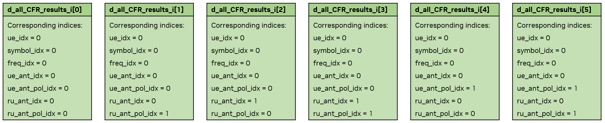
For the minimum delay results, there is one minimum delay for all RU-UE antenna pairs (i.e., one value for one RU-UE pair, and
d_all_cfr_results[i]holds the minimum delays from \(i\)-th RU to its associated UEs).Similar device memory arrangements are done for
cir_valuesandcir_delaysind_all_cir_results[i](typeCIRResult) for the \(i\)-th RU.runEMSolver()
int32_t runEMSolver(const unsigned int time_idx,
                    const std::vector<TXInfo>& tx_info,
                    const std::vector<RXInfo>& rx_info,
                    const AntennaInfo& antenna_info,
                    const GeometryInfo &geometry_info,
                    const std::vector<uint32_t>& tx_indices,
                    std::vector<std::vector<uint32_t>>& rx_indices,
                    const RTConfig& rt_cfg,
                    const int symbol_idx,
                    const int symbols_per_slot,
                    std::vector<RayPath>& all_ray_path_results,
                    std::vector<d_complex*>& d_all_cfr_results,
                    std::vector<float*>& d_all_tau_mins,
                    std::vector<CIRResult> &d_all_cir_results);
Launch the EM engine.
In/out
Parameter
Description
[in]
time_idx
time index (type
unsigned int) in the simulation[in]
tx_info
a vector of
TXInfostructs storing the information of all the RUs[in]
rx_info
a vector of
RXInfostructs storing the information of all the UEs[in]
antenna_info
AntennaInfostruct storing the information of all antenna panels and antenna radiation patterns[in]
geometry_info
GeometryInfostruct storing the information of the scene geometry and materials[in]
tx_indices
a vector of indices (type
uint32_t) for the RUs whose results need to be computed[in]
rx_indices
a vector of vectors of indices (type
uint32_t) of selected UEs for each RUs whose results need to be computed[in]
rt_cfg
RTConfigstruct storing the ray tracing configurations[in]
symbol_idx
symbol index (type
int) within a slot[in]
symbols_per_slot
number of symbols (type
int) in one slot (either 1 or 14)[in]
all_ray_path_results
a vector of
RayPathstructs storing all propagation results from all selected RUs to their associated UEs[out]
d_all_cfr_results
a vector of device pointers (type
d_complex), each pointing to memory address holding the CFRs for the UEs associated to a given RU. The content of the vector follows the content oftx_indices. The storing is realized whenwrite_cfr_resultsin thert_configistrue[out]
d_all_tau_mins
a vector of device pointers (type
float), each pointing to memory address holding the minimum propagation delay for the UEs associated to a given RU. The content of the vector follows the content oftx_indices. The storing is realized whenwrite_tau_minsin thert_configistrue[out]
d_all_cir_results
a vector of
CIRResultstructs storing the CIR results. The content of the vector follows the content oftx_indices. The storing is realized only whenwrite_cir_resultsin thert_configistruecopyResultsFromDeviceToHost()
int32_t copyResultsFromDeviceToHost(const std::vector<uint32_t>& tx_indices,
                                    const std::vector<std::vector<uint32_t>>& rx_indices,
                                    const RTConfig& rt_cfg,
                                    const int symbols_per_slot,
                                    const std::vector<d_complex*>& d_all_cfr_results,
                                    std::vector<std::vector<d_complex>>* all_cfr_results);
Copy the results of the EM engine from device to host.
In/out
Parameter
Description
[in]
tx_indices
a vector of indices (type
uint32_t) for the RUs whose results need to be computed[in]
rx_indices
a vector of vectors of indices (type
uint32_t) of selected UEs for each RUs whose results need to be computed[in]
rt_cfg
RTConfigstruct storing the ray tracing configurations[in]
symbols_per_slot
number of symbols (type
int) in one slot (either 1 or 14)[in]
d_all_cfr_results
a vector of device pointers (type
d_complex), each pointing to memory address holding the CFRs for the UEs associated to a given RU. The content of the vector follows the content oftx_indices[out]
all_cfr_results
a pointer to a host-side vector of vectors for the CFR results, with the inner vector holding the CFRs from one RU to its associated UEs and the outer vector following
tx_indicesdeAllocateDeviceMemForResults()
int32_t deAllocateDeviceMemForResults(const RTConfig& rt_cfg,
                                      std::vector<d_complex*>& d_all_cfr_results,
                                      std::vector<float*>& d_all_tau_mins,
                                      std::vector<CIRResult> &d_all_cir_results);
Deallocate device memory previously used for the EM engine results.
In/out
Parameter
Description
[in]
rt_cfg
RTConfigstruct storing the ray tracing configurations[in]
d_all_cfr_results
a vector of device pointers (type
d_complex): each of them pointing to a device memory that holds complex-valued amplitude of the CFRs from one RU to its associated UEs. The size of the vector is equal to size of the tx_indices[in]
d_all_tau_mins
a vector of device pointers (type
float), each pointing to memory address holding the minimum propagation delay for the UEs associated to a given RU. The content of the vector follows the content oftx_indices[in]
d_all_cir_results
a vector of
CIRResultstructs storing the CIR results. The content of the vector follows the content oftx_indices.
Error handling#
The EM engine has built-in error handling. The function where the error or invalid condition occurs is recorded and error messages are propagated to both the local and console and the Console tab in the graphical interface.
EMLogLevel
enum class EMLogLevel {ERROR=0, NOTIFY=1, WARNING=2, INFO=3, DEBUG=4, VERBOSE=5}
An enumeration for the level of logging.
EMLogCallback
EMLogCallback = std::function<void(EMLogLevel, const std::string&)>;
Callback function prototype.
registerLogCallback()
int32_t registerLogCallback(EMLogCallback func);
Function to register a callback function (type
EMLogCallback) for error handling.deregisterLogCallback()
int32_t deregisterLogCallback();
Function to deregister the currently registered callback function.
Source code and dev. container#
The run_aodt_sim_devel.sh script mounts the source code into the container so that edits and builds within the development container persist on the host disk.
Before running the code inside the dev. container, the aodt_sim container started by the install script must be stopped.
cd $HOME/aodt_1.3.1/backend
docker compose stop worker
Once the container is stopped, we can follow these instructions to build the aodt_sim executable:
cd aodt_sim
# Set to desired GPU number. E.g., 0 to use GPU device 0 from inside the container.
GPU=0 ./container/run_aodt_sim_devel.sh
docker exec -it c_aodt_sim_$USER /bin/bash

# Inside the development container
cmake -Bbuild -GNinja -DCMAKE_CUDA_ARCHITECTURES="80;86;89;90" -DNVTX_ENABLED=OFF -DCMAKE_BUILD_TYPE=RelWithDebInfo
cmake --build build

export PYTHONPATH=$PYTHONPATH:/opt/nvidia/packman/lib/python:/opt/nvidia/aodt_sim/build/src_py/aodt

# Test the build
cd src_py
OMNI_USER=omniverse OMNI_PASS=aerial_123456 python -u -m aodt.app.sim --nats_server_url=nats-server:4222 --nats_subject=aerial --log debug
The example above assumes that the installation scripts have been executed. As part of the installation, lines have been added to the /etc/hosts file that resolves the IP addresses of omniverse-server and clickhouse; both will resolve to the IP address of the backend server.
Notable bug fixes and improvements in release 1.3.1#
Improved Edge Detection#
Two main improvements to diffraction points:
Improved detection of diffraction edges for rays passing very close to the edge.
Fixed cases where a ray could miss an edge and continue through a building as if the building were transparent. In such scenarios, the next edge would be detected, but the ray would approach from the interior, resulting in physically inconsistent coefficients.
Fixed normal ambiguity#
The reflection and transmission coefficients are functions of the direction of the normal to the impinged surface. In previous releases, when transmission is enabled, the indoor normals can point outwards, thus creating wrong results. From release 1.3.0, the normals for such reflections are calculated correctly.
Fixed UE orientation#
UE orientation in the second sample was often inexact due to a copy from the first sample. From release 1.3.0, the orientation is always correct and reflecting the movement of the UE.
Fixed frequency-domain correlation#
When rays hit a point at the border between two objects of different materials, the frequency response of the channel had the wrong frequency correlation function. This is now fixed.
Bug reporting#
When reporting bugs to NVIDIA, the following information ensures that the error can be reproduced and correctly addressed.
The Aerial Omniverse Digital Twin release version
The system configuration where the bug occurs
A detailed description of the issue (errors or unexpected outcomes) and of the steps to reproduce it.
Bugs can be reported via the NVIDIA Aerial Developer Forum.