Installation Guide
Integrating and deploying Aerial Research Cloud network for Advanced 5G and 6G.
Integrating and deploying Aerial Research Cloud for Advanced 5G and 6G research can be described in the following steps:
Chapter 1: Procure all the required hardware based on the published BOM in this document
Chapter 2: Configure the network hardware
Chapter 3: Use the SDK Manager to install
Chapter 4: Install the software to match the published release manifest
Chapter 5: Validate the setup by successfully running bi-directional UDP traffic as described
The rest of this document provides the step-by-step description to enable early research testbed staging, integrating, configuration, and validating network go-live with IP traffic.
ARC Software Release Manifest
| Component | Version |
| Aerial SDK (ASDK) PHY | 23-2 |
| OAI gNB | OAI_Aerial_v2.0 |
| OAI CN | OAI_Aerial_v2.0 |
Procure all the hardware listed in the BOM as follows:
5G Infrastructure Blueprint HW BOM
Unless specific solution architecture differs based on use case, all components are required in a unit of 1.
55G Infra Component |
HW Manifest |
|---|---|
| Aerial gNB | Gigabyte Edge E251-U70 Server x 1 with CPU Intel Xeon Gold 6240R, 2.4GHz, 24C48T, Memory 96GB DDR4, Storage 480GB LiteOn SSD x1. GPU GA100 x1, NIC x1 MLX CX6-DX MCX623106AE-CDAT |
| CN | Dell PowerEdge R750 Server |
| FrountHaul(FH) Switch only pick one | Dell PowerSwitch S5248F-ON |
| Fibrolan Falcon RX | |
| GrandMaster(GM) | QULSAR Qg 2 Multi-Sync Gateway |
| O-RUs supported | ORU : Configuration : Freq Band |
| Foxconn : 4T4R : 3.7GHz - 3.8GHz | |
| RPQN-7801E : : (indoors) | |
| UEs supported | UE: Module Sierra Wireless EM9191 NR 5G Modem Config: SU-MIMO 2DL, 1UL |
| UE: Quectel RM500Q-GL UE Config: SU-MIMO 2DL, 1UL | |
| UE: 5G USB Dongle https://www.routerdistributor.com/shop/4g-5g-dongles/apal-5g-usb-dongle/. Config: SU-MIMO 2DL, 1UL | |
| UE: iPhone 14 Pro, with iOS version 16.6.1, Model number MPXV3HX/A | |
| Cables | Dell C2G 1m LC-LC 50/125 Duplex Multimode OM4 Fiber Cable Aqua 3ft Optical patch cable |
| NVIDIA MCP1600-C001E30N DAC Cable Ethernet 100GbE QSFP28 1m | |
| Beyondtech 5m (16ft) LC UPC to LC UPC Duplex OM3 Multimode PVC (OFNR) 2.0mm Fiber Optic Patch Cable | |
| CableCreation 3ft Cat5/Cat6 Ethernet Cables | |
| PDUs | Tripp Lite 1.4kW Single-Phase Monitored PDU with LX Platform Interface, 120V Outlets (8 5-15R), 5-15P, 12ft Cord, 1U Rack-Mount, TAA |
| Transceivers | Finisar SFP-to-RJ45 Transceiver |
| Intel Ethernet SFP+SR Optics | |
| Dell SFP28-25G-SR Transceiver | |
| Ethernet Switch | Netgear ProSafe Plus JGS524E Rackmount |
| iPerf Laptop | Connected to the switch (10G ethernet) |
To procure all the hardware items in the blueprint BOM, contact the Aerial Research Cloud team at arc@nvidia.com. In the Email, include your full name, company name, preferred Email contact, and country/region.
Refer to the tutorials for help with these installation steps.
Configuration Steps
Setup the GrandMaster
Setup the switch
Setup PTP
Setup Foxconn O-RU
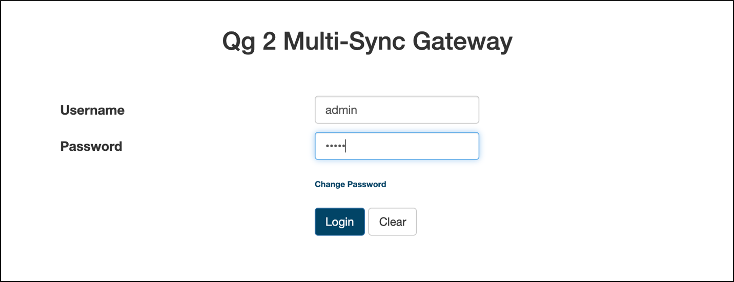
Chapter 2.1 Setup the Qulsar GrandMaster
Step 1.
Follow the Qulsar User Guide to setup the MGMT connection.
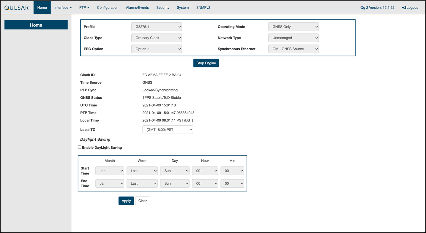
Step 2.
Set the operating mode to GNSS Only, and other fields as such, then run Start Engine.
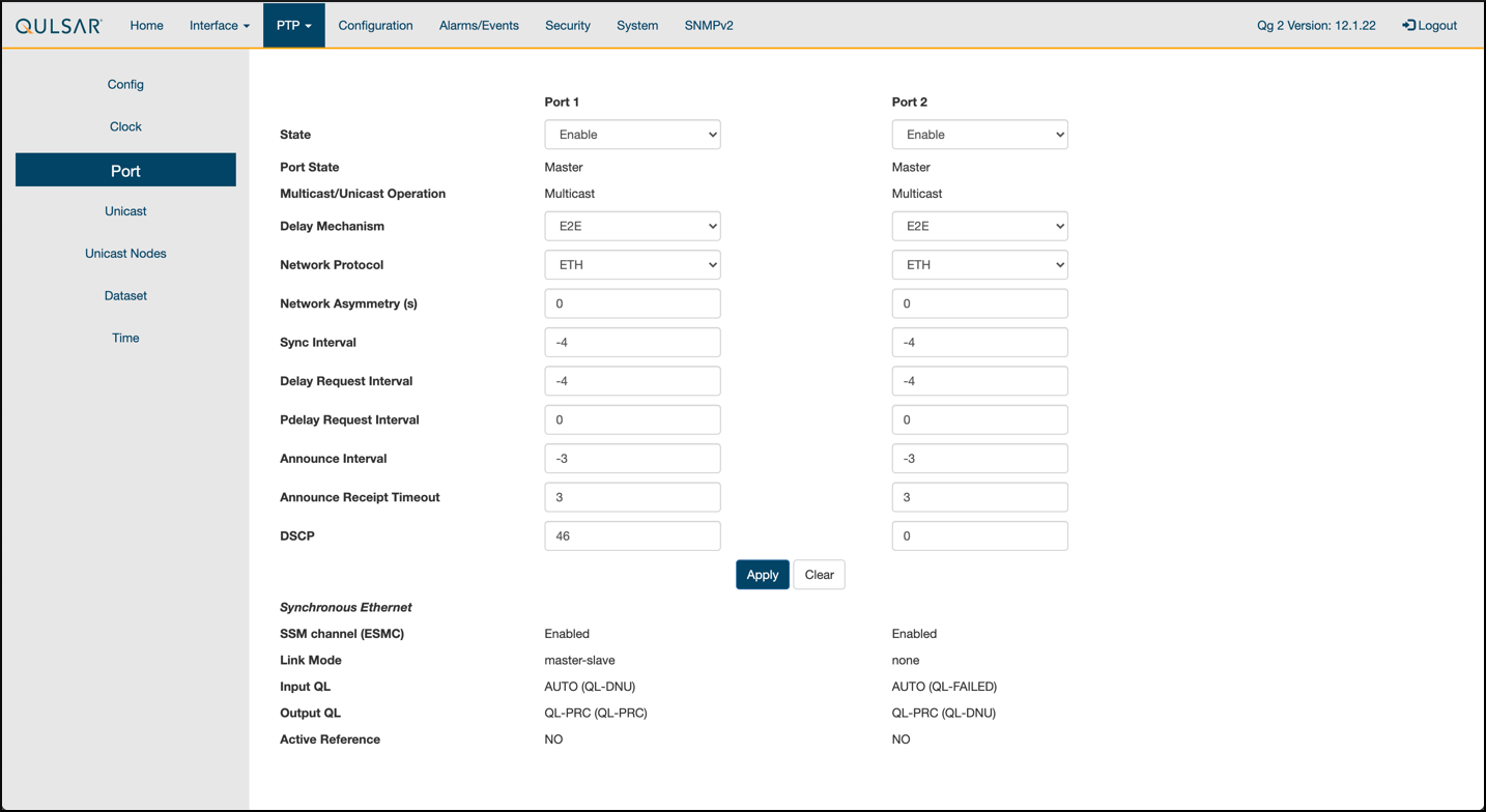
Step 3.
Enable the ports on the GrandMaster with the 8275.1 Profile configurations.
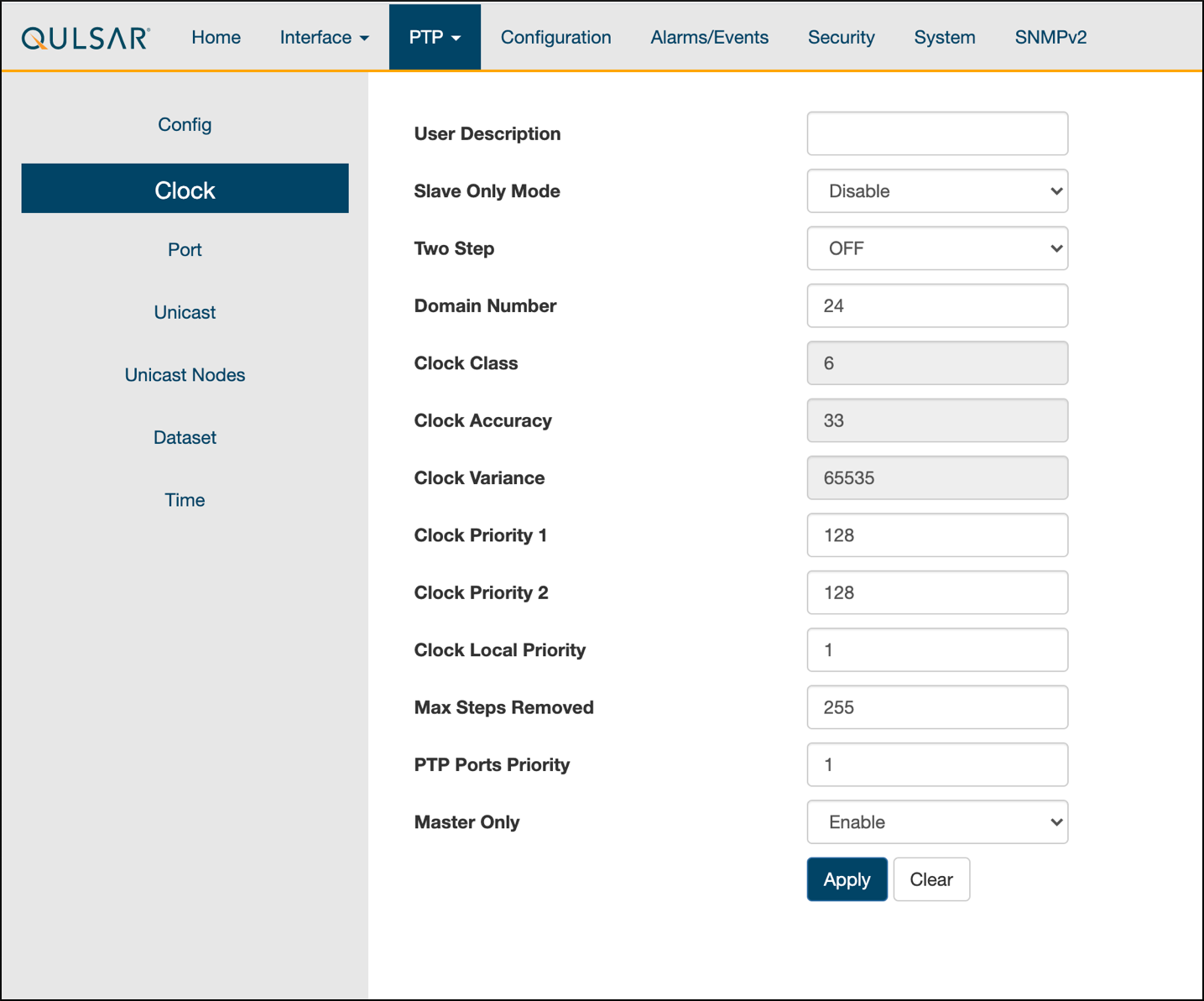
Step 4.
Configure the clock configs as such:
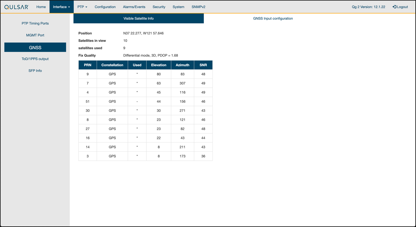
Step 5.
GPS configuration values are unchanged from the default settings of QG2.
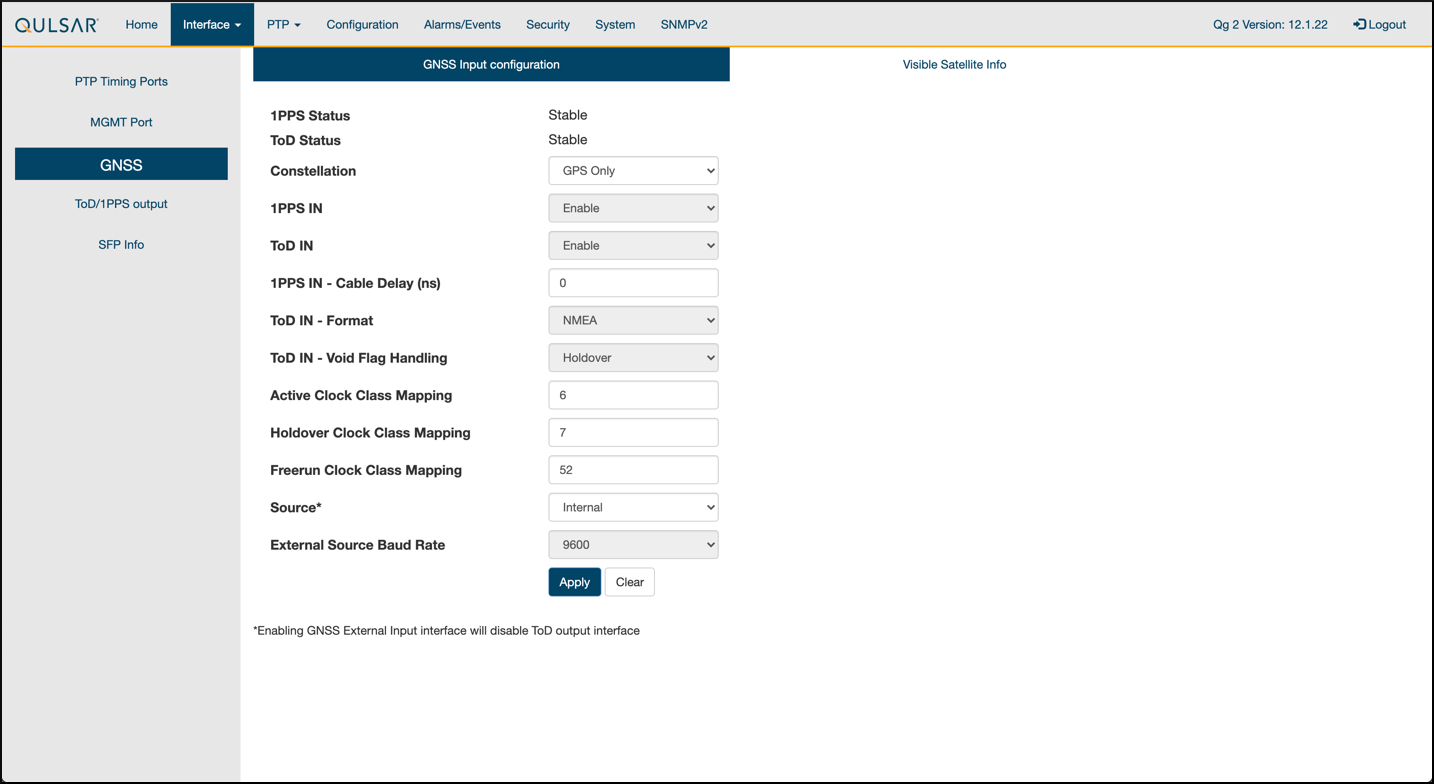
Step 6.
Verify that the GPS Signal reaches the GrandMaster.
Chapter 2.2 Switch Setup
Chapter 2.2.1 Dell Switch
In the following example on vlan 2 the:
RUs are on ports 1 and 7
GrandMaster is on port 5
CN is on ports 11 and 12
gNB ports are connected to ports 49 and 51
Set up MGMT access to the switch, in this case 172.168.20.67.
            OS10# configure terminal
OS10(config)#
interface mgmt1/1/1
no shutdown
no ip address dhcp
ip address 172.16.204.67/22
exit
You should now be able to ssh to admin@172.168.204.67.
Set the speed to 10G for port groups 1 and 2:
            OS10(config)#
port-group 1/1/1
mode Eth 10g-4x
exit
port-group 1/1/2
mode Eth 10g-4x
exit
Enable PTP on the switch:
            OS10# configure terminal
OS10(config)#
ptp clock boundary profile g8275.1
ptp domain 24
ptp system-time enable
!
Configure the GrandMaster port:
            OS10(config)#
interface ethernet 1/1/5:1
no shutdown
no switchport
ip address 169.254.2.1/24
flowcontrol receive off
ptp delay-req-min-interval -4
ptp enable
ptp sync-interval -4
ptp transport layer2
exit
After some time, the following prints:
            <165>1 2023-05-09T07:49:22.625584+00:00 OS10 dn_alm 1021 - - Node.1-Unit.1:PRI [event], Dell EMC (OS10) %PTP_SYSTEM_TIME_NOT_SET: System time is not set. System time will be set when the clock is.
<165>1 2023-05-09T07:51:22.312557+00:00 OS10 dn_alm 1021 - - Node.1-Unit.1:PRI [event], Dell EMC (OS10) %PTP_CLOCK_PHASE_LOCKED: Clock servo is phase locked.
<165>1 2023-05-09T07:51:22.313081+00:00 OS10 dn_alm 1021 - - Node.1-Unit.1:PRI [event], Dell EMC (OS10) %PTP_SYSTEM_TIME_UPDATE_STARTED: System time update service is started. Update interval: 60 minutes.
<165>1 2023-05-09T07:51:59.334346+00:00 OS10 dn_alm 1021 - - Node.1-Unit.1:PRI [event], Dell EMC (OS10) %ALM_CLOCK_UPDATE: Clock changed MESSAGE=apt-daily.timer: Adding 6h 36min 18.719270s random time.
<165>1 2023-05-09T07:57:27.254181+00:00 OS10 dn_alm 1021 - - Node.1-Unit.1:PRI [event], Dell EMC (OS10) %ALM_CLOCK_UPDATE: Clock changed MESSAGE=apt-daily.timer: Adding 4h 31mi
Confgure Fronthaul Network Configuration by creating a VLAN.
Create vlan 2:
            OS10(config)#
interface vlan 2
OS10(conf-if-vl-2)#
<165>1 2023-03-16T16:51:36.458730+00:00 OS10 dn_alm 813 - - Node.1-Unit.1:PRI [event], Dell EMC (OS10) %IFM_ASTATE_UP: Interface admin state up :vlan2

OS10(conf-if-vl-2)# show configuration
!
interface vlan2
no shutdown
OS10(conf-if-vl-2)# exit
Configure RU, gNB, CN, and MEC ports Intefaces which are configured to be slower than their maximum speed have a :1 appended to their name. This applies to ports in port groups 1 and 2.
            no shutdown
switchport mode trunk
switchport trunk allowed vlan 2
mtu 8192
flowcontrol receive off
ptp enable
ptp transport layer2
exit
Check the PTP status:
            OS10# show ptp | no-more
PTP Clock : Boundary
Clock Identity : b0:4f:13:ff:ff:46:63:5f
GrandMaster Clock Identity : fc:af:6a:ff:fe:02:bc:8d
Clock Mode : One-step
Clock Quality
Class : 135
Accuracy : <=100ns
Offset Log Scaled Variance : 65535
Domain : 24
Priority1 : 128
Priority2 : 128
Profile : G8275-1(Local-Priority:-128)
Steps Removed : 1
Mean Path Delay(ns) : 637
Offset From Master(ns) : 1
Number of Ports : 8
----------------------------------------------------------------------------
Interface State Port Identity
----------------------------------------------------------------------------
Ethernet1/1/1:1 Master b0:4f:13:ff:ff:46:63:5f:1
Ethernet1/1/3:1 Master b0:4f:13:ff:ff:46:63:5f:3
Ethernet1/1/5:1 Slave b0:4f:13:ff:ff:46:63:5f:5
Ethernet1/1/7:1 Master b0:4f:13:ff:ff:46:63:5f:8
Ethernet1/1/11 Master b0:4f:13:ff:ff:46:63:5f:4
Ethernet1/1/49 Master b0:4f:13:ff:ff:46:63:5f:9
Ethernet1/1/51 Master b0:4f:13:ff:ff:46:63:5f:10
Ethernet1/1/54 Master b0:4f:13:ff:ff:46:63:5f:2
----------------------------------------------------------------------------
Number of slave ports :1
Number of master ports :7
Save switch configuration
copy running-configuration startup-configuration
Chapter 2.2.2 Fibrolan Falcon RX Setup
Although the Fibrolan switch has not been qualified in NVIDIA lab, OAI labs incorporate the following configuration and switch for interoperability.
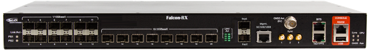
To get started follow the Fibrolan Getting Started Guide.
In our setup the Qulsar GrandMaster is connected to port 4, the Aerial SDK to port 17, and the Foxconn O-RU to port 16 (C/U plane) and port 15 (S/M plane). You can ignore all other ports in the figures[A][B] below.
VLAN setup
The following assumes that the VLAN tag for both the control plane and the user plane of the O-RAN CU plane is 2. VLAN 80 is used for everything else.

Figure A - Vlan Setup
Open the configuration page of the Fibrolan switch, go to configuration -> VLANs. Port 4 (the Qulsar GrandMaster) needs to be configured in Access mode using and setting the port VLAN to 80.

Figure B - Vlan Setup
Use the same configuration for port 15 (RU S/M plane).
Ports 16 and 17 need to be configured in Trunk mode, port VLAN 80, Untag Port VLAN, Allowed VLANs 80,2.
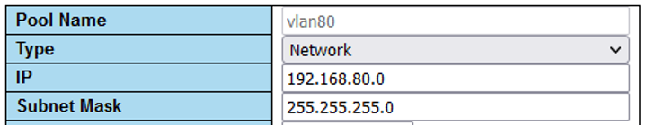
DHCP setup
The RU M-plane requires to setup a DHCP server. Go to Configuration -> DHCP -> server -> pool and create a new DHCP server with the following settings:
PTP Setup
For the PTP setup, follow the Fibrolan PTP Boundary Clock Configuration guide and use the following settings:
Device Type “Ord-Bound”
Profile “G8275.1”
Clock domain 24
VLAN 80
Also make sure you enable the used ports (4,15,16,17 in our case).
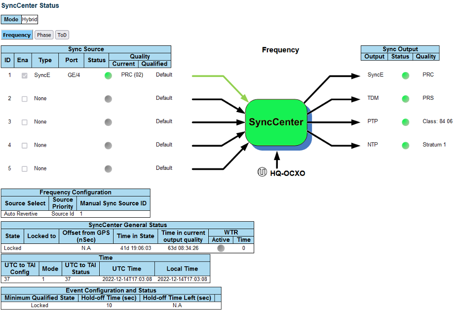
Hybrid mode is recommended for the sync mode.
If everything is configured correctly, the SyncCenter shows green.
Chapter 2.3 PTP Setup
These commands assume that PTP4L runs on the ens6f0 NIC interface and uses the CPU core 20.
Core clash can cause problems, so if a different core is to be used, it must not be used by L1 or L2+.
Verify Inbound PTP Packets
Typically, you see packets with ethertype 0x88f7 on the selected interface.
            $ sudo tcpdump -i ens6f0 -c 5 | grep ethertype
tcpdump: verbose output suppressed, use -v or -vv for full protocol decode
listening on ens6f1, link-type EN10MB (Ethernet), capture size 262144 bytes
13:27:41.291503 48:b0:2d:63:83:ac (oui Unknown) > 01:1b:19:00:00:00 (oui Unknown), ethertype Unknown (0x88f7), length 60:
13:27:41.291503 48:b0:2d:63:83:ac (oui Unknown) > 01:1b:19:00:00:00 (oui Unknown), ethertype Unknown (0x88f7), length 60:
13:27:41.296727 c4:5a:b1:14:1a:c6 (oui Unknown) > 01:1b:19:00:00:00 (oui Unknown), ethertype Unknown (0x88f7), length 78:
13:27:41.296784 c4:5a:b1:14:1a:c6 (oui Unknown) > 01:1b:19:00:00:00 (oui Unknown), ethertype Unknown (0x88f7), length 60:
13:27:41.306316 08:c0:eb:71:e7:d5 (oui Unknown) > 01:1b:19:00:00:00 (oui Unknown), ethertype Unknown (0x88f7), length 58:
Create ptp4l configuration file
Paste these commands into the shell to create the three configuration files.
            cat <<EOF | sudo tee /etc/ptp.conf
[global]
priority1 128
priority2 128
domainNumber 24
tx_timestamp_timeout 30
dscp_event 46
dscp_general 46
logging_level 6
verbose 1
use_syslog 0
logMinDelayReqInterval 1
[ens6f0]
logAnnounceInterval -3
announceReceiptTimeout 3
logSyncInterval -4
logMinDelayReqInterval -4
delay_mechanism E2E
network_transport L2
EOF

cat <<EOF | sudo tee /lib/systemd/system/ptp4l.service
[Unit]
Description=Precision Time Protocol (PTP) service
Documentation=man:ptp4l

[Service]
Restart=always
RestartSec=5s
Type=simple
ExecStart=/usr/bin/taskset -c 20 /usr/sbin/ptp4l -f /etc/ptp.conf

[Install]
WantedBy=multi-user.target
EOF
Create phc2sys Configuration File
            # If more than one instance is already running, kill the existing
# PHC2SYS sessions.

# Command used can be found in /lib/systemd/system/phc2sys.service
# Update the ExecStart line to the following, assuming ens6f0 interface is used.
$ sudo nano /lib/systemd/system/phc2sys.service

[Unit]
Description=Synchronize system clock or PTP hardware clock (PHC)
Documentation=man:phc2sys
After=ntpdate.service
Requires=ptp4l.service
After=ptp4l.service

[Service]
Restart=always
RestartSec=5s
Type=simple
ExecStart=/usr/sbin/phc2sys -a -r -n 24 -R 256 -u 256

[Install]
WantedBy=multi-user.target

#Note: If there is more than one ptp4l service running on the server the port must be explicitly specified, e.g:
ExecStart=/bin/sh -c "/usr/sbin/phc2sys -s /dev/ptp$(ethtool -T ens6f0 | grep PTP | awk '{print $4}')-c CLOCK_REALTIME -n 24 -O 0 -R 256 -u 256"
Enable and Start phc2sys and ptp4l
After changing those configuration files they need to be reloaded, enabled, and restarted. These services can be restarted if they don’t sync.
            $ sudo systemctl daemon-reload
$ sudo systemctl enable ptp4l.service
$ sudo systemctl enable phc2sys.service

$ sudo systemctl restart phc2sys.service ptp4l.service

# check that the service is active and has low rms value (<30):
~$ systemctl status ptp4l.service phc2sys.service
● ptp4l.service - Precision Time Protocol (PTP) service
     Loaded: loaded (/lib/systemd/system/ptp4l.service; enabled; vendor preset: enabled)
     Active: active (running) since Tue 2023-05-09 13:21:12 UTC; 14s ago
       Docs: man:ptp4l
   Main PID: 6962 (ptp4l)
      Tasks: 1 (limit: 94588)
     Memory: 544.0K
     CGroup: /system.slice/ptp4l.service
             └─6962 /usr/sbin/ptp4l -f /etc/ptp.conf

May 09 13:21:17 aerial-rf-gb-gnb taskset[6962]: ptp4l[15552.609]: rms   15 max   32 freq   -639 +/-  25 delay   211 +/-   1
May 09 13:21:18 aerial-rf-gb-gnb taskset[6962]: ptp4l[15553.609]: rms   21 max   29 freq   -583 +/-  12 delay   210 +/-   1
May 09 13:21:19 aerial-rf-gb-gnb taskset[6962]: ptp4l[15554.609]: rms   11 max   21 freq   -576 +/-   8 delay   211 +/-   1
May 09 13:21:20 aerial-rf-gb-gnb taskset[6962]: ptp4l[15555.609]: rms    6 max   13 freq   -579 +/-   8 delay   211 +/-   1
May 09 13:21:21 aerial-rf-gb-gnb taskset[6962]: ptp4l[15556.609]: rms    4 max    7 freq   -578 +/-   6 delay   212 +/-   0
May 09 13:21:22 aerial-rf-gb-gnb taskset[6962]: ptp4l[15557.609]: rms    5 max   11 freq   -589 +/-   6 delay   213 +/-   1
May 09 13:21:23 aerial-rf-gb-gnb taskset[6962]: ptp4l[15558.609]: rms    6 max   12 freq   -593 +/-   8 delay   210 +/-   1
May 09 13:21:24 aerial-rf-gb-gnb taskset[6962]: ptp4l[15559.609]: rms    3 max    7 freq   -587 +/-   5 delay   211 +/-   1
May 09 13:21:25 aerial-rf-gb-gnb taskset[6962]: ptp4l[15560.609]: rms    5 max   12 freq   -582 +/-   7 delay   212 +/-   1
May 09 13:21:26 aerial-rf-gb-gnb taskset[6962]: ptp4l[15561.609]: rms    4 max    7 freq   -587 +/-   7 delay   213 +/-   1

● phc2sys.service - Synchronize system clock or PTP hardware clock (PHC)
     Loaded: loaded (/lib/systemd/system/phc2sys.service; enabled; vendor preset: enabled)
     Active: active (running) since Tue 2023-05-09 13:21:12 UTC; 14s ago
       Docs: man:phc2sys
   Main PID: 6963 (phc2sys)
      Tasks: 1 (limit: 94588)
     Memory: 572.0K
     CGroup: /system.slice/phc2sys.service
             └─6963 /usr/sbin/phc2sys -a -r -n 24 -R 256 -u 256

May 09 13:21:17 aerial-rf-gb-gnb phc2sys[6963]: [15553.320] CLOCK_REALTIME rms   42 max   79 freq  +8240 +/- 368 delay  1762 +/-  16
May 09 13:21:18 aerial-rf-gb-gnb phc2sys[6963]: [15554.336] CLOCK_REALTIME rms   35 max   64 freq  +8091 +/- 303 delay  1754 +/-  13
May 09 13:21:19 aerial-rf-gb-gnb phc2sys[6963]: [15555.352] CLOCK_REALTIME rms   27 max   52 freq  +8218 +/- 224 delay  1752 +/-  13
May 09 13:21:20 aerial-rf-gb-gnb phc2sys[6963]: [15556.368] CLOCK_REALTIME rms   21 max   49 freq  +8153 +/- 152 delay  1758 +/-  16
May 09 13:21:21 aerial-rf-gb-gnb phc2sys[6963]: [15557.384] CLOCK_REALTIME rms   17 max   39 freq  +8149 +/- 125 delay  1761 +/-  16
May 09 13:21:22 aerial-rf-gb-gnb phc2sys[6963]: [15558.400] CLOCK_REALTIME rms   14 max   33 freq  +8185 +/- 101 delay  1750 +/-  14
May 09 13:21:23 aerial-rf-gb-gnb phc2sys[6963]: [15559.416] CLOCK_REALTIME rms   12 max   32 freq  +8138 +/-  63 delay  1752 +/-  13
May 09 13:21:24 aerial-rf-gb-gnb phc2sys[6963]: [15560.431] CLOCK_REALTIME rms   11 max   43 freq  +8171 +/-  54 delay  1756 +/-  15
May 09 13:21:25 aerial-rf-gb-gnb phc2sys[6963]: [15561.447] CLOCK_REALTIME rms   10 max   32 freq  +8163 +/-  38 delay  1762 +/-  16
May 09 13:21:26 aerial-rf-gb-gnb phc2sys[6963]: [15562.463] CLOCK_REALTIME rms    9 max   23 freq  +8162 +/-  17 delay  1761 +/-  16
Disable NTP
Enter these commands to turn off NTP:
            $ sudo timedatectl set-ntp false
$ timedatectl
Local time: Thu 2022-02-03 22:30:58 UTC
           Universal time: Thu 2022-02-03 22:30:58 UTC
                 RTC time: Thu 2022-02-03 22:30:58
                Time zone: Etc/UTC (UTC, +0000)
System clock synchronized: no
              NTP service: inactive
          RTC in local TZ: no
Verfiy System Clock Synchronization
Make NTP inactive and sychronise the system clock:
            $ timedatectl
Local time: Thu 2022-02-03 22:30:58 UTC
           Universal time: Thu 2022-02-03 22:30:58 UTC
                 RTC time: Thu 2022-02-03 22:30:58
                Time zone: Etc/UTC (UTC, +0000)
System clock synchronized: yes
              NTP service: inactive
          RTC in local TZ: no
Chapter 2.4 Setup the Foxconn ORU
There is also a Tutorial video for setting up the Foxconn ORU.
Foxconn RPQN-7801E |
Connections and Settings |
|---|---|
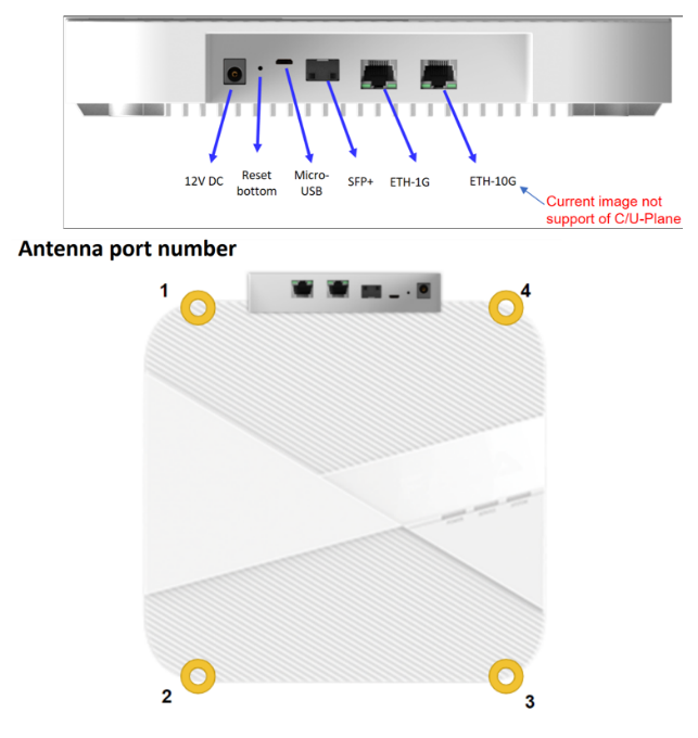
|
Connections:
GrandMaster settings (Qulsar):
/home/root/sdcard/RRHconfig_xran.xml:
|
Configure VLAN and IP Address on the gNB Server
Add these instructions to the server startup script ‘/etc/rc.local’ so they are automatically run on reboot.
Configure this on the fronthaul port.
You must use IP addresses that do not match those in the example below:
            sudo ip link add link ens6f0 name ens6f0.2 type vlan id 2
sudo ip addr add 169.254.1.103/24 dev ens6f0.2
sudo ip link set up ens6f0.2
O-RU M-Plane Setup
Add the following to the bottom of /etc/profile and comment out the line with
set_qse.sh if it exists.
Set the interface initially to eth0 for firmware version 1, and to qse-eth after
upgrading to firmware version ≥ 2.
            interface=eth0
vlanid=2
ipLastOctet=20

ip link add link ${interface} name ${interface}.$vlanid type vlan id $vlanid
ip addr flush dev ${interface}
ip addr add 169.254.0.0/24 dev ${interface}
ip addr add 169.254.1.${ipLastOctet}/24 dev ${interface}.$vlanid
ip link set up ${interface}.$vlanid
Reboot the O-RU using the command ./reboot.sh and check the network configuration:
            # ip r
169.254.1.0/24 dev eth0.2 src 169.254.1.20
Update O-RU Configuration
Update configurations in /home/root/sdcard/RRHconfig_xran.xml.
            root@arria10:~/test# grep -v '<!-' ../sdcard/RRHconfig_xran.xml
RRH_DST_MAC_ADDR = 08:c0:eb:71:e7:d4 # To match fronthaul interface of DU
RRH_SRC_MAC_ADDR = 6C:AD:AD:00:04:6C # To match qse-eth of RU
RRH_EN_EAXC_ID = 0
RRH_EAXC_ID_TYPE1 = 0x0, 0x1, 0x2, 0x3
RRH_EAXC_ID_TYPE3 = 0x8, 0x9, 0xA, 0xB
RRH_EN_SPC = 1
RRH_RRH_LTE_OR_NR = 1
RRH_TRX_EN_BIT_MASK = 0x0f
RRH_RF_EN_BIT_MASK = 0x0f
RRH_CMPR_HDR_PRESENT = 0
RRH_CMPR_TYPE = 1, 1
RRH_CMPR_BIT_LENGTH = 9, 9
RRH_UL_INIT_SYM_ID = 0
RRH_TX_TRUNC_BITS = 4
RRH_RX_TRUNC_BITS = 4
RRH_MAX_PRB = 273
RRH_C_PLANE_VLAN_TAG = 0x0002 #To match vlan id set in cuphycontroller yaml file
RRH_U_PLANE_VLAN_TAG = 0x0002 #To match vlan id set in cuphycontroller yaml file
RRH_SLOT_TICKS_IN_SEC = 2000
RRH_SLOT_PERIOD_IN_SAMPLE = 61440
RRH_LO_FREQUENCY_KHZ = 3750000, 0
RRH_TX_POWER = 24, 24
RRH_TX_ATTENUATION = 12.0, 12.0, 12.0, 12.0
RRH_RX_ATTENUATION = 0.0, 0.0, 0.0, 0.0
RRH_BB_GENERAL_CTRL = 0x0, 0x0, 0x0, 0x0
RRH_RF_GENERAL_CTRL = 0x3, 0x1, 0x0, 0x0
RRH_PTPV2_GRAND_MASTER_MODE = 3
RRH_PTPV2_JITTER_LEVEL = 0
RRH_PTPV2_VLAN_ID = 0
RRH_PTPV2_IP_MODE = 4
RRH_PTPV2_GRAND_MASTER_IP = 192.167.27.150
RRH_PTPV2_SUB_DOMAIN_NUM = 24
RRH_PTPV2_ACCEPTED_CLOCK_CLASS = 135
RRH_TRACE_PERIOD = 10
Reboot O-RU
            cd /home/root/test/

./reboot
Run the following to enable the config
            cd /home/root/test/

./init_rrh_config_enable_cuplane
At this point the console becomes unresponsive and fills with prints related to PTP, AFE initialization, and packet counters.
This section can be skipped if you want to use the steps in Chapter 4.
In the latest version of SDKM the user can choose to install directly on the target machine or from a remote machine. SDKM uses ssh to connect to the server where it installs the gNB.
The installation guide for cuBB is located in the NVIDIA Developer Zone - Aerial SDK.
Steps to install ARC using SDK Manager can be found at https://docs.nvidia.com/sdk-manager/install-with-sdkm-aerial/index.html
You can download the installer at https://developer.download.nvidia.com/sdkmanager/redirects/sdkmanager-deb.html
You must have Aerial SDK Early Access and ARC developer program approvals. Reach out to arc@nvidia.com for ARC developer program membership.
Prerequisites for Installing gNB with SDK Manager
Use the Aerial Installation Guide for the following steps:
Configure BIOS Settings
Install Ubuntu 22.04 Server
Install the Low-Latency Kernel
Configure Linux Kernel Command-line
Post-Installation Steps
Configure OAI L2.
IP addresses of the CN and the gNB must be configured using one of the following:
the gnb_cn5g_network_config.ini file and gnb_apply_network_config.sh script
the ARC installation guide steps to do it manually
Build the OAI L2+ image.
Follow the steps in the ARC Installation Guide.
Start the Aerial container.
See the ARC Installation Guide for recommended Docker run parameters. SDKmanager will start the Aerial container.
Start the OAI L2+ container.
See the ARC Installation Guide for recommended Docker run parameters.
Build the Aerial container.
Follow the instructions in the ARC Installation Guide.
This section is required only if you skipped the steps in Chapter 3.
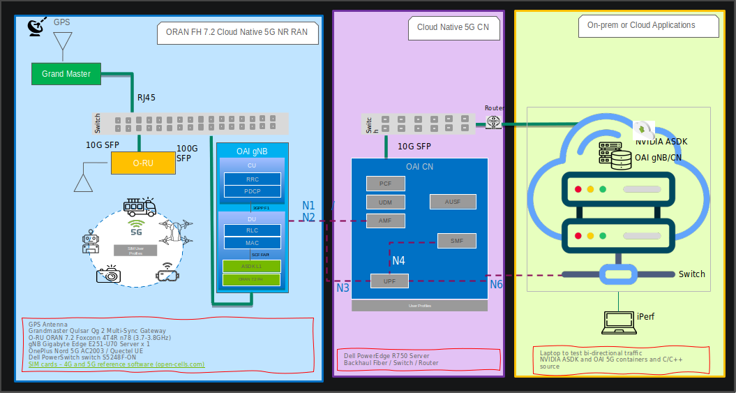
This section describes how to setup the Aerial private 5G network which consists of:
Aerial SDK L1
Remaining components of OAI gNB
OAI Core Network
User Equipment (UE)
Edge Server Applications (for example, iPerf)
Refer to the ARC Software Release Manifest at the beginning of the Installation Guide for current software versions supported by this ARC release.
Setup Aerial SDK L1
In the installation guide for the cuBB version specified in the ARC Software Release Manifest, find the Aerial SDK L1. Then, follow the instructions in the Installing ARC using SDK Manager section.
You can also refer to the following tutorial videos for installation steps:
Running the cuBB Docker Container
            export GPU_FLAG="--gpus all"
export cuBB_SDK=/opt/nvidia/cuBB
#Name of your docker container
export AERIAL_CUBB_CONTAINER=cuBB_$USER
#Docker image downloaded from NGC
export AERIAL_CUBB_IMAGE=nvcr.io/ea-aerial-sdk/aerial:23-2-cubb

sudo docker run --detach --privileged \
   -it $GPU_FLAG --name $AERIAL_CUBB_CONTAINER \
   --hostname c_aerial_$USER \
   --add-host c_aerial_$USER:127.0.0.1 \
   --network host \
   --shm-size=4096m \
   -e cuBB_SDK=$cuBB_SDK \
   -w $cuBB_SDK \
   -v $(echo ~):$(echo ~) \
   -v /dev/hugepages:/dev/hugepages \
   -v /usr/src:/usr/src \
   -v /lib/modules:/lib/modules \
   -v ~/share:/opt/cuBB/share \
   --userns=host \
   --ipc=host \
   -v /var/log/aerial:/var/log/aerial \
   $AERIAL_CUBB_IMAGE

docker exec -it $AERIAL_CUBB_CONTAINER bash
For installation instructions, see the Aerial cuBB Installation Guide, in the link above.
Since the cuBB 22.2.2 release, the test vectors are not included in the SDK. You need to generate the TV files before running cuPHY examples or cuBB end-to-end tests.
Using Aerial Python mcore Module
There is no Matlab license required to generate TV files using the Aerial Python mcore module. The cuBB Container already has aerial_mcore installed. To generate the TV files, run the following commands inside the Aerial container:
The TV generation can take a few hours on the devkit with the current isocpus parameter setting in the kernel command line. Make sure that the host has sufficient space to contain 111GB of TV files.
            cd ${cuBB_SDK}/5GModel/aerial_mcore/examples
source ../scripts/setup.sh
export REGRESSION_MODE=1
time python3 ./example_5GModel_regression.py allChannels
echo $?
ls -alF GPU_test_input/
du -h GPU_test_input/
Example output is shown below. The “real” time takes less than one hour on a 24 cores x86 host. The “echo $?” shows the exit code of the process, which should be 0. A non-zero exit code indicates a failure.
            Channel  Compliance_Test  Error   Test_Vector  Error  Performance_Test   Fail
------------------------------------------------------------------------------
SSB           37            0         42          0           0            0
PDCCH         71            0         80          0           0            0
PDSCH        274            0        286          0           0            0
CSIRS         86            0         87          0           0            0
DLMIX          0            0        1049          0           0            0
PRACH         60            0         60          0          48            0
PUCCH        469            0        469          0          96            0
PUSCH        388            0        398          0          41            0
SRS          125            0        125          0           0            0
ULMIX          0            0        576          0           0            0
BFW           58            0         58          0           0            0
------------------------------------------------------------------------------
Total       1568            0       3230          0         185            0

Total time for runRegression is 2147 seconds
Parallel pool using the 'local' profile is shutting down.

real    36m51.931s
user    585m1.704s
sys     10m28.322s
To Generate the launch pattern for each test case using cubb_scripts:
            cd $cuBB_SDK
cd cubb_scripts
python3 auto_lp.py -i ../5GModel/aerial_mcore/examples/GPU_test_input -t launch_pattern_nrSim.yaml
Then copy the launch pattern and TV files to testVectors repo.
            cd $cuBB_SDK
cp ./5GModel/aerial_mcore/examples/GPU_test_input/TVnr_* ./testVectors/.
cp ./5GModel/aerial_mcore/examples/GPU_test_input/launch_pattern* ./testVectors/multi-cell/.
Using Matlab
To generate TV files using Matlab, run the following command in Matlab:
cd('nr_matlab'); startup; [nTC, errCnt] = runRegression({'TestVector'}, {'allChannels'}, 'compact', [0, 1] );
All the cuPHY TVs are generated and stored under nr_matlab/GPU_test_input.
Generate the launch pattern for each test case using cubb_scripts:
            cd $cuBB_SDK
cd cubb_scripts
python3 auto_lp.py -i ../5GModel/nr_matlab/GPU_test_input -t launch_pattern_nrSim.yaml
Copy the launch pattern and TV files to testVectors repo.
            cd $cuBB_SDK
cp ./5GModel/nr_matlab/GPU_test_input/TVnr_* ./testVectors/.
cp ./5GModel/nr_matlab/GPU_test_input/launch_pattern* ./testVectors/multi-cell/.
Setup OAI gNB
Clone the gNB Source Code
Clone the OpenAirInterface5G repository. Access to the private branch is required. For access contact NVIDIA.
            git clone --branch OAI_Aerial_v2.0 https://gitlab.eurecom.fr/rssilva/openairinterface5g.git ~/openairinterface5g

cd openairinterface5g
gNB Configuration File
Update the configuration of OAI L2. The configuration is located here ~/openairinterface5g/targets/PROJECTS/GENERIC-NR-5GC/CONF/vnf.sa.band78.fr1.273PRB.Aerial.conf
NVIDIA tested configuration files are available NGC https://registry.ngc.nvidia.com/orgs/ea-aerial-sdk/teams/aerial/resources/arc-full-stack
When building a Docker image the files are copied from the filesystem into the image. Changes in the configuration after you build the image must also be done inside the container.
Build gNB Docker Image
            export OAI_GNB_IMAGE=i_oai_aerial:latest
docker build --tag $OAI_GNB_IMAGE . -f docker/Dockerfile.aerial.ubuntu20
Setup OAI CN5G
Do the iptables setup, below, after every a system reboot. Or make this permanent in your Ubuntu system configuration.
            On CN5G server, configure it to allow the traffic coming in by
adding this rule to iptables:

# On CN5G, upon startup:

sudo sysctl net.ipv4.conf.all.forwarding=1
sudo iptables -P FORWARD ACCEPT
Install the core network by following these steps.
To run the correct configuration for Aerial Research Cloud replace section 2.2 and 2.3 OAI CN5G configuration files with the following:
             # Get openairinterface5g source code
 git clone --branch OAI_Aerial_v2.0 https://gitlab.eurecom.fr/rssilva/openairinterface5g.git ~/openairinterface5g
 cd ~/openairinterface5g
 cp -rT ~/openairinterface5g/doc/tutorial_resources/oai-cn5g ~/oai-cn5g

docker pull mysql:8.0
docker pull oaisoftwarealliance/oai-amf:develop
docker pull oaisoftwarealliance/oai-nrf:develop
docker pull oaisoftwarealliance/oai-smf:develop
docker pull oaisoftwarealliance/oai-udr:develop
docker pull oaisoftwarealliance/oai-udm:develop
docker pull oaisoftwarealliance/oai-ausf:develop
docker pull oaisoftwarealliance/oai-spgwu-tiny:develop
docker pull oaisoftwarealliance/trf-gen-cn5g:jammy
docker build --target ims --tag asterisk-ims:develop --file ~/oai-cn5g/Dockerfile .
The user configurable configuration files are:
~/oai-cn5g/database/oai_db.sql
Configuring OAI gNB and CN5G
For the purpose of understanding which address is what in the example configuration setting and commands below, we will assume the gNB and CN5G servers have these interface names and IP addresses.
CN5G Server
            eno1: 10.31.66.x            = SSH management port for terminal
eno2: 169.254.200.6         = BH connection on SFP switch for gNB-CN5G traffic
gNB Server
            eno1:     10.31.66.x        = SSH management port for terminal
ens6f0:   b8:ce:f6:4e:75:40 = FH MAC address
ens6f0.2: 169.254.1.105     = FH IP address
ens6f1:   169.254.200.5     = BH connection SFP switch for gNB-CN5G traffic
gNB to set static route
On the gNB server, add this static route for a path to the CN5G server. Apply this route after each server power-on.
            Syntax:
sudo ip route add 192.168.70.128/26 via <CN5G IP> dev <gNB interface for CN5G>

Example:
sudo ip route add 192.168.70.128/26 via 169.254.200.6 dev ens6f1
gNB to set the CN5G server to uses for AMF
Edit gNB configuration file: targets/PROJECTS/GENERIC-NR-5GC/CONF/vnf.sa.band78.fr1.273PRB.Aerial.conf
Below is an example with lab-specific network parameters. Your IP address and interface names may differ.
            GNB_INTERFACE_NAME_FOR_NG_AMF = "ens6f1";       # gNB side interface name of the SFP port toward CN (was eno1)
GNB_IPV4_ADDRESS_FOR_NG_AMF = "169.254.200.5";  # gNB side IP address of interface above (was 172.21.16.130)
GNB_INTERFACE_NAME_FOR_NGU = "ens6f1";          # gNB side interface name of the SFP port toward CN (was eno1)
GNB_IPV4_ADDRESS_FOR_NGU = "169.254.200.5";     # Same IP as GNB_IPV4_ADDRESS_FOR_NG_AMF above (was 172.21.16.130)
Running CN5G
To start CN5G
docker-compose up -d
To Stop CN5G
docker-compose down
To monitor CN5G logs while running
docker logs oai-amf -f
To capture PCAPs
            docker exec -it oai-amf /bin/bash
apt update && apt install tcpdump -y
tcpdump -i any -w /tmp/amf.pcap
Then copy the pcap out from the container.
docker cp oai-amf:/tmp/amf.pcap .
Example Screenshot of Starting CN5G
            aerial@aerial-rf-r630:~/oai-cn5g$ docker compose up -d
[+] Building 0.0s (0/0)
[+] Running 11/11
✔ Network demo-oai-public-net  Created                                                                     0.1s
✔ Container oai-nrf            Started                                                                     0.7s
✔ Container mysql              Started                                                                     0.7s
✔ Container asterisk-ims       Started                                                                     0.7s
✔ Container oai-udr            Started                                                                     0.9s
✔ Container oai-udm            Started                                                                     1.2s
✔ Container oai-ausf           Started                                                                     1.5s
✔ Container oai-amf            Started                                                                     1.7s
✔ Container oai-smf            Started                                                                     2.0s
✔ Container oai-spgwu-tiny     Started                                                                     2.3s
✔ Container oai-ext-dn         Started                                                                     2.6s
            aerial@aerial-rf-r630:~/oai-cn5g$ docker ps
CONTAINER ID   IMAGE                                       COMMAND                  CREATED              STATUS                        PORTS                          NAMES
d5af4f51c393   oaisoftwarealliance/trf-gen-cn5g:latest     "/bin/bash -c ' ip r…"   About a minute ago   Up About a minute (healthy)                                  oai-ext-dn
a9b2d18c7f77   oaisoftwarealliance/oai-spgwu-tiny:v1.5.1   "python3 /openair-sp…"   About a minute ago   Up About a minute (healthy)   2152/udp, 8805/udp             oai-spgwu-tiny
b61c383f9e60   oaisoftwarealliance/oai-smf:v1.5.1          "python3 /openair-sm…"   About a minute ago   Up About a minute (healthy)   80/tcp, 8080/tcp, 8805/udp     oai-smf
3681b1048c53   oaisoftwarealliance/oai-amf:v1.5.1          "python3 /openair-am…"   About a minute ago   Up About a minute (healthy)   80/tcp, 9090/tcp, 38412/sctp   oai-amf
c602f7cb1c67   oaisoftwarealliance/oai-ausf:v1.5.1         "python3 /openair-au…"   About a minute ago   Up About a minute (healthy)   80/tcp                         oai-ausf
752acae83ac0   oaisoftwarealliance/oai-udm:v1.5.1          "python3 /openair-ud…"   About a minute ago   Up About a minute (healthy)   80/tcp                         oai-udm
4bf281d08229   oaisoftwarealliance/oai-udr:v1.5.1          "python3 /openair-ud…"   About a minute ago   Up About a minute (healthy)   80/tcp                         oai-udr
33aa959be775   mysql:8.0                                   "docker-entrypoint.s…"   About a minute ago   Up About a minute (healthy)   3306/tcp, 33060/tcp            mysql
5d22e4745d00   asterisk-ims:latest                         "asterisk -fp"           About a minute ago   Up About a minute (healthy)                                  asterisk-ims
1a93b3ffe305   oaisoftwarealliance/oai-nrf:v1.5.1          "python3 /openair-nr…"   About a minute ago   Up About a minute (healthy)   80/tcp, 9090/tcp               oai-nrf
Step 1: Add the SIM User Profile
Modify:
oai_db.sql (with plain text editor)
There are currently 3 UEs pre-configured here. To find them, search for: 001010000000001 and add or edit them as needed.
On gNB server, if you want to change the change the MCC and MNC in the gNB config file. ./targets/PROJECTS/GENERIC-NR-5GC/CONF/vnf.sa.band78.fr1.273PRB.Aerial.conf
Step 2: Setup the UE and SIM Card
For reference, use the following:
SIM cards – 4G and 5G reference software (open-cells.com)
Program SIM Card with Open Cells Project application “uicc-v2.6” https://open-cells.com/d5138782a8739209ec5760865b1e53b0/uicc-v2.6.tgz
Use the ADM code specific to the SIM card. If the wrong ADM is used 8 times, the SIM card is permanently locked.
            sudo ./program_uicc --adm 12345678 --imsi 001010000000001 --isdn 00000001 --acc 0001 --key fec86ba6eb707ed08905757b1bb44b8f --opc C42449363BBAD02B66D16BC975D77CC1 -spn "OpenAirInterface" --authenticate
Existing values in USIM
ICCID: 89860061100000000191
WARNING: iccid luhn encoding of last digit not done
USIM IMSI: 208920100001191
USIM MSISDN: 00000191
USIM Service Provider Name: OpenCells191
Setting new values
Reading UICC values after uploading new values
ICCID: 89860061100000000191
WARNING: iccid luhn encoding of last digit not done
USIM IMSI: 001010000000001
USIM MSISDN: 00000001
USIM Service Provider Name: OpenAirInterface
Succeeded to authentify with SQN: 64
set HSS SQN value as: 96
CUE Configuration Setup
Install the “Magic IPERF” application on the UE:
To test with CUE, a test SIM card with Milenage support is required. The following has to be provisioned on the SIM and it has to match the Core Network settings: mcc, mnc, IMSI, Ki, OPc
The APN on the CUE should be configured according to Core Network settings.
Start the DNS (Core network should assign mobile IP address and DNS. If DNS is not assigned, set DNS with other Android app).
Step 3. Running End-to-End OTA
This section describes how to run end-to-end traffic from UE to the edge core network.
UE can connect as close as 2-3 meters with a range of 10-15 meters. Connection distance outside of buildings is unverified.
Start CN5G Core Network
            sudo sysctl net.ipv4.conf.all.forwarding=1
sudo iptables -P FORWARD ACCEPT

cd ~/oai-cn5g
docker compose up -d
Start CN5G Edge Application
After the CN5G is started, use the oai-ext-dn container to run IPERF.
docker exec -it oai-ext-dn /bin/bash
Start NVIDIA Aerial cuBB on the gNB
            # Run on host: start a docker terminal
docker exec -it $AERIAL_CUBB_CONTAINER /bin/bash
Follow the Aerial documentation for building and running the cuphycontroller. The following instructions are for building and setting up the environment for running cuphycontroller. The following commands must be run from inside cuBB container.
            cd /opt/nvidia/cuBB
export cuBB_SDK=$(pwd)
mkdir build && cd build
cmake ..
time chrt -r 1 taskset -c 2-20 make -j
insModScript=${cuBB_SDK}/cuPHY-CP/external/gdrcopy/
cd $insModScript && make && ./insmod.sh && cd -
export LD_LIBRARY_PATH=$cuBB_SDK/gpu-dpdk/build/install/lib/x86_64-linux-gnu:$cuBB_SDK/build/cuPHY-CP/cuphydriver/src
export LD_LIBRARY_PATH=${LD_LIBRARY_PATH}:/opt/mellanox/gdrcopy/src
export LD_LIBRARY_PATH=${LD_LIBRARY_PATH}:/opt/mellanox/dpdk/lib/x86_64-linux-gnu:/opt/mellanox/doca/lib/x86_64-linux-gnu
echo $LD_LIBRARY_PATH | sed 's/:/\n/g' | sudo tee /etc/ld.so.conf.d/aerial-dpdk.conf
sudo ldconfig
export GDRCOPY_PATH_L=$cuBB_SDK/cuPHY-CP/external/gdrcopy/src

# Make sure MPS is running
export CUDA_DEVICE_MAX_CONNECTIONS=8
export CUDA_MPS_PIPE_DIRECTORY=/var
export CUDA_MPS_LOG_DIRECTORY=/var
# Stop existing MPS
sudo -E echo quit | sudo -E nvidia-cuda-mps-control
# Start MPS
sudo -E nvidia-cuda-mps-control -d
sudo -E echo start_server -uid 0 | sudo -E nvidia-cuda-mps-control
Configuration files for ARC can be found in NGC.
Aerial configuration files are located in /opt/nvidia/cuBB/cuPHY-CP/cuphycontroller/config.
Before running the cuphycontroller edit the configuration file (cuphycontroller_P5G_SCF_FXN.yaml) to point at the correct MAC address of the ORU and the correct PCIe address of FH interface of the gNB.
            sed -i "s/ nic:.*/ nic: 0000:b5:00.0/" ${cuBB_SDK}/cuPHY-CP/cuphycontroller/config/cuphycontroller_P5G_SCF_FXN.yaml
sed -i "s/ dst_mac_addr:.*/ dst_mac_addr: 6c:ad:ad:00:02:02/" ${cuBB_SDK}/cuPHY-CP/cuphycontroller/config/cuphycontroller_P5G_SCF_FXN.yaml
Start the cuphycontroller and wait fort L1 to start.
            # If you have an old phy.log you can remove or move it before starting. So you get the correct create/birth date.
rm -f /tmp/phy.log
# Start the cuphycontroller with the configuration from cuphycontroller_P5G_SCF_FXN.yaml
$cuBB_SDK/build/cuPHY-CP/cuphycontroller/examples/cuphycontroller_scf P5G_SCF_FXN

# Wait until you see a console log

====> PhyDriver initialized!

16:29:35.913840 C [NVIPC:DEBUG] ipc_debug_open: pcap enabled:
fapi_type=1 fapi_tb_loc=1

16:29:36.141657 C [NVIPC:SHM] shm_ipc_open: forward_enable=0
fw_max_msg_buf_count=0 fw_max_data_buf_count=0

16:29:36.153808 C [CTL.SCF] cuPHYController configured for 1 cells
16:29:36.153816 C [CTL.SCF]

====> cuPHYController initialized, L1 is ready!
Start OAI gNB L2 Stack on the gNB
Start up the OAI container and start the OAI nr-softmodem by entering the container to run the configuration file mounted from the host.
            export OAI_GNB_CONTAINER=c_oai_aerial_$USER
export OAI_GNB_IMAGE=i_oai_aerial:latest

docker run --detach --privileged --rm \
   --ipc host \
   --network host --shm-size=4096m -it \
   --cpuset-cpus=8-15 \
   --name $OAI_GNB_CONTAINER \
   -v /lib/modules:/lib/modules \
   -v /dev/hugepages:/dev/hugepages \
   -v /usr/src:/usr/src \
   -v ~/openairinterface5g:/opt/oai/ \
   -v ~/share:/opt/nvidia/cuBB/share \
   -v /var/log/aerial:/var/log/aerial \
   $OAI_GNB_IMAGE
            docker exec -it $OAI_GNB_CONTAINER bash

# cd to the openairinterface directory
source oaienv
cd cmake_targets/ran_build/build/
./nr-softmodem -O ../../../targets/PROJECTS/GENERIC-NR-5GC/CONF/vnf.sa.band78.fr1.273PRB.Aerial.conf --nfapi aerial --sa | ts | tee /var/log/aerial/oai.log
CUE Connecting to 5G Network
Take the CUE out of airplane mode to start the UE attaching to the network. Make sure that the CUE is in airplane mode before starting OAI L2 stack.
Observe 5G Connect Status
See Preamble log in cuphycontroller console output.
Check Core Network log or CUE log to see whether NAS authentication and PDU session succeed.
Running E2E IPERF Traffic
Start ping, iperf, or other network app tests after the PDU session connects successfully.
You can install and run the “Magic IPerf” Android application on the CUE for this purpose.
Ping Test
Ping the UE from the CN:
docker exec -it oai-ext-dn ping 12.1.1.2
Ping from the UE to the CN:
ping 192.168.70.135 -t -S 12.1.1.2
IPERF Downlink Test
UE Side:
iperf3 -s
CN5G Side:
docker exec -it oai-ext-dn iperf3 -u -i 60 -b 200m -p 5201 -t 60 -c 12.1.1.2
IPERF Uplink Test
UE Side:
iperf3 -s
CN5G Side:
docker exec -it oai-ext-dn iperf3 -u -i 60 -b 55m -p 5201 -R -t 60 -c 12.1.1.2
To stop the containers follow the following example:
            docker stop $OAI_GNB_CONTAINER
docker rm $OAI_GNB_CONTAINER
ARC is a P5G cellular network. Specific enterprise switching/routing/firewalls/policies might need integration support to enable access to World Wide Web.