System Setup and Installation#
System Configuration#
The following table outlines the details of the system that was used to run multi node training and inference workloads using a Linux KVM hypervisor.
Title |
Details |
|---|---|
Server Model |
Dell PowerEdge XE9680 |
CPU |
2x Intel® Xeon® Platinum 8648 |
System Memory |
2 TB, 32 x 64 GB DIMM |
GPU |
8 x HGX H200 |
NICs |
8 x NVIDIA Connect-X (CX7) |
Installing the Hypervisor#
This guide is based on Linux KVM hypervisors. Major enterprise distributions based on recent Linux kernels should have the necessary features to support your goals. Please consult your vendor documentation for a detailed installation process. A few items are important to be noted prior to the installation:
Boot drive selection: The hypervisor should be installed on a drive / controller that is not intended for use by guest VMs with GPUDirect Storage. Such drives / controllers cannot be shared between the hypervisor and guest VMs.
Network configuration: Network interfaces connected to PCI Express (PCIe) switches shouldn’t be used for the OS install and management. Use a LOM or a separate Ethernet NIC for this purpose and leave the other interfaces unconfigured.
Understanding System Topology#
To determine the NUMA and PCI Express topology of the server, use the lstopo -sv command (not installed by default in many distributions). On a system with switched PCI Express topology, peer-to-peer communication between devices is possible. This technology, called GPUDirect RDMA, allows a GPU to reach out to an NVMe disk or a NIC without the overhead of copying the data into the CPU memory space, thus saving significant computing time. Understanding and defining groups of PCI devices, usually one or two GPUs, one or more NIC(s), and sometimes an NVMe storage device, that share a common PCI Express switch is crucial for maintaining the underlying structure when virtual machines are created. In other words, PCI device hierarchy information is necessary to properly configure your virtual machines. It is strongly suggested to keep a copy of your topology file before continuing.
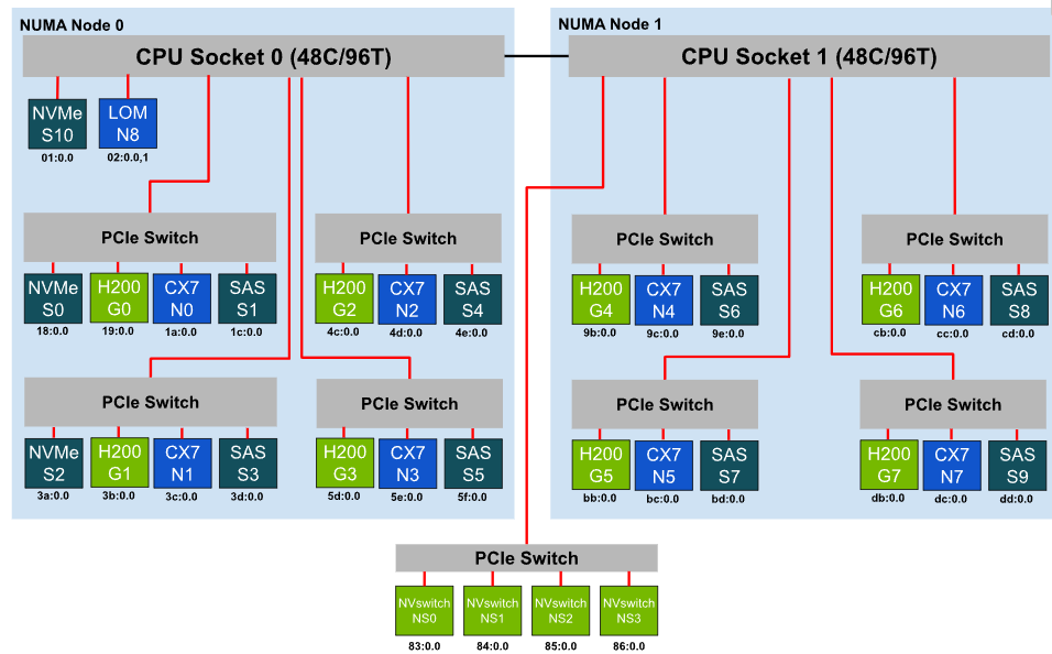
The following sections walk through an example topology from an NVIDIA H200 HGX 8-GPU platform. This server is equipped with dual processors (each with 48 cores / 96 threads), and eight NVIDIA ConnectX-7 Infiniband NICs.
Sample ‘lstopo’ output#
lstopo -sv output for the example H200 HGX 8-GPU platform:
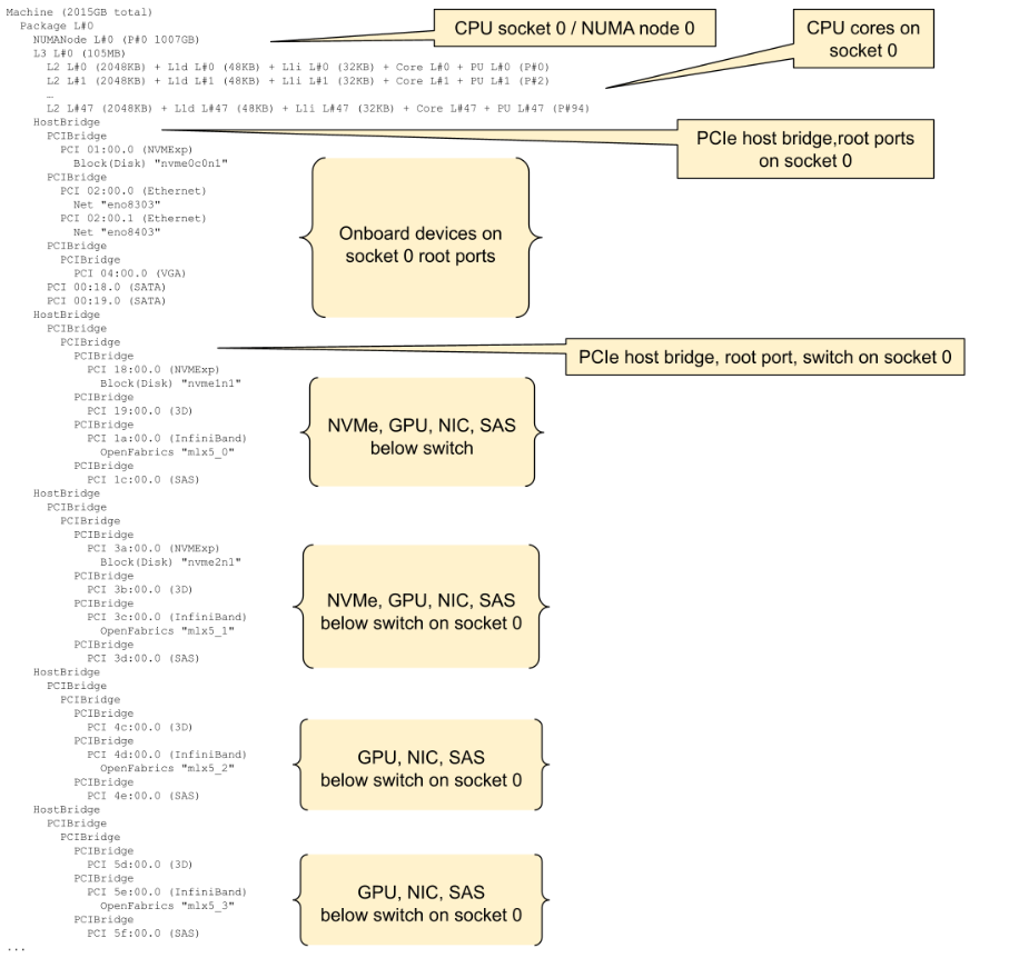
Sample lstopo -sv output (continues below)
Once you understand the PCI Express topology of the underlying host server, you can continue with the OS configuration to optimize the server for virtual applications. Make sure your virtualization stack is installed - the process of installing KVM, QEMU and its dependencies will vary between distributions, please consult with your vendor for the adequate procedure.
Additional System Setup Considerations#
PCIe Address Translation Services (ATS) must be enabled on the NIC and PCIe Access Control Services (ACS) must be configured on the PCIe switches and root ports to allow ATS in order to achieve maximum GPUDirect RDMA performance in a VM. Please refer to the Appendix for details on how to configure ATS and ACS.
Ensure that the ‘nvidia-peermem’ module is loaded in order to enable GPUDirect RDMA capabilities.
Disabling C-States may improve system stability
Reducing NUMA nodes per socket (NPS) and disabling simultaneous multithreading will simplify the PCIe device and core mappings, but may have a negative performance impact depending on your CPU model. Please consult with your vendor.
Do not install the NVIDIA driver on the bare metal host OS to prevent resource conflicts.
A cluster must be identically configured - hardware and firmware - in order to reliably be mass deployed using fixed hardware topology maps.
If your vendor offers a “latency-sensitive” performance mode in the system setup, enable it.
Optimal Device Selection#
When assigning GPUs, NICs, and Storage Controllers to VMs, these rules should be followed to maximize overall performance:
Select devices on the same CPU socket / NUMA node as the VM’s Virtual CPUs#
Bandwidth and latency between PCIe devices (GPUs, NICs, Storage Controllers) and system memory is optimal when accessing memory attached on the same CPU socket / NUMA node as the devices themselves. For example, for a half-sized VM on the HGX server there are two optimal configurations:
VM vCPUs pinned to CPU socket 0, VM system memory allocated from NUMA node 0, GPUs G0-G3, NICs N0-N3, Storage Controllers S0-S5, or
VM vCPUs pinned to CPU socket 1, VM system memory allocated from NUMA node 1, GPUs G4-G7, NICs N4-N7, Storage Controllers S6-S9.
If the VM’s resource requirements exceed the memory and device count available within a CPU socket / NUMA node, memory and devices on a different CPU socket may be used - but accessing this memory will come at some performance penalty, and PCIe peer-to-peer operation between devices on different CPU sockets won’t be possible.
Select NICs, Storage Controllers proximate to the GPU#
Proximity here refers specifically to the PCIe communication path length between the NICs or Storage Controllers and the GPU. GPUDirect RDMA or GPUDirect Storage rely on PCIe peer-to-peer transactions between the GPU and NICs or Storage Controllers. Best GPUDirect performance is obtained when GPUs and peer devices are below the same PCIe switch. Performance may degrade as the PCIe path length increases, traversing multiple PCIe switches or the PCIe root complex. GPUDirect will not operate when GPU and peer devices are on separate CPU sockets.
Device topology relationship (best to worst) |
Example device groupings (not exhaustive) |
|---|---|
GPU and peer device below the same PCIe switch |
GPU G0, NIC N0, Storage S0, S1 GPU G1, NIC N1, Storage S2, S3 GPU G2, NIC N2, Storage S4 GPU G3, NIC N3, Storage S5 GPU G4, NIC N4, Storage S6 GPU G5, NIC N5, Storage S7 GPU G6, NIC N6, Storage S8 GPU G7, NIC N7, Storage S9 |
GPU and peer device below a common PCIe switch |
(This configuration only occurs when PCIe switches are stacked. There is no such configuration in the H200 server example) |
GPU and peer device below a common PCIe root complex / NUMA node |
GPU G0, NIC N2, Storage S5 GPU G2, NIC N1, Storage S0 GPU G4, NIC N7, Storage S8 GPU G7, NIC N5, Storage S6 |
GPU and peer device on separate NUMA nodes |
GPU G1, NIC N4, Storage S8 GPU G5, NIC N2, Storage S3 |
GPU and peer device on separate CPU sockets |
(As above, because the H200 server example only has one NUMA node per CPU socket) |
Select GPUs connected via NVLink#
HGX platforms have all-to-all GPU NVLink connectivity so this is less of a factor.
Fractional or shared NVSwitch multi-tenant mode configurations with 2x VMs with 4 GPUs/NICs each or 4 x GPUs/NICs each should also follow the rules above to maximize overall performance. However, please note that shared, multi-VM passthrough deployments require partitioning the NVSwitch fabric. This scenario requires writing a custom client using the Fabric Manager SDK and the example libvirt XML for a multi-VM deployment is outside the scope of this whitepaper. Refer to Fabric Manager documentation for additional information.