Initial Cluster Setup
The deployment stage of a DGX SuperPOD consists of using BCM to provision and manage the Slurm cluster.
Configure the NFS server.
User home directories (home/) and shared data (cm_shared/) directories must be shared between head nodes (such as the DGX OS image) and must be stored on an NFS filesystem for HA availability. Because DGX SuperPOD does not mandate the nature of the NFS storage, the configuration is outside the scope of this document. This DGX SuperPOD deployment uses the NFS export path provided in the site survey /var/nfs/general. The following parameters are recommended for the NFS server export file /etc/exports.
/var/nfs/general *(rw,sync,no_root_squash,no_subtree_check)
Configure the DGX systems to PXE boot by default.
Using either KVM or a crash cart, connect to the DGX system, enter the BIOS menu, and configure Boot Option #1 to be [NETWORK].
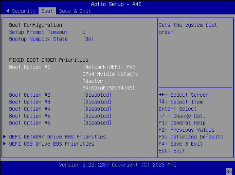
Ensure that other Boot Options are [Disabled] and go to the next screen.
Set Boot Option #1 and Boot Option #2 to use IPv4 for Storage 4-2 and Storage 5 2.
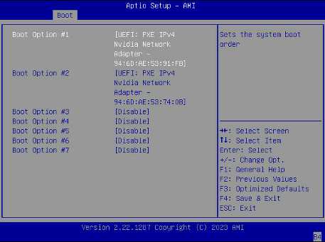
Ensure that other Boot Options are [Disabled].
Select Save & Exit.
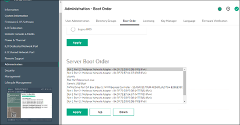
On the failover head node and the CPU nodes, ensure that Network boot is configured as the primary option. Ensure that the Mellanox ports connected on the network on the head and CPU nodes are set to Ethernet mode as well.
This is an example of a system that will boot from the network with Slot 1 Port 2 and Slot 2 Port 2.
Download the BCM installer ISO.
Burn the ISO to a DVD or to a bootable USB device.
It can also be mounted as virtual media and installed using the BMC. The specific mechanism for the latter will vary by vendor.
Ensure that the BIOS of the target head node is configured in UEFI mode and that its boot order is configured to boot the media containing the BCM installer image.
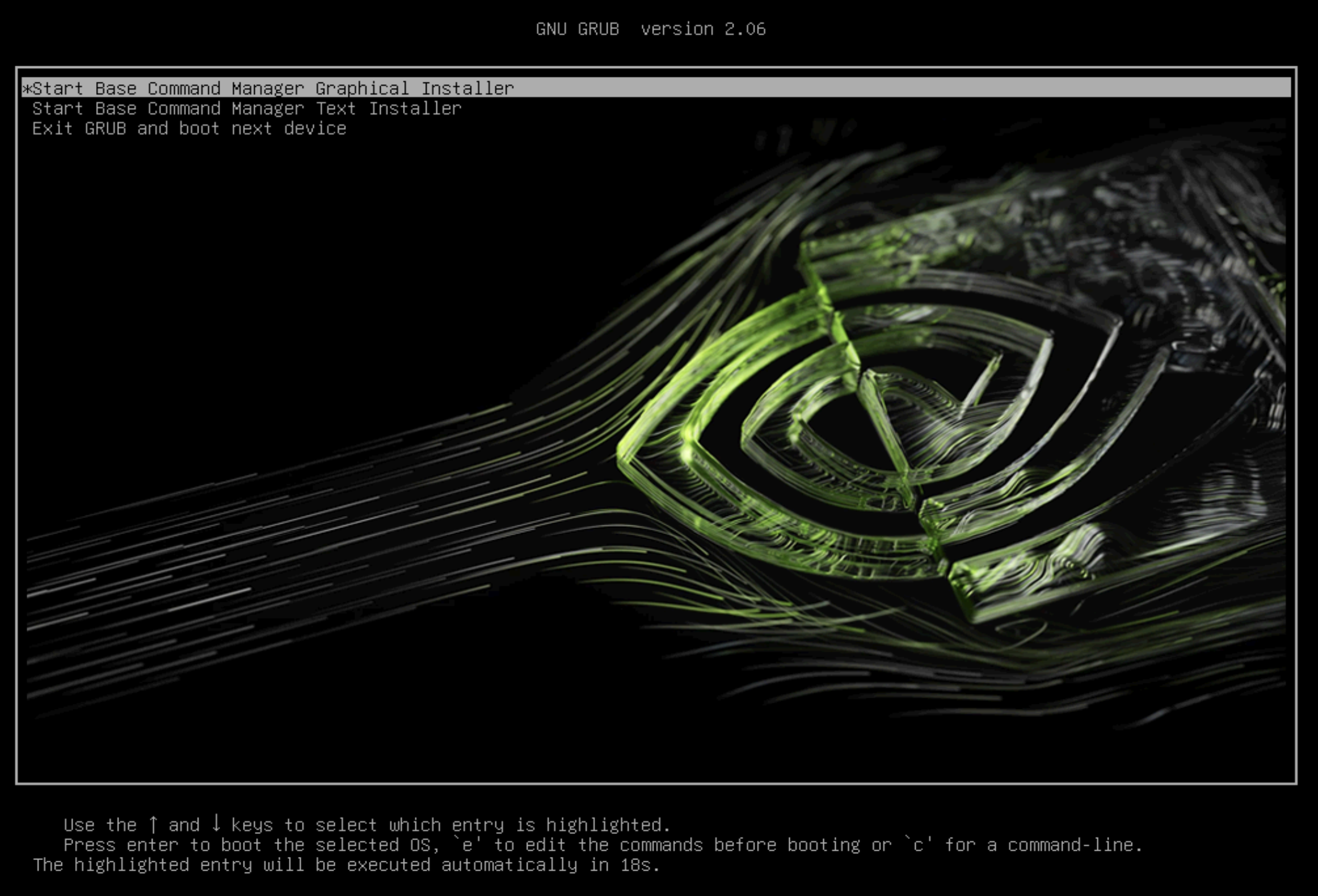
Boot the installation media.
At the grub menu, choose Start Base Command Manager Graphical Installer.
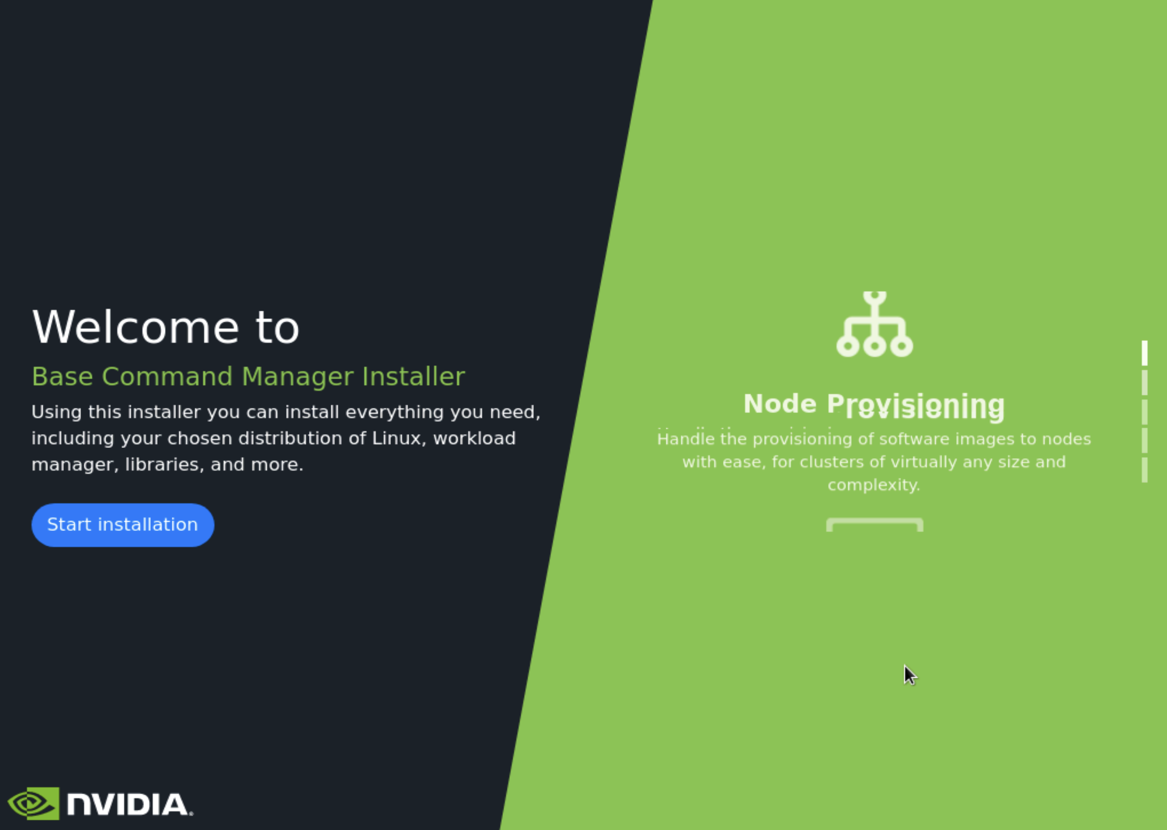
Select Start installation on the splash screen.
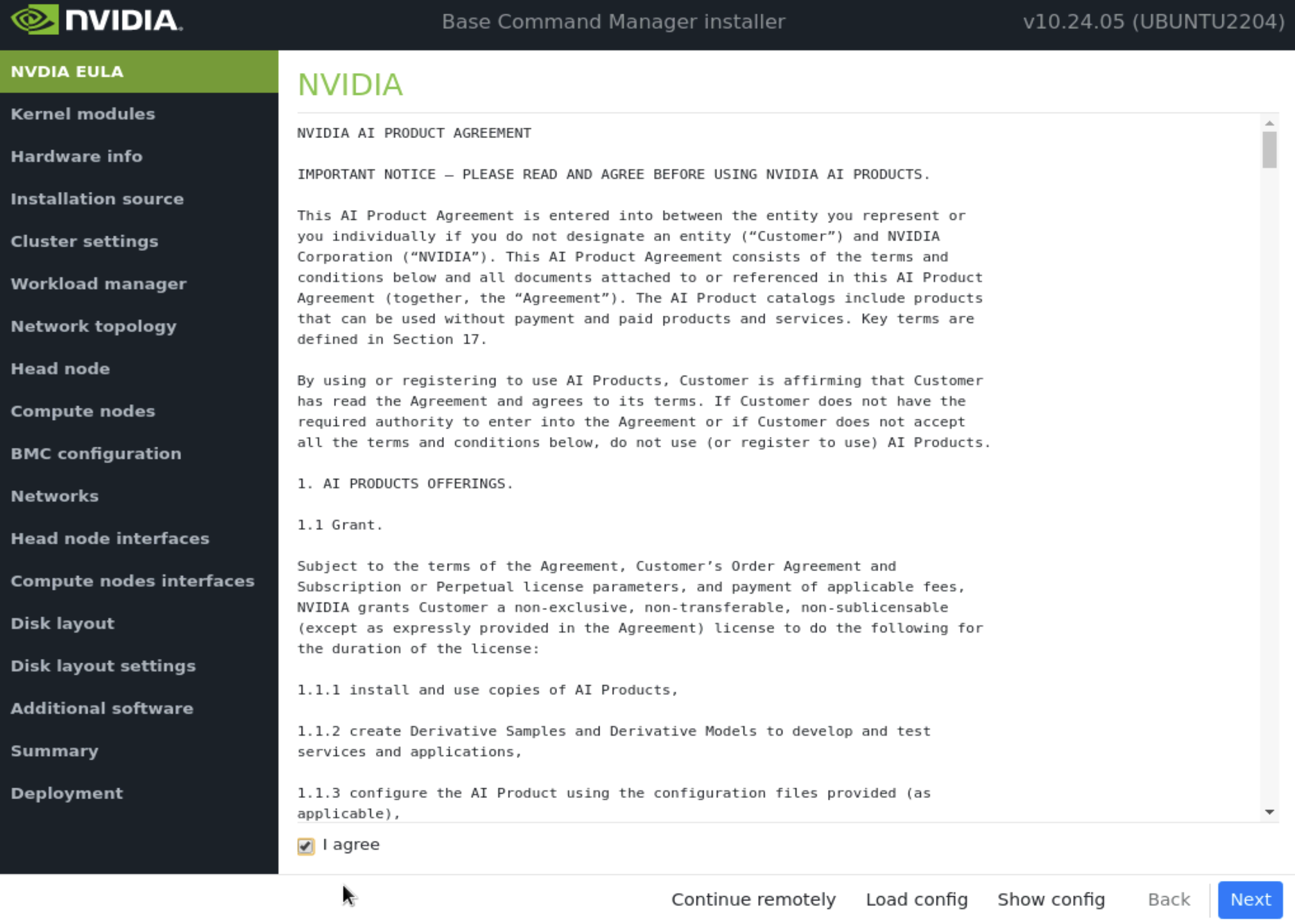
Accept the terms of the NVIDIA EULA by checking I agree and then select Next.
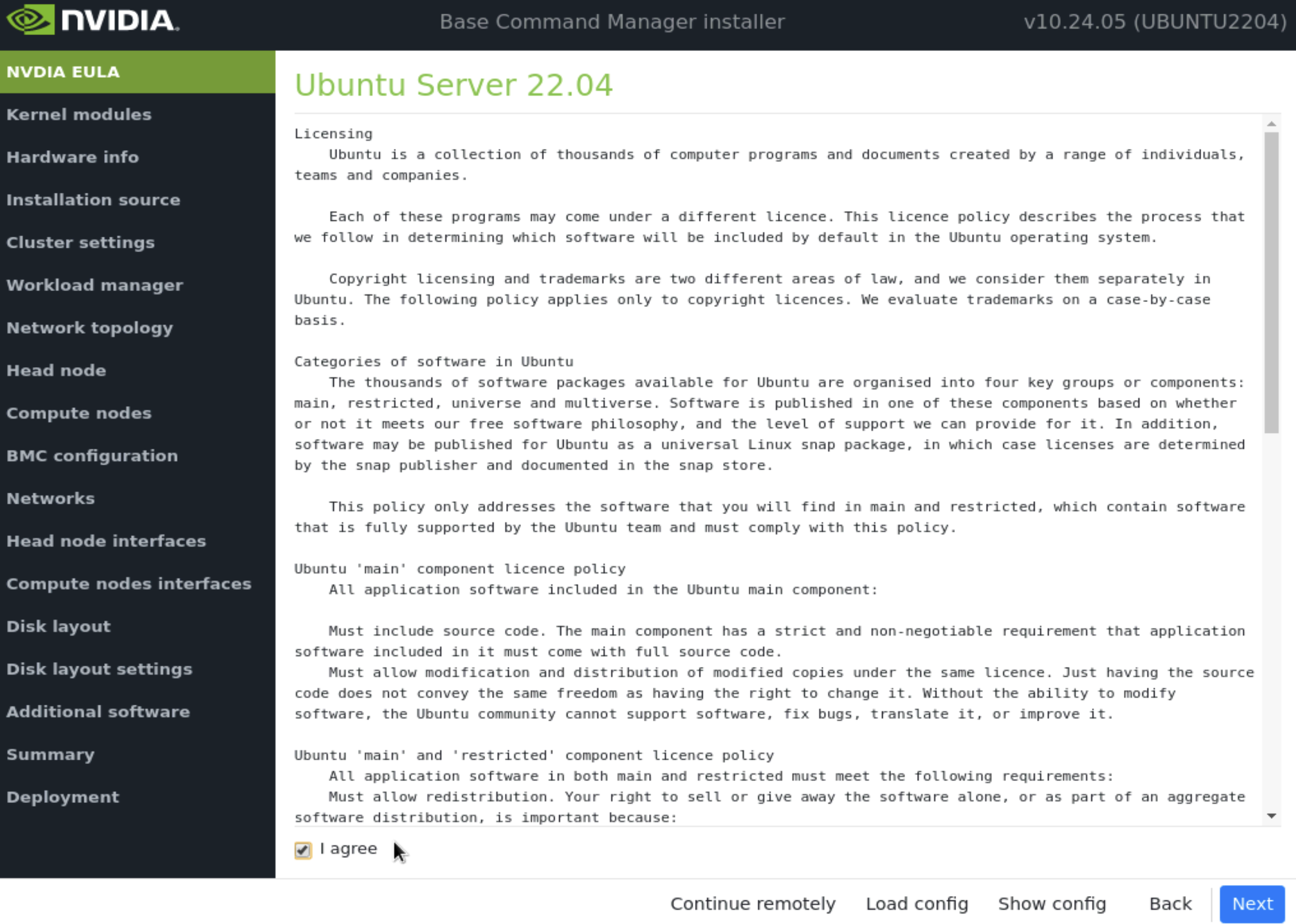
Accept the terms of the Ubuntu Server UELA by checking I agree and then select Next.
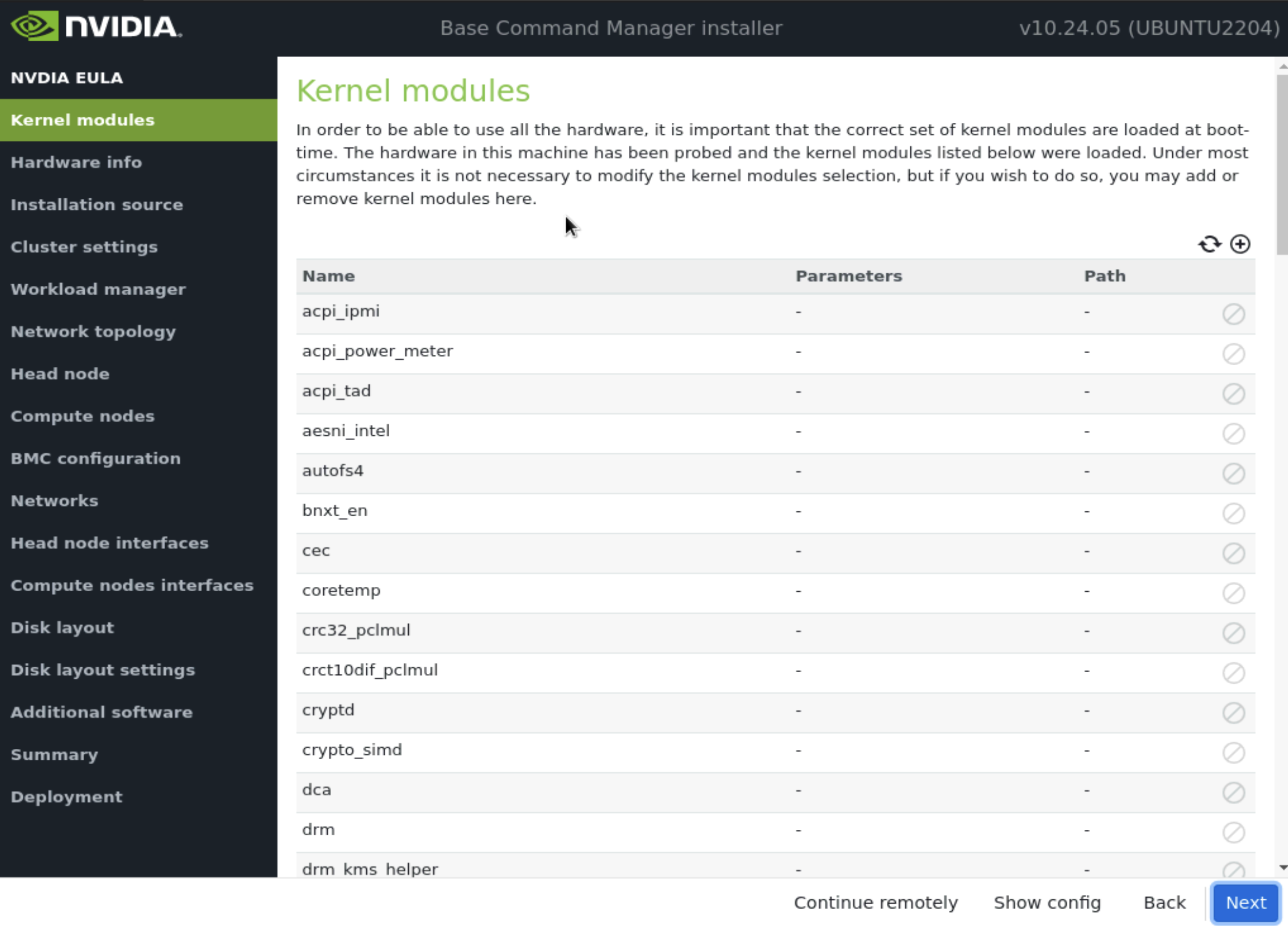
Unless instructed otherwise, select Next without modifying the kernel modules to be loaded at boot time.
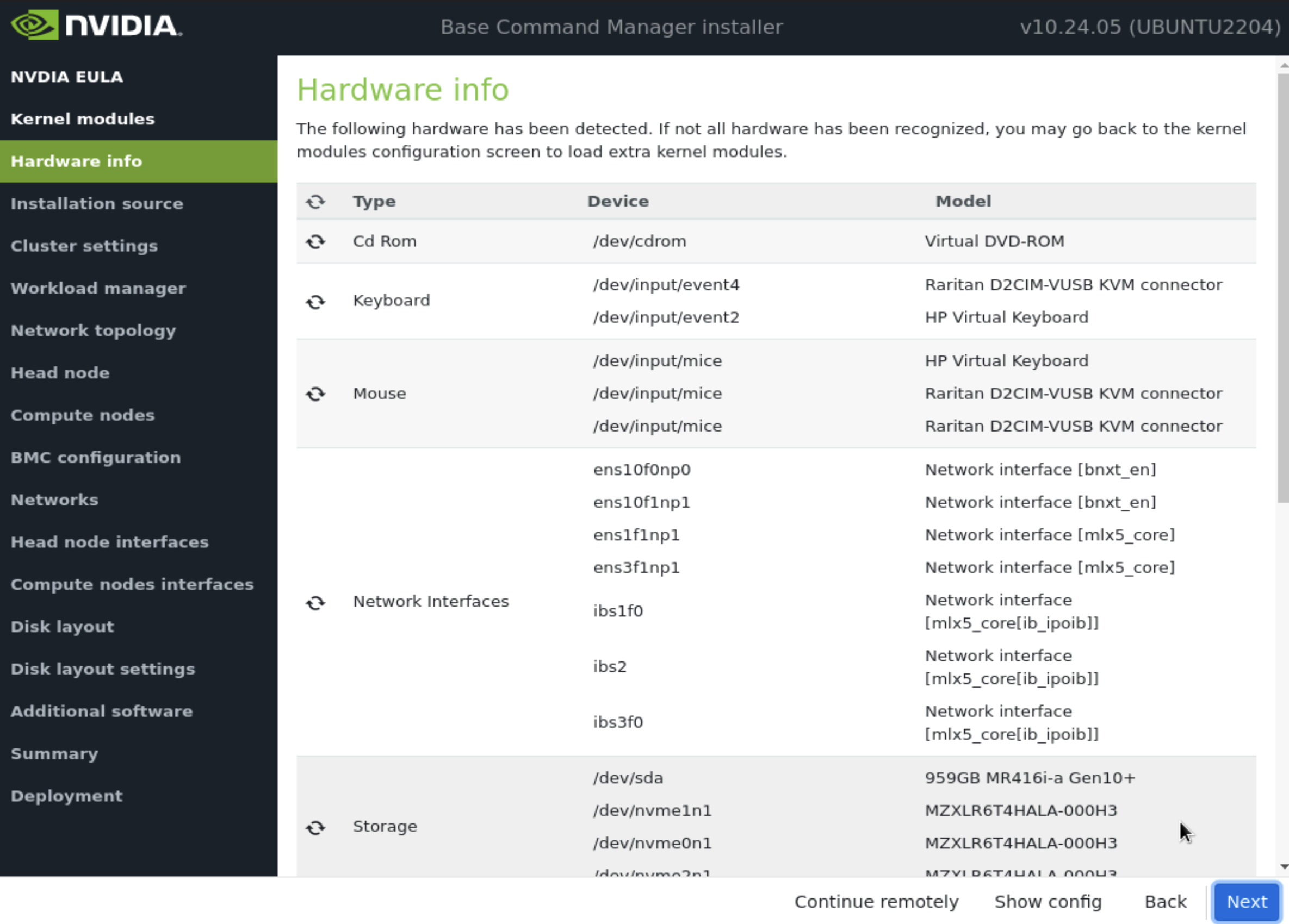
Verify the Hardware info is correct and then select Next.
For example, the target storage device and the cabled host network interfaces are present (in this case three NVMe drives are the target storage device, and ens1np0 and ens2np01 are the cabled host network interfaces).
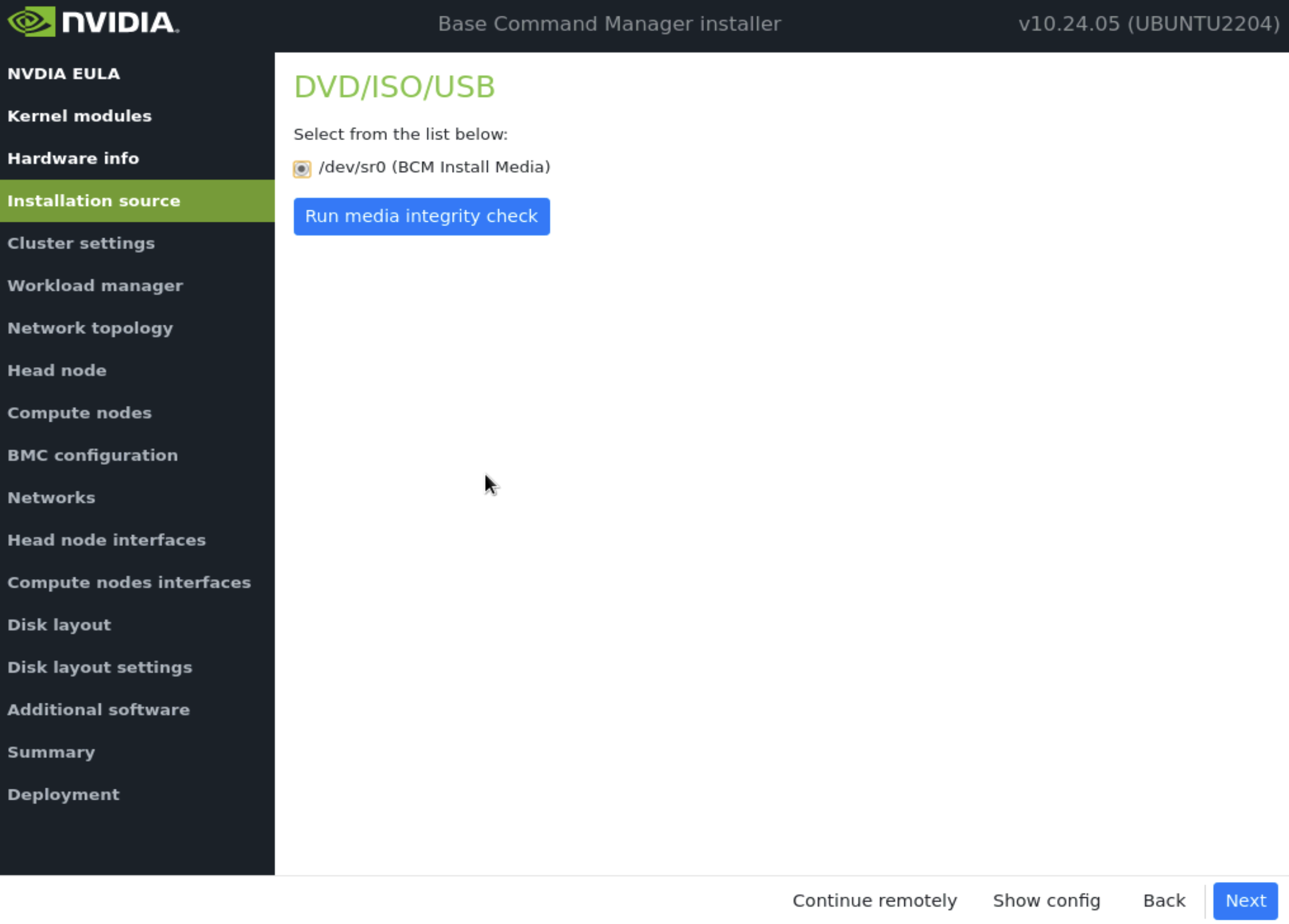
On the Installation source screen, choose the appropriate source and then select Next.
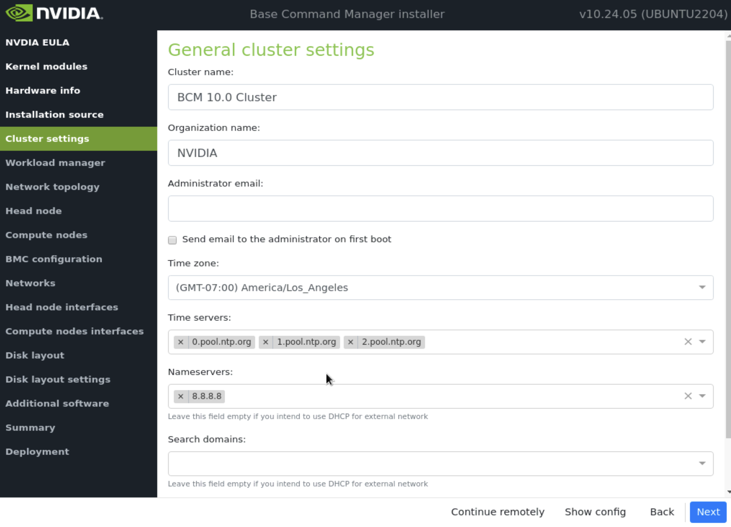
On the Cluster settings screen, enter the required information according to the site survey and then select Next.
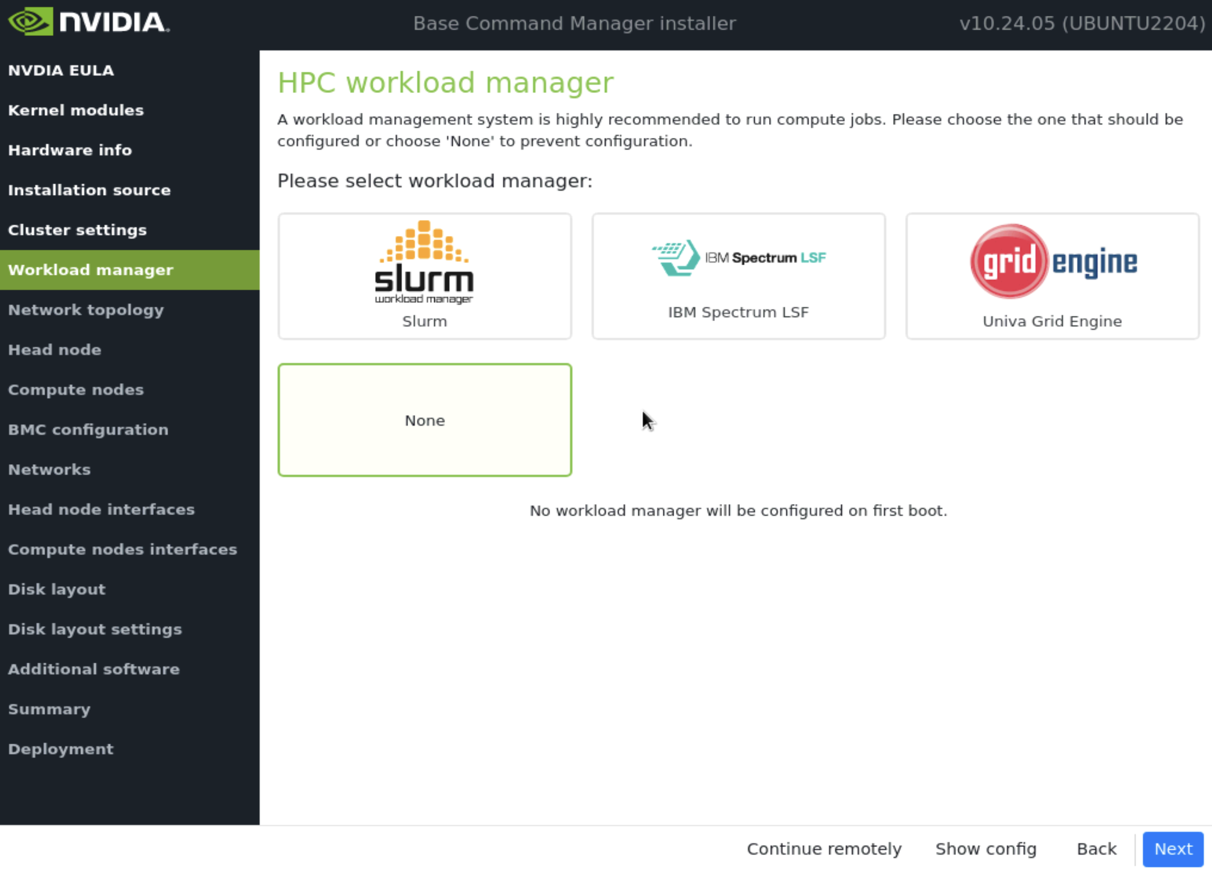
On the Workload manager screen, choose None and then select Next.
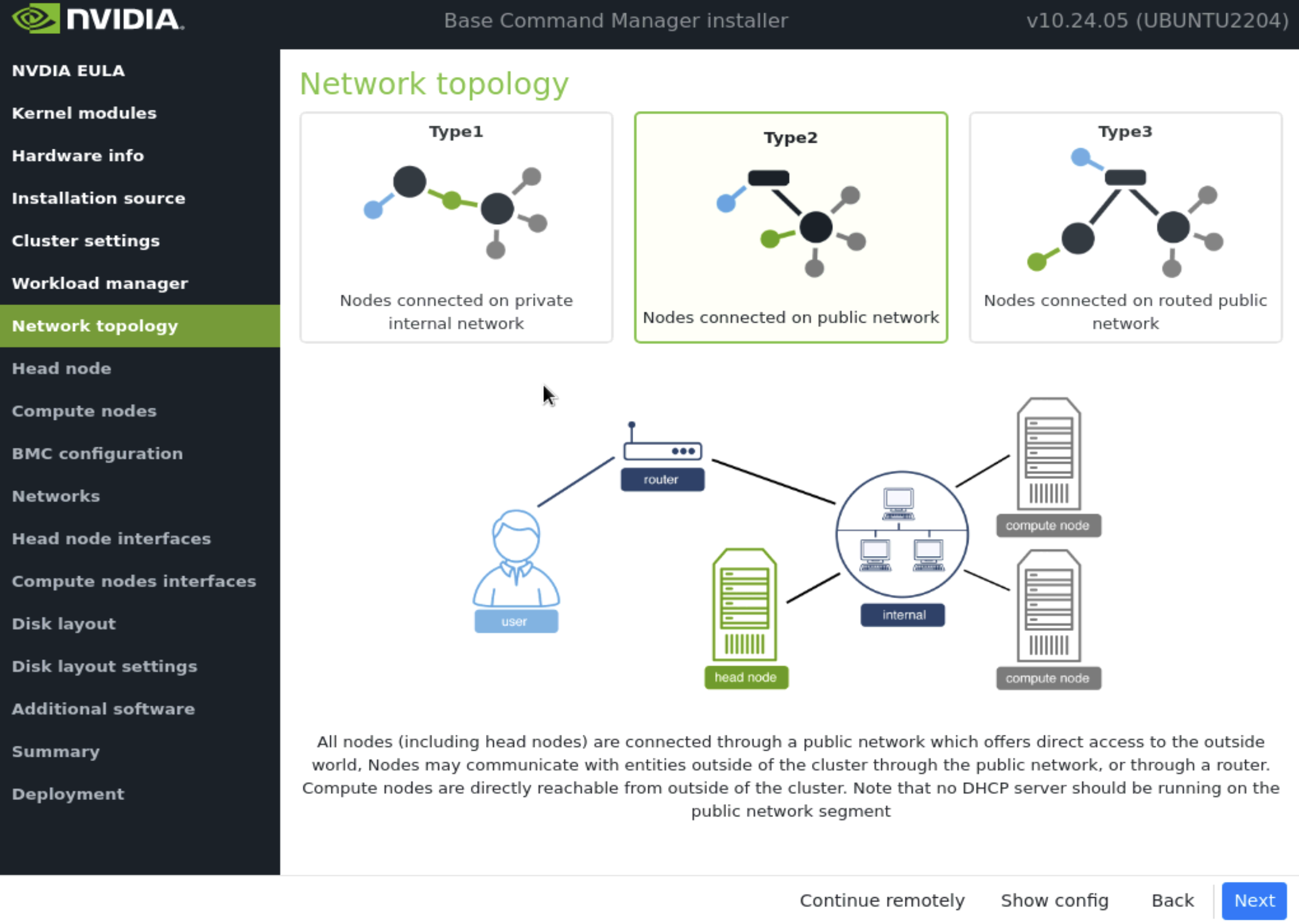
On the Network topology screen, choose the network type for the data center environment and then select Next.
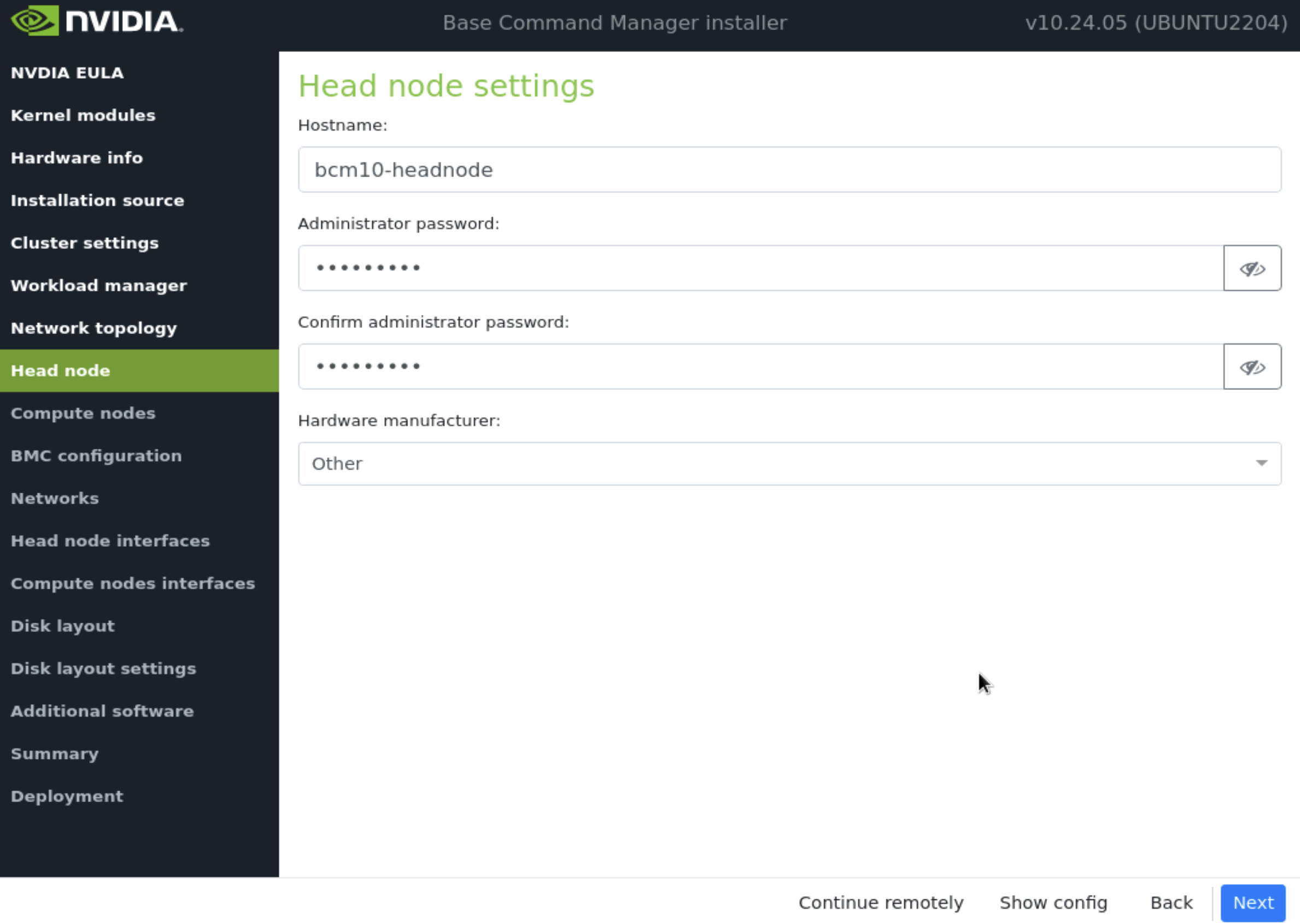
On the Head node screen, enter the Hostname, and Administrator password, choose Other for Hardware manufacturer, and then select Next.
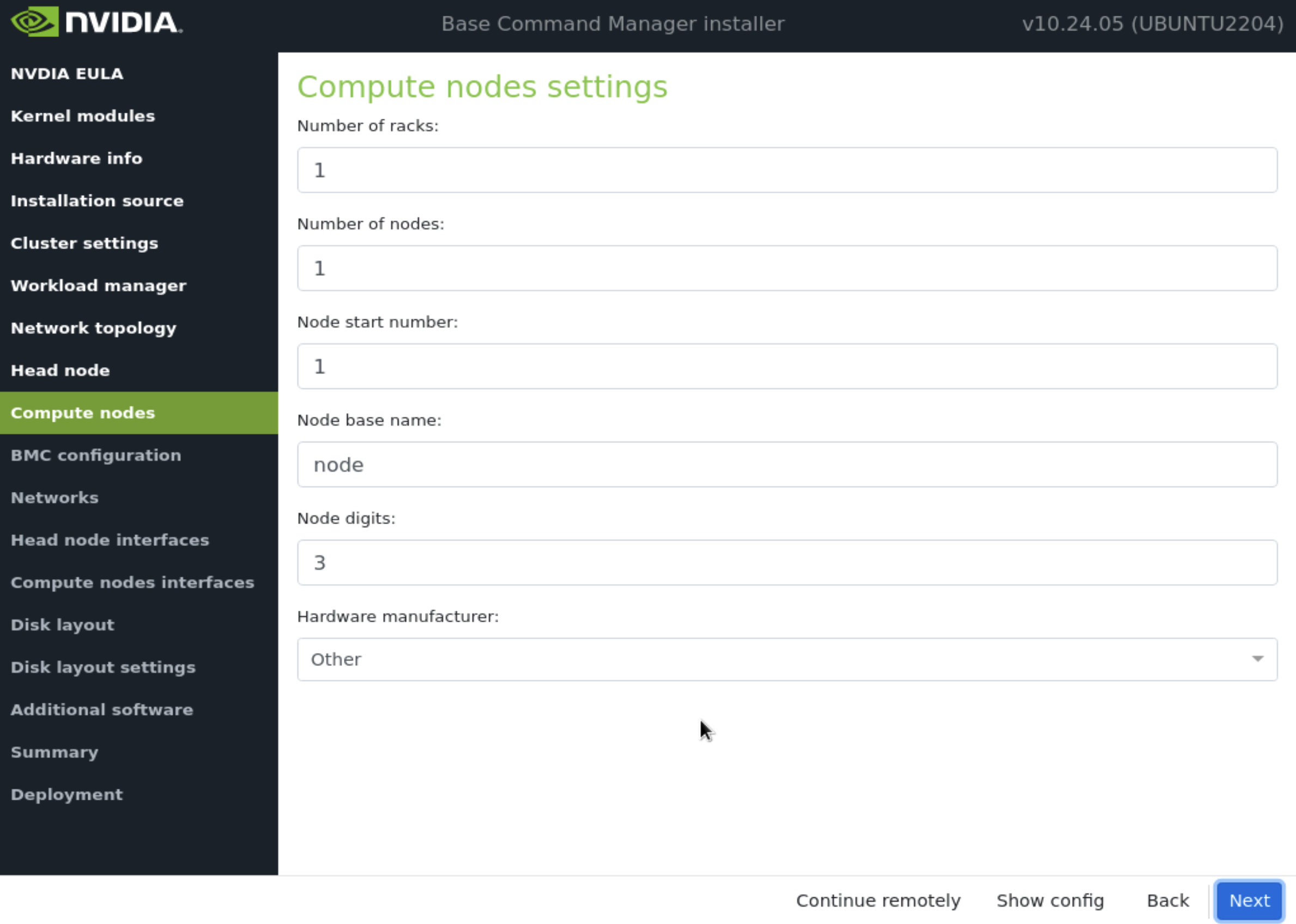
Accept defaults in the Compute nodes and then select Next. The values will be updated later in the installation.
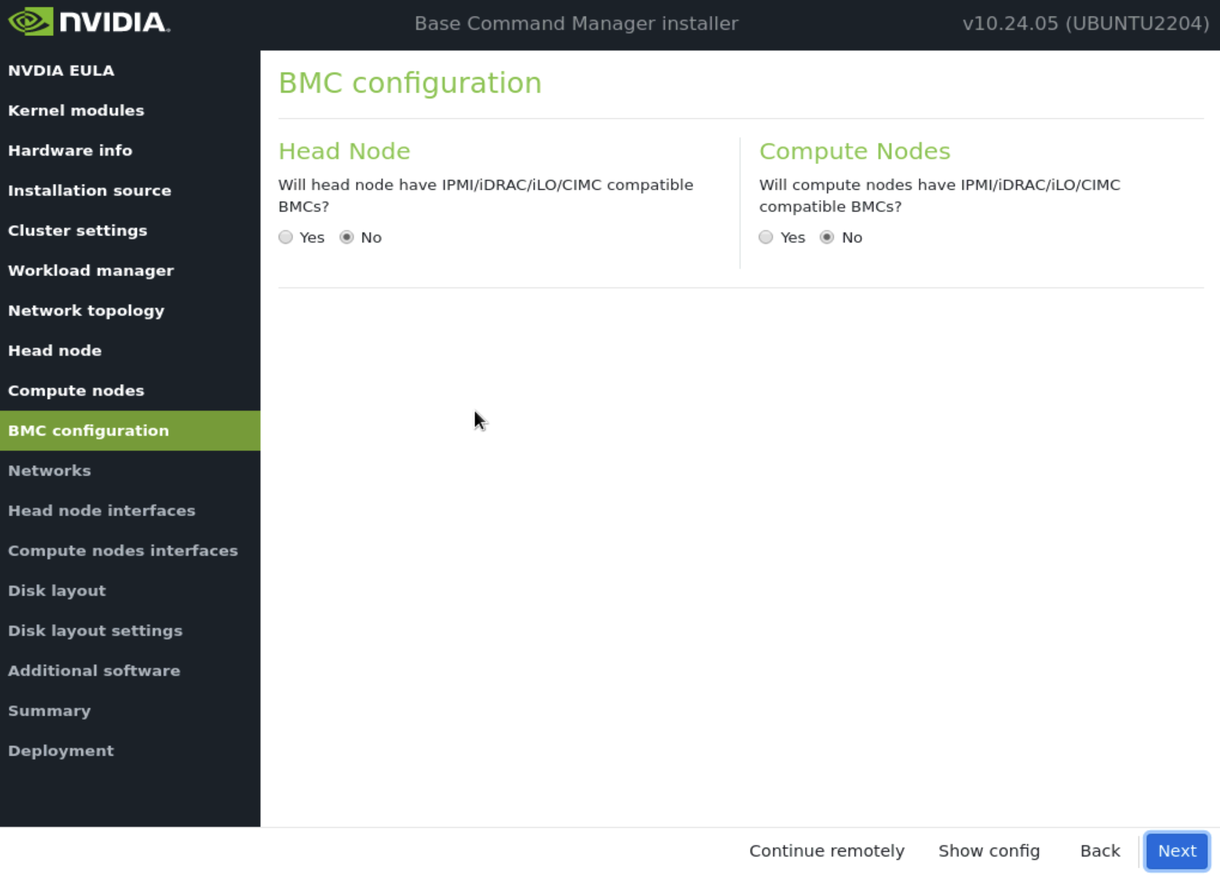
On the BMC Configuration screen, choose No for both Head Node and Compute Nodes, and then select Next.
These will be updated later in the post-install stages.
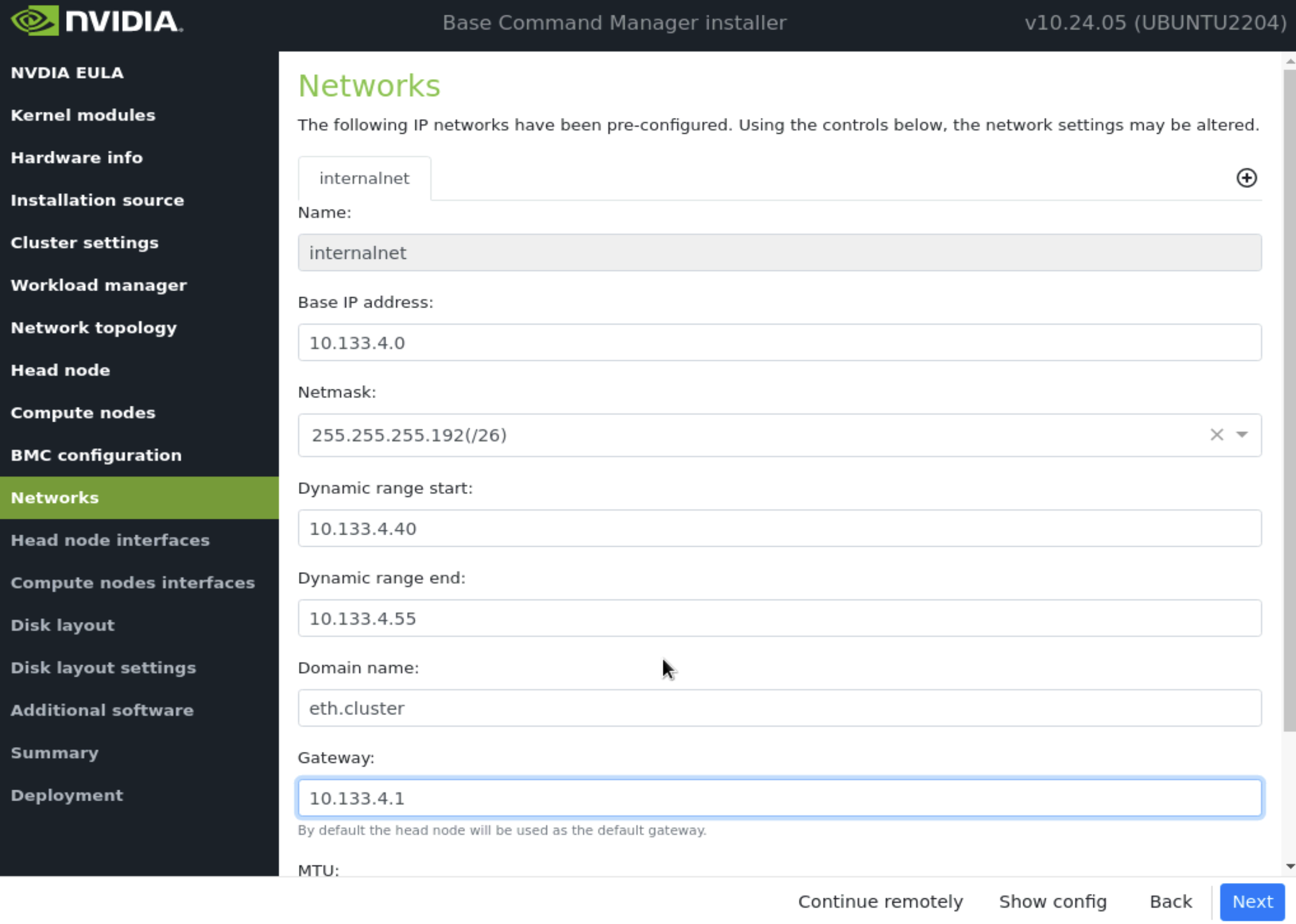
On the Networks screen, enter the required information for internalnet, and then select Next.
Since a Type 2 network was specified, there are no other network tabs (for example, internalnet or ipminet).
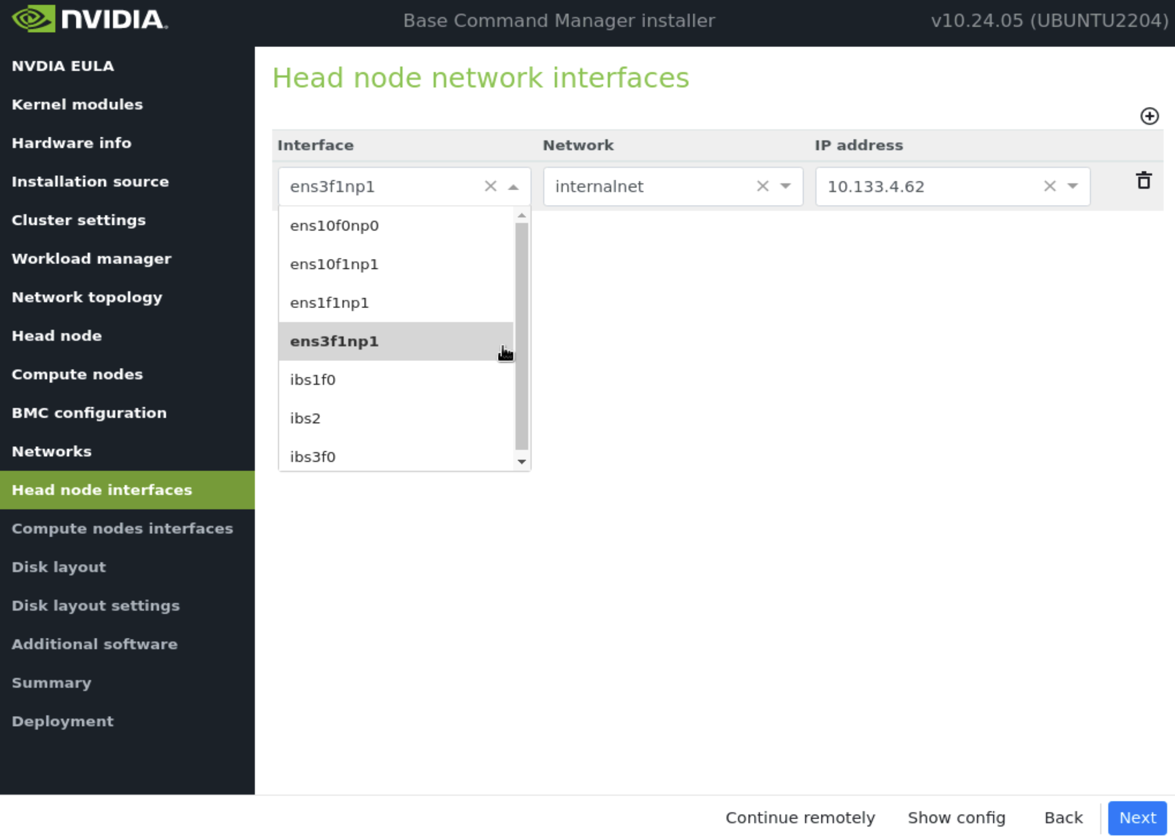
On the Head node interfaces screen, ensure that one interface is configured with the head node’s target internalnet IP, and then select Next.
Other interfaces will be configured by the post-install script. Ensure that the correct interface(s) is being configured.
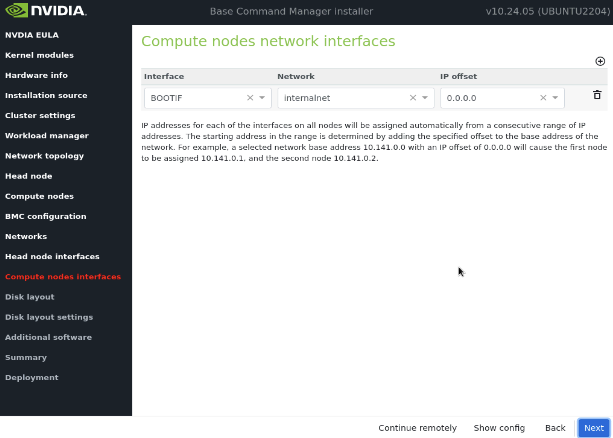
On the Compute node interfaces screen, leave the default entries, and then select Next.
These will be updated post-installation.
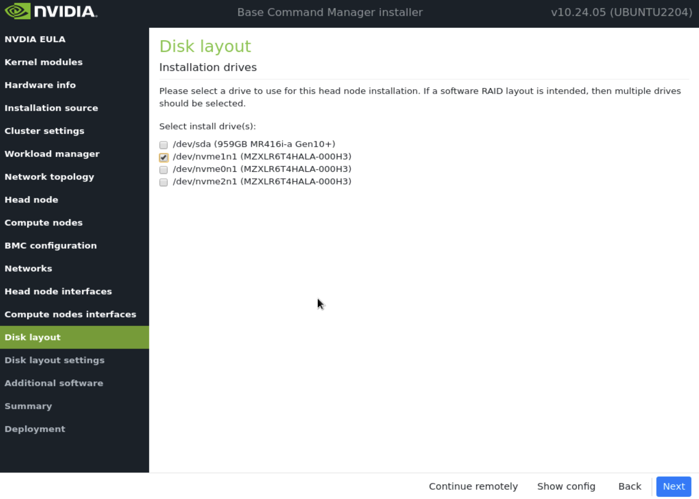
On the Disk layout screen, select the target install location (in this case nvme0n1) and then select Next.
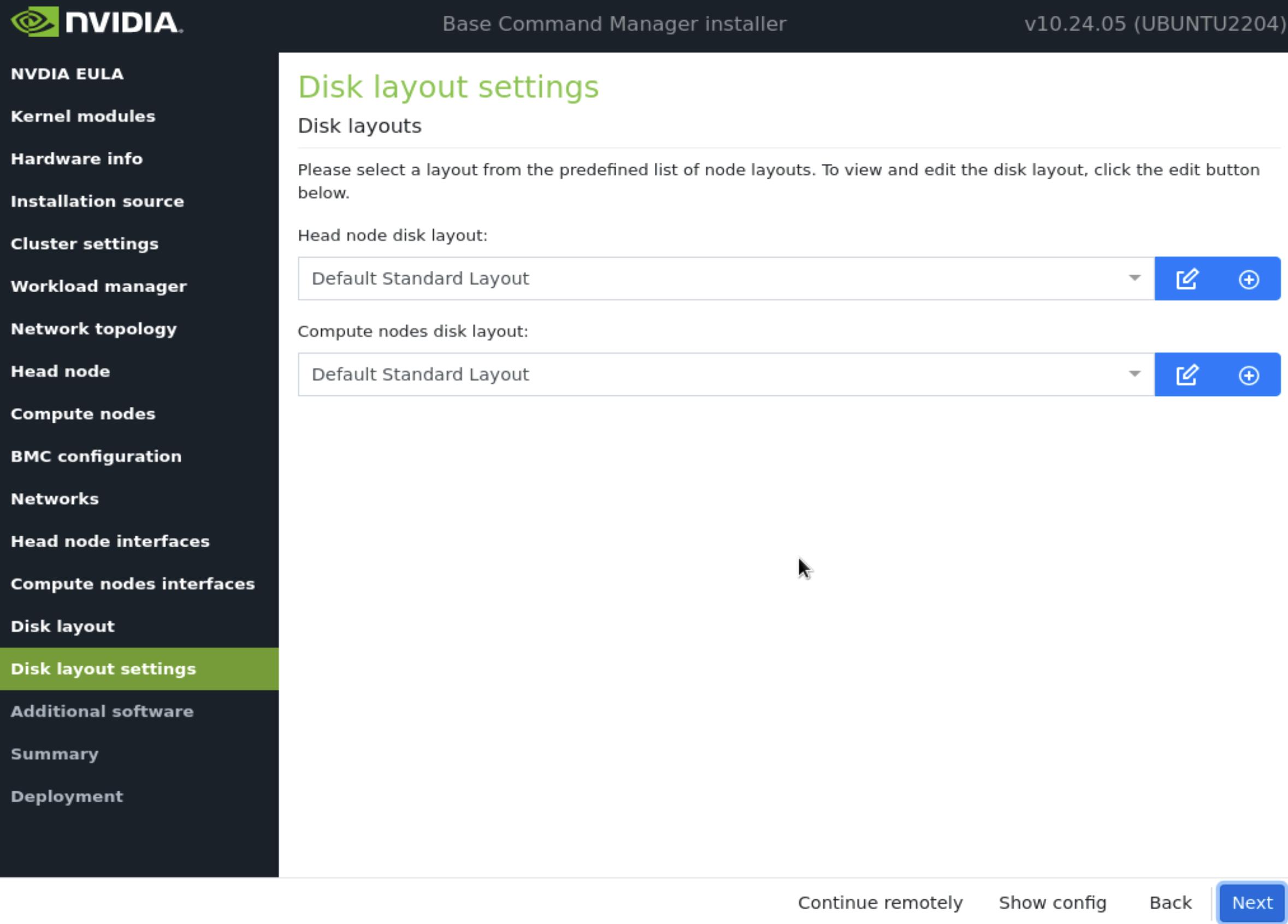
On the Disk layout settings screen, accept defaults and then select Next.
These settings will be updated later in the post-installation steps.
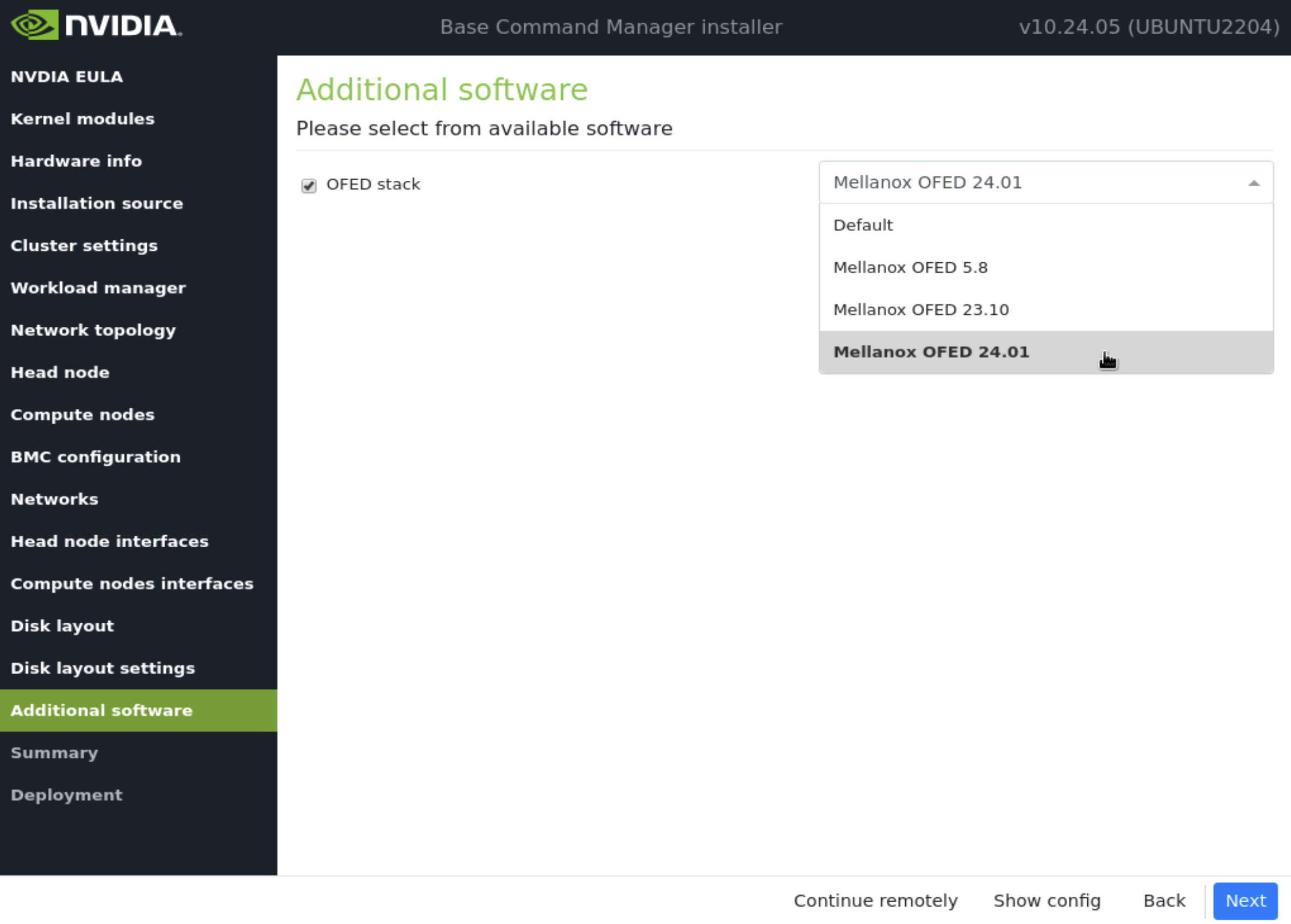
In the Additional software screen, select the newest version of OFED that is compatible with the DGX H100 and select Next.
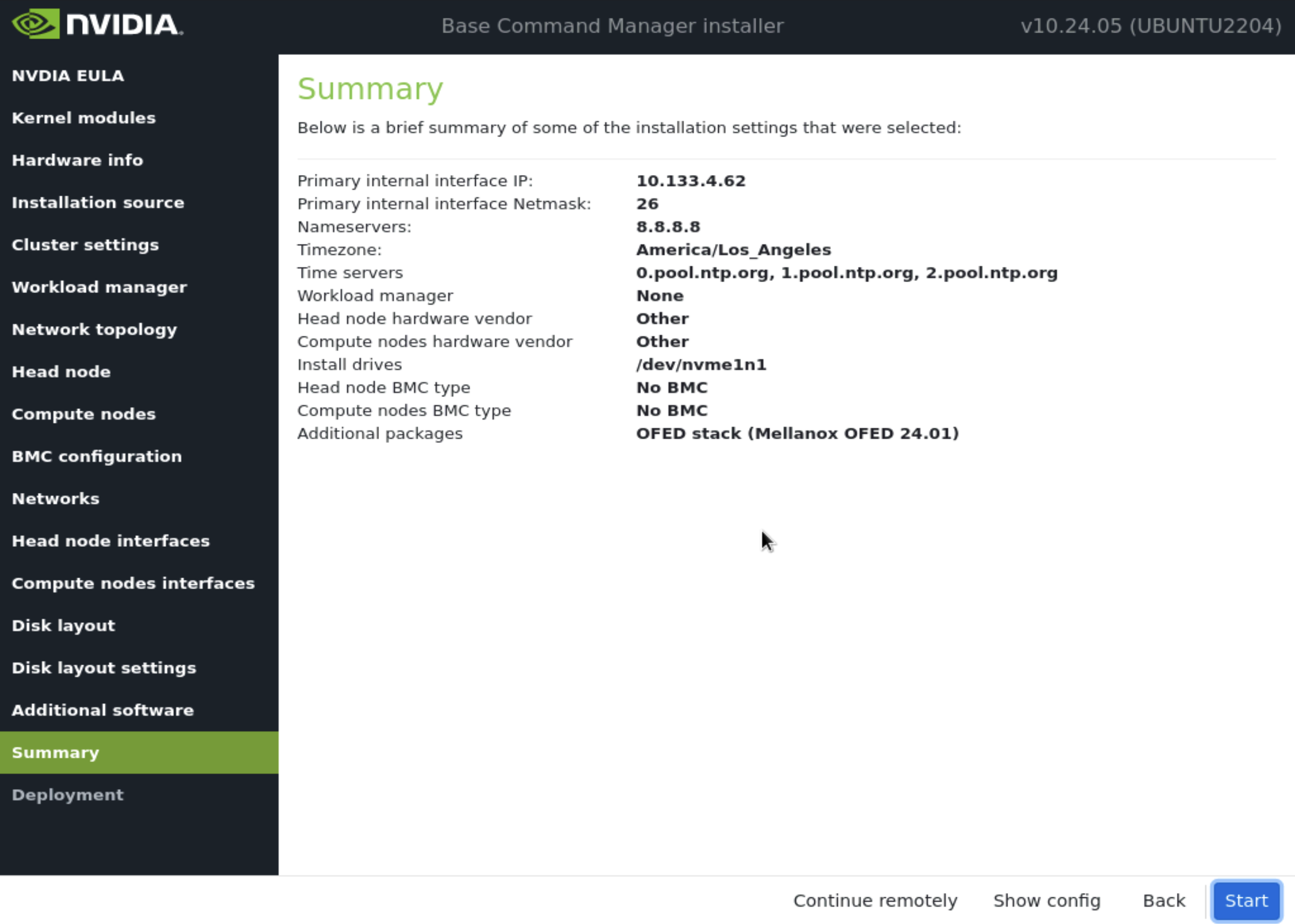
Confirm the information on the Summary screen and then select Next.
The Summary screen provides an opportunity to confirm the Head node and basic cluster configuration before deployment begins. This configuration will be updated/modified for DGX SuperPOD after deployment is complete. If values do not match expectations, use the Back button to navigate to the appropriate screen to correct any mistake.
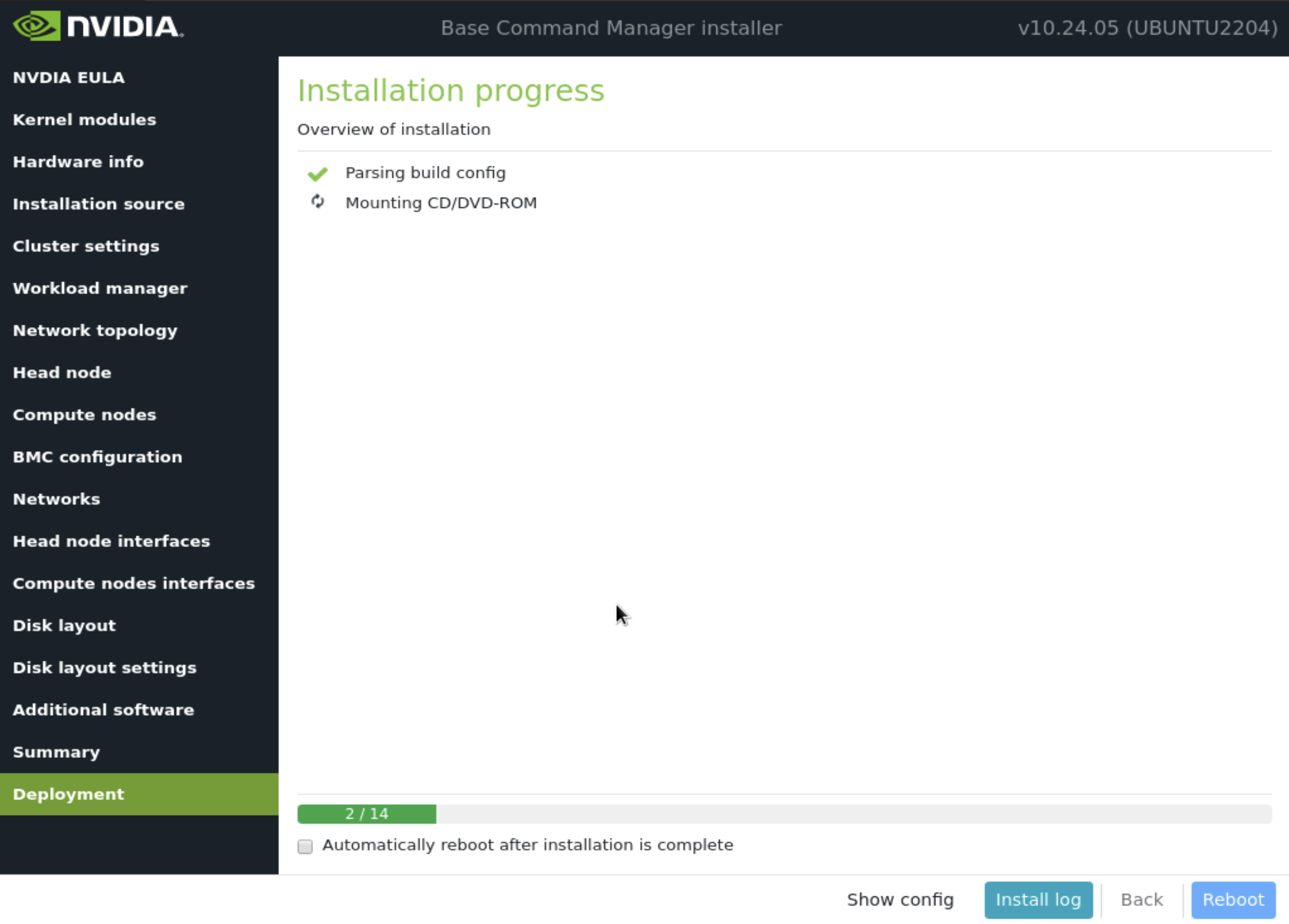
Once the deployment is complete, select Reboot.
Once the headnode has finished rebooting, ssh to it using the root credentials.
License the cluster by running the request-license command and providing the product key and other pieces of information.
request-license
Product Key (XXXXXX-XXXXXX-XXXXXX-XXXXXX-XXXXXX):
Country Name (2 letter code): US
State or Province Name (full name): California
Locality Name (e.g. city): Santa Clara
Organization Name (e.g. company): NVIDIA
Organizational Unit Name (e.g. department): Demo
Cluster Name: Demo Cluster
Private key data saved to /cm/local/apps/cmd/etc/cluster.key.new

Warning: Permanently added 'bcm10-headnode' (ED25519) to the list of known hosts.
MAC Address of primary head node (bcm10-headnode) for ens3f1np1 [08:C0:EB:F5:72:0F]:
If setting up a second headnode for HA, enter the mac address for it’s primary in-band interface.
Will this cluster use a high-availability setup with 2 head nodes? [y/N] y
MAC Address of secondary head node for eth0 [XX:XX:XX:XX:XX:XX]: 5c:6f:69:24:dd:54

Certificate request data saved to /cm/local/apps/cmd/etc/cluster.csr.new
Submit certificate request to http://licensing.brightcomputing.com/licensing/index.cgi ? [Y/n] Y

Contacting http://licensing.brightcomputing.com/licensing/index.cgi...

License granted.
License data was saved to /cm/local/apps/cmd/etc/cluster.pem.new
Install license? [Y/n] Y
========= Certificate Information ========
Version:                    10
Edition:                    Advanced
OEM:                        NVIDIA
Common name:                Demo Cluster
Organization:               NVIDIA
Organizational unit:        Demo
Locality:                   Santa Clara
State:                      California
Country:                    US
Serial:                     2369865
Starting date:              04/Oct/2023
Expiration date:            01/Sep/2024
MAC address / Cloud ID:     08:C0:EB:F5:72:0F|5C:6F:69:24:DD:54
Licensed tokens:            8192
Pay-per-use nodes:          Yes
Accounting & Reporting:     Yes
Allow edge sites:           Yes
License type:               Free
==========================================

Is the license information correct ? [Y/n] Y
Backup directory of old license: /var/spool/cmd/backup/certificates/2024-05-31_08.25.05
Installed new license
Revoke all existing cmd certificates

Waiting for CMDaemon to stop: OK

Installing admin certificates

Waiting for CMDaemon to start: OK
mysql: [Warning] Using a password on the command line interface can be insecure.
Copy cluster certificate to 3 images / node-installers
Copy cluster certificate to /cm/images/default-image//cm/local/apps/cmd/etc/cluster.pem
Copy cluster certificate to /cm/node-installer//cm/local/apps/cmd/etc/cluster.pem
Copy cluster certificate to /cm/images/dgx-os-6.1-h100-image//cm/local/apps/cmd/etc/cluster.pem
Copy cluster certificate to /cm/images/dgx-os-6.1-a100-image//cm/local/apps/cmd/etc/cluster.pem
mysql: [Warning] Using a password on the command line interface can be insecure.

Regenerating certificates for users

New license was installed. In order to allow compute nodes to obtain a new
node certificate, all compute nodes must be rebooted.

Please issue the following command to reboot all compute nodes:
    pdsh -g computenode reboot
Load the bcm-superpod-network module.
module load bcm-superpod-network
Run the bcm-netautogen script.
bcm-netautogen
Select Generate new network configuration and then H100. The rest can be set to the default option EXCEPT for the network segment for the cluster. Ensure that the subnet is at least a /22 and that the subnet for internalnet is contained within it.
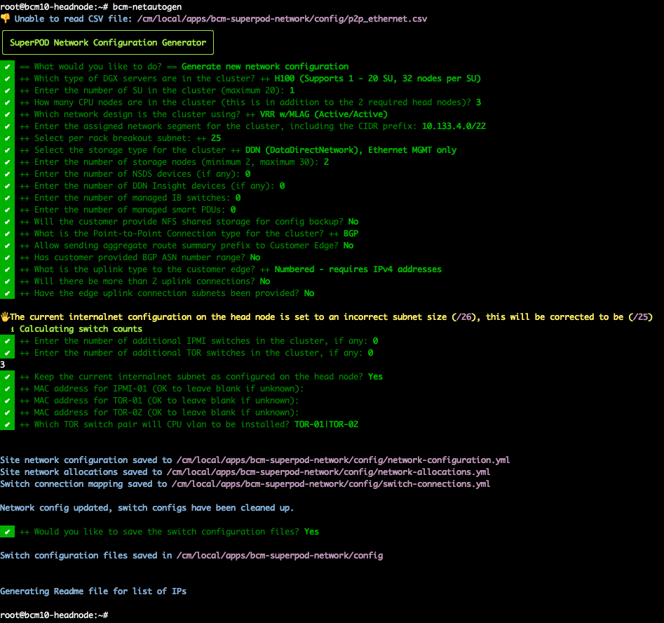
The following generated files are important and contain data:
Site network configuration - /cm/local/apps/bcm-superpod-network/config/network-configuration.yml
Site network allocations - /cm/local/apps/bcm-superpod-network/config/network-allocations.yml
Switch connection - /cm/local/apps/bcm-superpod-network/config/switch-connections.yml
IP Allocation Readme file - /cm/local/apps/bcm-superpod-network/config/ip_allocations.md
Download and move
cumulus-linux-5.5.1-mlx-amd64.binandimage-X86_64-3.11.2016.imgto the following directory on the head node. Contact your TAM for access to the correct file and move the file to the following directory on the head node.mv cumulus-linux-5.5.1-mlx-amd64.bin /cm/local/apps/cmd/etc/htdocs/switch/image/ mv image-X86_64-3.11.2016.img /cm/local/apps/cmd/etc/htdocs/switch/image/
Load the bcm-post-install module.
module load bcm-post-install/
Run the bcm-pod-setup script.
The parameters to use are:
–C sets the base address of the computenet network.
–S sets the base address of the storagenet network.
–I sets the installation source. (Can also be set to a copy of the iso used to install the headnode)
bcm-pod-setup -C 100.126.0.0/16 -S 100.127.0.0/16 -I /dev/sdb
Now that the base configuration has been created, enter cmsh to override the networks and ip addresses to align with the subnets allocated to the cluster.
cmsh
[bcm10-headnode->network]% ls
Name (key)         Type           Netmask bits   Base address     Domain name          IPv6
------------------ -------------- -------------- ---------------- -------------------- ----
computenet         Internal       16             100.126.0.0      ib.compute
dgxnet1            Internal       25             10.133.4.64      cm.dgx
globalnet          Global         0              0.0.0.0          cm.cluster
internalnet        Internal       25             10.133.4.0       eth.cluster
ipminet            Internal       25             10.133.6.0       cm.ipmi
loopback           Internal       25             10.133.7.128     cm.loopback
storagenet         Internal       16             100.127.0.0      ib.storage
Delete ipminet1 since it will not being used.
cmsh
[bcm10-headnode->network]% remove ipminet1
[bcm10-headnode->network*]% commit
Successfully removed 1 Networks
Successfully committed 0 Networks
Here is an example of changing dgxnet1 to a different subnet
cmsh
[bcm10-headnode->network]% set dgxnet1 baseaddress 10.133.5.0
[bcm10-headnode->network]% set dgxnet1 gateway 10.133.5.1
[bcm10-headnode->network]% set dgxnet1 netmaskbits 26
[bcm10-headnode->network*]% commit
Successfully committed 1 Networks