High Availability
Verify that the head node has power control over the cluster nodes.
1% device
2% power -c  dgx-h100 status
3[-head1->device]%  power -c  dgx-h100 status
4ipmi0 .................... [   ON    ]  bcm-dgx-h100-01
5ipmi0 .................... [   ON    ]  bcm-dgx-h100-02
6ipmi0 .................... [   ON    ]  bcm-dgx-h100-03
7ipmi0 .................... [   ON    ]  bcm-dgx-h100-04
8[bcm-head-01->device]%
Power off the cluster nodes.
The cluster nodes must be powered off before configuring HA.
1% power -c  dgx-h100 off
2ipmi0 .................... [   OFF   ] bcm-dgx-h100-01
3ipmi0 .................... [   OFF   ] bcm-dgx-h100-02
4ipmi0 .................... [   OFF   ] bcm-dgx-h100-03
5ipmi0 .................... [   OFF   ] bcm-dgx-h100-04
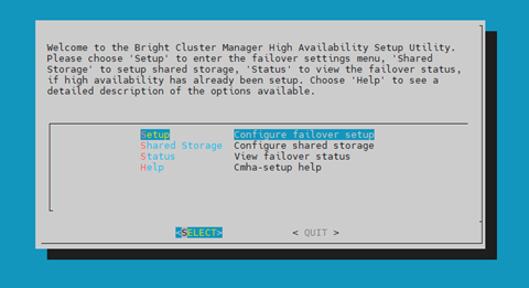
Start the cmha-setup CLI wizard as the root user on the primary head node.
# cmha-setupChoose Setup and then select SELECT.
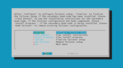
Choose Configure and then select NEXT.
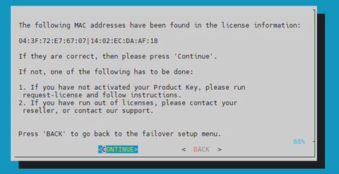
Verify that the cluster license information found cmha-setup is correct and then select CONTINUE.
Configure an external Virtual IP address that will be used by the active head node in the HA configuration and then select NEXT.
This will be the IP that should always be used for accessing the active head nodes.
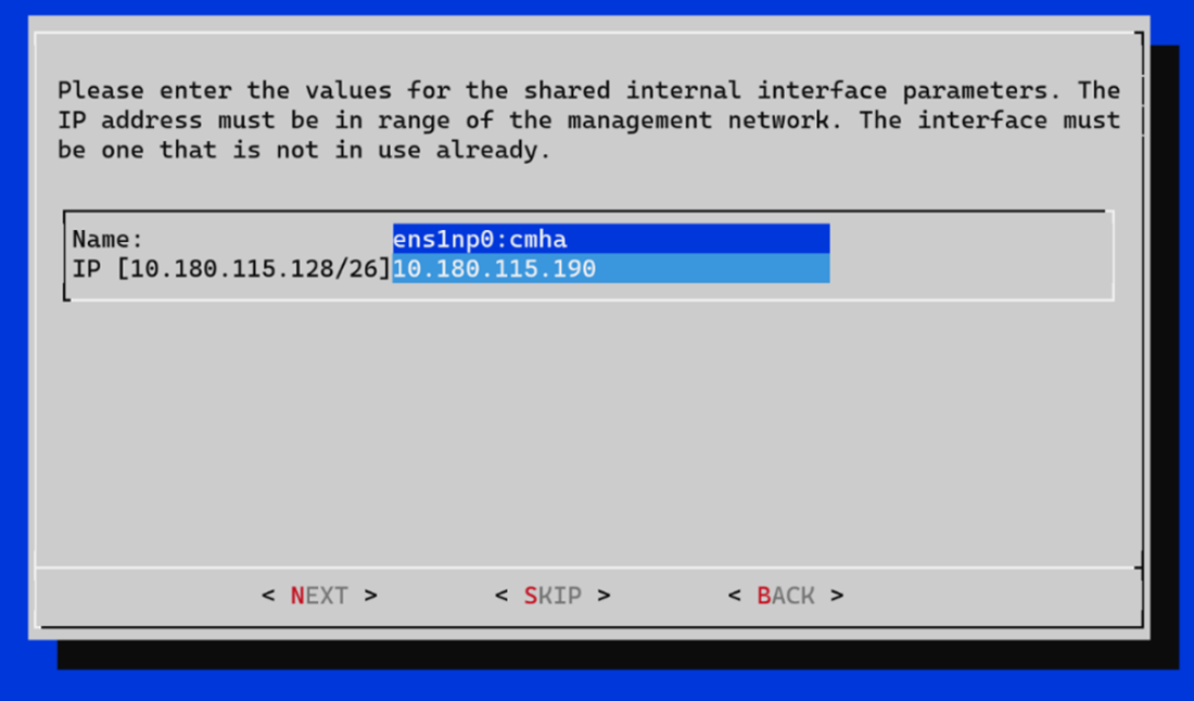
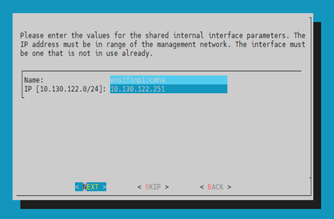
Provide an internal Virtual IP address that will be used by the active head node in the HA configuration.
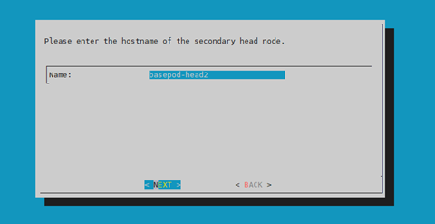
Provide the name of the secondary head node and then select NEXT.
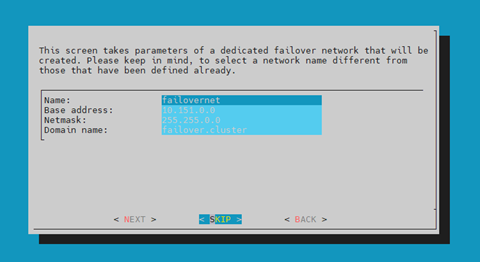
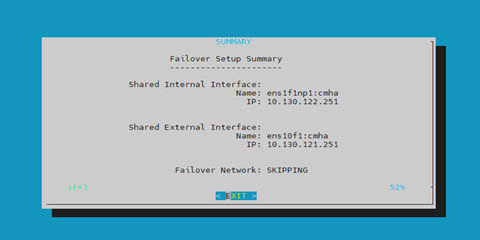
Because DGX SuperPOD uses the internal network as the failover network, select SKIP.
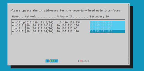
Configure the IP addresses for the secondary head node that the wizard is about to create and then select NEXT.
The wizard shows a summary of the information that it has collected. The VIP will be assigned to the internal and external interfaces, respectively.
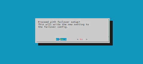
Select Yes to proceed with the failover configuration.
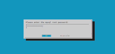
Enter the root password and then select OK.
The wizard implements the first steps in the HA configuration. If all the steps show OK, press ENTER to continue. The progress is shown here.
1Initializing failover setup on master.............. [  OK  ]
2Updating shared internal interface................. [  OK  ]
3Updating shared external interface................. [  OK  ]
4Updating extra shared internal interfaces.......... [  OK  ]
5Cloning head node.................................. [  OK  ]
6Updating secondary master interfaces............... [  OK  ]
7Updating Failover Object........................... [  OK  ]
8Restarting cmdaemon................................ [  OK  ]
9Press any key to continue
When the failover setup installation on the primary master is complete, select OK to exit the wizard.
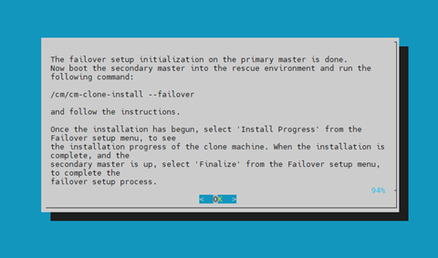
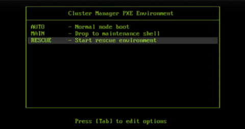
PXE boot the secondary head node and then select RESCUE from the grub menu.
Because this is the initial boot of this node, it must be done outside of Base Command Manager (BMC or physical power button).
Select RESCUE from the grub menu.
After the secondary head node has booted into the rescue environment, run the
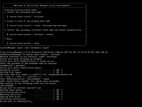
/cm/cm-clone-install --failovercommand, then enter YES when prompted.The secondary head node will be cloned from the primary.
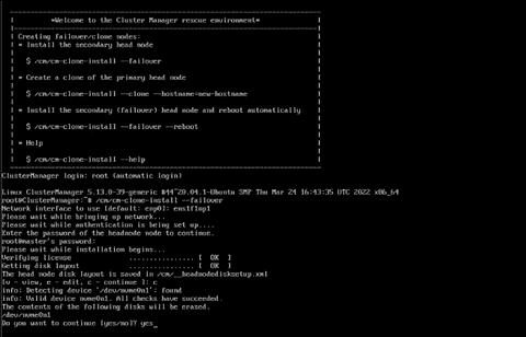
When cloning is completed, enter y to reboot the secondary head node.
The secondary must be set to boot from its hard drive. PXE boot should not be enabled.
Wait for the secondary head node to reboot and then continue the HA setup procedure on the primary head node.
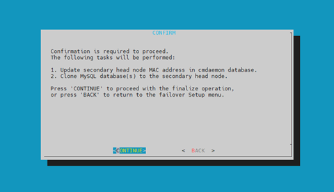
Select Finalize from the cmha-setup menu and then select NEXT.
This will clone the MySQL database from the primary to the secondary head node.
Select CONTINUE on the confirmation screen.
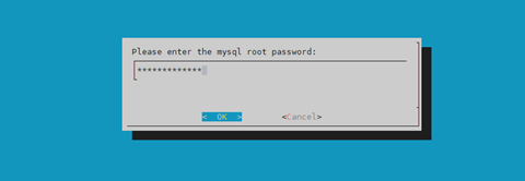
Enter the root password and then select OK.
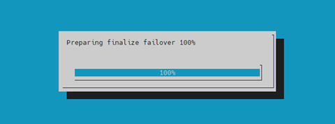
The cmha-setup wizard continues. Press ENTER to continue when prompted.
The progress is shown here:
 1Updating secondary master mac address.............. [  OK  ]
 2Initializing failover setup on bcm-head-02......... [  OK  ]
 3Stopping cmdaemon.................................. [  OK  ]
 4Cloning cmdaemon database.......................... [  OK  ]
 5Checking database consistency...................... [  OK  ]
 6Starting cmdaemon, chkconfig services.............. [  OK  ]
 7Cloning workload manager databases................. [  OK  ]
 8Cloning additional databases....................... [  OK  ]
 9Update DB permissions.............................. [  OK  ]
10Checking for dedicated failover network............ [  OK  ]
11Press any key to continue
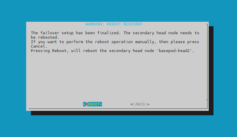
The Finalize step is now completed. Select REBOOT and wait for the secondary head node to reboot.
The secondary head node is now UP.
1% device list -f hostname:20,category:12,ip:20,status:15
2hostname (key)       category     ip                   status
3-------------------- ---------- -------------------- ---------------
4bcm-head-01                     10.130.122.254       [   UP   ]
5bcm-head-02                     10.130.122.253       [   UP   ]
6bcm-dgx-h100-01      dgx-h100   10.130.122.5         [  DOWN  ]
7bcm-dgx-h100-02      dgx-h100   10.130.122.6         [  DOWN  ]
8bcm-dgx-h100-03      dgx-h100   10.130.122.7         [  DOWN  ]
9bcm-dgx-h100-04      dgx-h100   10.130.122.8         [  DOWN  ]
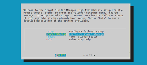
Select Shared Storage from the cmha-setup menu and then select SELECT.
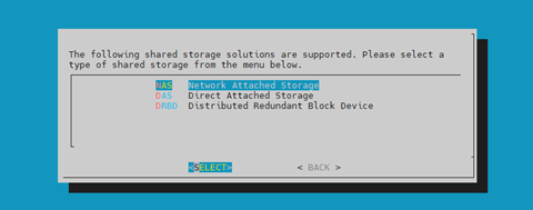
In this final HA configuration step, cmha-setup will copy the /cm/shared and /home directories to the shared storage and configure both head nodes and all cluster nodes to mount it.
Choose NAS and then select SELECT.
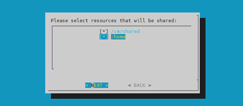
Choose both /cm/shared and /home and then select NEXT.
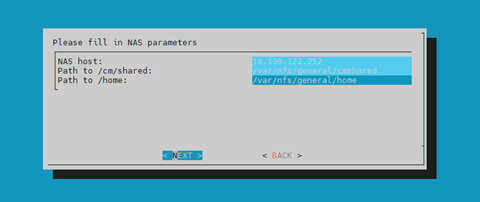
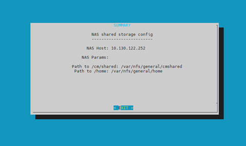
Provide the IP address of the NAS host, the paths that the /cm/shared and /home *directories should be copied to on the shared storage, and then select **NEXT*.
In this case, /var/nfs/general is exported, so the /cm/shared directory will be copied to 10.130.122.252:/var/nfs/general/cmshared, and it will be mounted over /cm/shared on the cluster nodes.
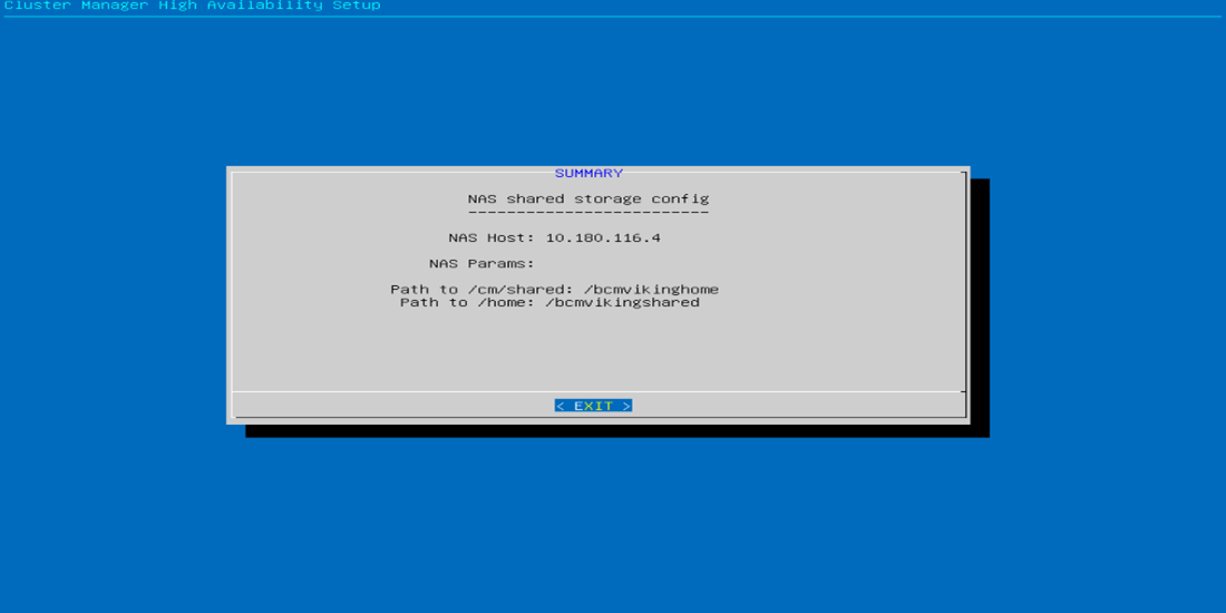
The wizard shows a summary of the information that it has collected. Select EXIT to continue.
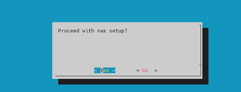
When asked to proceed with the NAS setup, select Yes to continue.
This will initiate a copy and update to fsexports.
The cmha-setup wizard proceeds with its work.
When setup completes, select ENTER to finish HA setup.
1The progress is shown here:
2Copying NAS data................................... [  OK  ]
3Mount NAS storage.................................. [  OK  ]
4Remove old fsmounts................................ [  OK  ]
5Add new fsmounts................................... [  OK  ]
6Remove old fsexports............................... [  OK  ]
7Write NAS mount/unmount scripts.................... [  OK  ]
8Copy mount/unmount scripts......................... [  OK  ]
9Press any key to continue
cmha-setup is now complete. EXIT the wizard to return to the shell prompt.
Run the
cmsh statuscommand to verify that the failover configuration is correct and working as expected.The command tests the configuration from both directions: from the primary head node to the secondary, and from the secondary to the primary. The active head node is indicated by an asterisk.
 1# cmha status
 2Node Status: running in active mode
 3
 4bcm-head-01* -> bcm-head-02
 5failoverping  [  OK  ]
 6mysql         [  OK  ]
 7ping          [  OK  ]
 8status        [  OK  ]
 9
10bcm-head-02 -> bcm-head-01*
11failoverping  [  OK  ]
12mysql         [  OK  ]
13ping          [  OK  ]
14status        [  OK  ]
Verify that the /cm/shared and /home directories are mounted from the NAS server.
1# mount
2. . . some output omitted . . .
310.130.122.252:/var/nfs/general/cmshared on /cm/shared type nfs4 (rw,relatime,vers=4.2,rsize=32768,wsize=32768,namlen=255,hard,proto=tcp,timeo=600,retrans=2,sec=sys,clientaddr=10.130.122.253,local_lock=none,addr=10.130.122.252)
410.130.122.252:/var/nfs/general/home on /home type nfs4 (rw,relatime,vers=4.2,rsize=32768,wsize=32768,namlen=255,hard,proto=tcp,timeo=600,retrans=2,sec=sys,clientaddr=10.130.122.253,local_lock=none,addr=10.130.122.252)
Login to the head node to be made active and run
cmha makeactive.1# ssh bcm-head-02 2# cmha makeactive 3========================================================================= 4This is the passive head node. Please confirm that this node should become 5the active head node. After this operation is complete, the HA status of 6the head nodes will be as follows: 7 8bcm-head-02 will become active head node (current state: passive) 9bcm-head-01 will become passive head node (current state: active) 10========================================================================= 11 12Continue(c)/Exit(e)? c 13 14Initiating failover.............................. [ OK ] 15 16bcm-head-02 is now active head node, makeactive successful
Run the
cmsh statuscommand again to verify that the secondary head node has become the active head node.1# cmha status 2Node Status: running in active mode 3 4bcm-head-02* -> bcm-head-01 5failoverping [ OK ] 6mysql [ OK ] 7ping [ OK ] 8status [ OK ] 9 10bcm-head-01 -> bcm-head-02* 11failoverping [ OK ] 12mysql [ OK ] 13ping [ OK ] 14status [ OK ]
Manually failover back to the primary head node by running
cmha makeactive.1# ssh bcm-head-01 2# cmha makeactive 3 4=========================================================================== 5This is the passive head node. Please confirm that this node should become 6the active head node. After this operation is complete, the HA status of 7the head nodes will be as follows: 8 9bcm-head-01 will become active head node (current state: passive) 10bcm-head-02 will become passive head node (current state: active) 11=========================================================================== 12 13Continue(c)/Exit(e)? c 14 15Initiating failover.............................. [ OK ] 16 17bcm-head-01 is now active head node, makeactive successful
Run the
cmsh statuscommand again to verify that the primary head node has become the active head node.1# cmha status 2Node Status: running in active mode 3 4bcm-head-01* -> bcm-head-02 5failoverping [ OK ] 6mysql [ OK ] 7ping [ OK ] 8status [ OK ] 9 10bcm-head-02 -> bcm-head-01* 11failoverping [ OK ] 12mysql [ OK ] 13ping [ OK ] 14status [ OK ]
Power on the cluster nodes.
1#  cmsh -c "device ; power -c  dgx-h100 on"
2ipmi0 .................... [   ON    ] bcm-dgx-h100-01
3ipmi0 .................... [   ON    ] bcm-dgx-h100-02
4ipmi0 .................... [   ON    ] bcm-dgx-h100-03
5ipmi0 .................... [   ON    ] bcm-dgx-h100-04
This concludes the setup and verification of HA.