


ConnectX-7 Networking#
Connecting DGX Spark Systems into a Cluster#
Overview#
You can connect multiple DGX Spark systems with cables to create a cluster that allows you to run workloads that cannot fit onto a single device.
At the highest level, clustering DGX Spark devices requires you to:
Physically connect them with Quad Small Form-factor Pluggable (QSFP) cables plugged into the external QSFP ports.
Detect the network interfaces that need IP addresses for inter-device communication.
Set up the IP layer to route traffic to those interfaces.
Step one is straightforward, as described in QSFP Ports and Cables. However, step two can be confusing if you are unfamiliar with the unique PCIe topology of the DGX Spark. That confusion can lead to mistakes in step three and prevent the cluster from working correctly.
This section introduces the details needed to understand the basics of clustering the devices without doing a full PCIe deep dive.
If you just need a quick reference, skip to the Full Correspondence Table.
The QSFP Ports and Cables#
QSFP technology is a compact, hot-swappable, and bidirectional transceiver for high-speed data transfer. Each DGX Spark has two QSFP ports (sometimes called “ConnectX-7 ports”) on the back of the device. Each port provides up to 200 Gigabits per second (Gb/s), but the incoming speed is also determined by the cable that you use.
QSFP cables come in different generations and speeds:
Use cables that are known to provide at least 200 Gb/s.
Using a cable with higher speed is not beneficial, because the port itself is capped at 200 Gb/s.
Note
The QSFP ports support Ethernet configuration only. Approved cables are:
Amphenol: NJAAKK-N911 (QSFP to QSFP112, 32AWG, 400mm, LSZH), NJAAKK0006 is the 0.5m version of this cable
Luxshare: LMTQF022-SD-R (QSFP112 400G DAC Cable, 400mm, 30AWG)
Plugging in a QSFP Cable#
When it comes to plugging in the cables, the QSFP ports are interchangeable. However, the current clustering playbooks (Connect Two Sparks, Connect Three Sparks, and Multi Sparks Through a Switch) assume certain ports. Therefore, it is important to know the left port from the right port.
When seen from the back of the device, the left port is the QSFP port closest to the ethernet port. To contrast this, in the figure below the cable is plugged into the right port.
To properly plug a QSFP cable into a port, complete the following steps:
Turn the DGX Spark so that the back is facing you with the ports exposed.
Select one of the two QSFP ports.
Orient the cable so the pull-tab (sometimes called a “ring tab”) faces upward. This is shown in the right port of the figure below.
Plug the cable into the selected port. It should slide in smoothly without force. If that is not happening, make sure the pull-tab is facing up.
Make sure the cable is fully inserted.
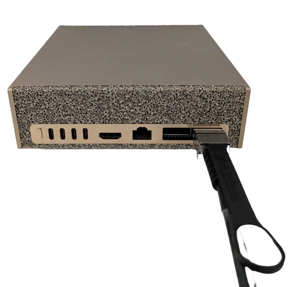
Warning
Do not force the QSFP cable into the port. If it does not slide in smoothly, stop, verify tab orientation and port alignment, and try again. Forcing an upside-down or misaligned connector can damage the port.
Removing the QSFP Cable#
You can remove the cable by pulling the pull-tab. Its should come out easily.
Understand the ConnectX-7 Network#
The QSFP ports are connected to the high-bandwidth ConnectX-7 network interface controller (NIC) in the DGX Spark. The NIC is the heart of high-speed inter-device communication between connected DGX Spark systems.
Keep the following high-level facts in mind:
The NIC sits between the external QSFP ports and the Grace Blackwell system on a chip (SoC).
The NIC connects independently to the two external QSFP ports, and it connects to the SoC through two independent PCIe Gen 5 x4 links.
As a result, each QSFP port has two PCIe addresses to account for the two PCIe x4 links out of the NIC into the SoC.
These facts imply the following Linux network configuration details:
Each QSFP port appears as two independent Linux Ethernet interfaces. As a result, plugging in two cables shows a total of four Linux Ethernet interfaces.
Each Ethernet interface has a corresponding RoCE interface (typically called a “RoCE device”) for InfiniBand communication.
Interface Names and PCIe Addresses#
When you plug a QSFP cable into the back of a DGX Spark, Linux automatically creates four network interface names in order to give the two PCIe addresses in the port their own unique Ethernet and RoCe names. If you plug in two cables, then you double the number to get a total of eight unique network interfaces.
Linux builds the names from the PCIe addresses, and so the interface names are the same on all DGX Spark devices. However, they are difficult to understand without knowing the naming pattern. This section explains the pattern using the ibdev2netdev command for a DGX Spark with cables in both QSFP ports.
The following output shows the eight network interface names for the two QSFP ports, with four RoCE on the left and four Ethernet on the right:
nvidia@spark-1afa:~$ ibdev2netdev
rocep1s0f0   port 1 ==> enp1s0f0np0   (Up)
rocep1s0f1   port 1 ==> enp1s0f1np1   (Up)
roceP2p1s0f0 port 1 ==> enP2p1s0f0np0 (Up)
roceP2p1s0f1 port 1 ==> enP2p1s0f1np1 (Up)
Looking across a single row, you can see that the central characters of both names are a shared PCIe address. For example, both sides of row 1 share p1s0f0, and both sides of row 3 share P2p1s0f0.
The other characters in the names are just there to differentiate RoCe versus Ethernet, as well as specify the interface ports. For example:
roce(RoCE) on the left anden(“Ethernet”) distinguish the types.On the Ethernet side,
np0andnp1designate the Ethernet network ports.On the RoCE side,
port 1designates the RoCE port.
Differentiating the PCIe addresses is a bit more complicated but can be done by splitting them into individual fields as show below:
Row |
PCIe Domain |
Bus |
Slot |
Function |
|---|---|---|---|---|
1 |
blank |
p1 |
s0 |
f0 |
2 |
blank |
p1 |
s0 |
f1 |
3 |
P2 |
p1 |
s0 |
f0 |
4 |
P2 |
p1 |
s0 |
f1 |
Note the following about this table of split PCIe addresses:
The PCIe domain of rows 1 and 2 is actually
0, but it is omitted by convention and so is blank.The PCIe domain of rows 3 and 4 is
2. It is included to avoid conflation with the previous convention for0.Moving left to right specifies the address corresponding to outputs of the
lspcicommand.
With this vocabulary and convention, you can read row 1 of the ibdev2netdev command as follows:
“The RoCE interface at PCIe domain 0, bus 1, slot 0, function 0, and RoCE port 1 corresponds to the Ethernet interface at PCIe domain 0, bus 1, slot 0, function 0, and network port 0.”
A similar statement for row 4 of the command output is:
“The RoCE interface at PCIe domain 2, bus 1, slot 0, function 1, and RoCE port 1 corresponds to the Ethernet interface at PCIe domain 2, bus 1, slot 0, function 1, and network port 1.”
Full Correspondence Table#
The following table shows the correspondences between the QSFP ports and relevant addresses:
QSFP Port |
Port # |
PCIe Address |
Ethernet Address |
RoCE Address |
|---|---|---|---|---|
Left |
|
|
|
|
Left |
|
|
|
|
Right |
|
|
|
|
Right |
|
|
|
|
Next Steps#
Cluster with NVIDIA Sync#
The NVIDIA Sync Cluster Assistant provides a guided way to configure a supported DGX Spark cluster. It does automatic discovery and network creation to eliminate the network configuration you would typically do manually in a terminal.
The Cluster Assistant validates the devices, applies ConnectX-7 network settings, checks link performance, and configures SSH between nodes. It supports up to three DGX Spark systems connected directly through cables, and up to four systems when using a switch.
For NVIDIA Sync installation and the Cluster Assistant workflow, refer to the NVIDIA Sync User Guide.
Playbooks to Connect Multiple DGX Sparks#
For manual configuration using playbooks, refer to the following connection options: