Camera-over-Ethernet Overview#
Camera-over-Ethernet (CoE) is NVIDIA’s next-generation camera connectivity solution, enabling high-performance, flexible, and scalable camera integration using standard Ethernet networks.
CoE is fully supported in the Safe Image Processing Library (SIPL) framework, which provides a unified API and driver model to support seamless bring-up of Holoscan Sensor Bridge (HSB)–based cameras.
To learn more about the SIPL framework, refer to Introduction to SIPL.
CoE as a Replacement for VI and NVCSI#
CoE is designed as a new camera solution with an Ethernet-based camera data path that replaces the traditional Video Input (VI) and NVIDIA Camera Serial Interface (NVCSI) blocks.
Instead of using point-to-point MIPI CSI connections, CoE uses standard Ethernet infrastructure such as the MGBE controller on the Jetson AGX Thor Developer Kit board and the IEEE 1722b protocol to receive camera data.
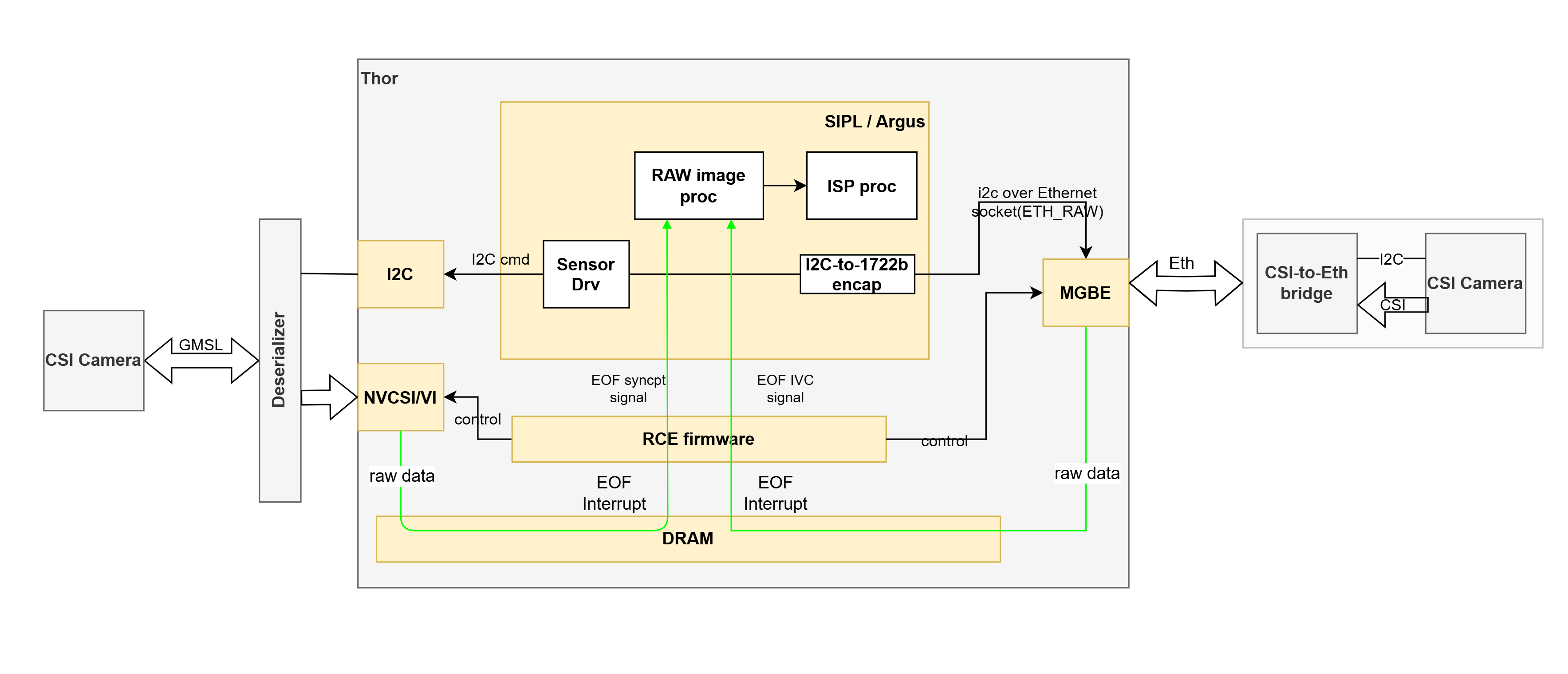
CoE vs GMSL/MIPI CSI architecture#
CoE is supported with Holoscan Sensor Bridge (HSB), which connects camera sensors to the Ethernet network (MGBE controller) on the Jetson AGX Thor Developer Kit board. With this release package, the Eagle camera (VB1940 with HSB) is supported out of the box.
MIPI and GMSL cameras, interfaced with HSB (that is, the CSI2Eth bridge) can also be supported through CoE architecture and SIPL framework.
For more details on HSB, refer to Holoscan Sensor Bridge.
For more details on how to work with the Eagle camera (VB1940) or other HSB-based cameras, refer to the appropriate sections in the HSB documentation.
Key Points
Raw image data is received by the Ethernet PHY (MGBE) for CoE.
From the SIPL perspective, the transport is abstracted. Although only CoE transport is supported now, applications would use the same SIPL APIs across CoE and non-CoE transports in future development.
For the Camera userspace stack, there is no difference between a RAW image received from VI-NVCSI or CoE-MGBE; both are placed in DRAM buffers, provided by the application for downstream processing, such as ISP.
Use Cases
Industrial and robotics vision with long cable runs.
Smart city and surveillance camera networks.
Flexible, scalable multi-camera platforms.
Advantages
Scalability and modularity (multiple cameras on a shared network).
Data integrity of Ethernet protocol.
Easy integration with other Ethernet-based sensors (such as radar and lidar) for future development.
Rapid prototyping and validation of new camera modules.
Reduced cabling and cost using commodity infrastructure.
Support for multi-cast and flexible topologies.
CoE Software Architecture#
The CoE software stack is integrated into the SIPL framework, providing unified camera drivers in userspace.
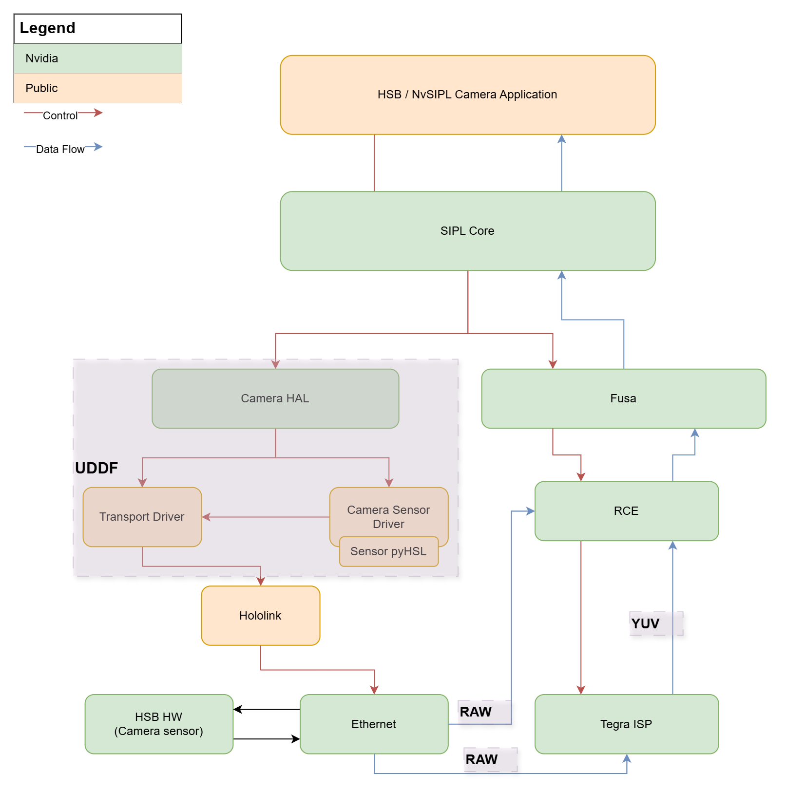
CoE architecture with MGBE/Ethernet-based control and data path in SIPL framework.#
The CoE architecture consists of the following major components:
SIPL Core and Pipeline
Provides APIs for SIPL applications to initialize camera pipelines.
Manages capture streams and buffers (both raw and ISP-processed outputs).
Reports events and errors via SIPL notifications.
Camera Drivers (via UDDF/HSL)
Implements camera bring-up and control within a standardized driver model.
Discovers and configures HSB and CoE camera devices on the network.
Camera Hardware Access (via Hololink drivers and Holoscan bridge library)
Provides I2C tunneling through HSB to configure sensors and related module components.
Ethernet Network/PHY (MGBE Controller)
Receives and classifies Ethernet packets containing camera data.
RCE Firmware
Manages DMA channels, handles interrupts, and processes frame events.
Simplified Flow Diagram#
+-----------------------------+
|         SIPL Core           |
+-----------+---------+-------+
            |         |
            |         |
            |         v
            |    +-----------------------------+
            |    | Transport Abstraction       |
            |    | (CoE, GMSL, etc.)           |
            |    +---------------+-------------+
            |                    |
            v                    v
+----------------+      +---------------------+          +-------------------+
| Image Proc.    |      | UDDF CoE Driver     | <------> | HSL (Hardware     |
| Pipeline       |      +----------+----------+          | Sequence Language)|
+-------+--------+                 |                     +-------------------+
                                   |
                                   |
                                   v
                        +----------------------------+
                        | Camera / Transport driver  |
                        | HW access (I2C tunneling)  |
                        | via Hololink driver        |
                        +----------------------------+
                                   |
                                   v
                        +----------------------------+
                        | Ethernet PHY/Network       |
                        +----------------------------+
                                   |
                                   v
                        +----------------------------+
                        | HSB (CoE camera)           |
                        +----------------------------+
Benefits and Limitations of CoE Compared to GMSL/MIPI CSI#
Feature |
CoE |
GMSL/MIPI CSI |
|---|---|---|
Cable Length |
More than 100 m (Ethernet) |
GMSL: ~15 m
MIPI CSI: less than 1 m
|
Topology |
Star, daisy-chain |
Point-to-point |
Networking |
Standard Ethernet |
Proprietary |
Hot-plug Support |
Yes |
Limited |
Scalability |
High |
Moderate |
Interoperability |
High |
Low |
Cost |
Lower (commodity) |
Higher (custom) |
Bandwidth |
More than 1 Gbps |
Up to 6 Gbps (GMSL) |
Limitations
Latency might be greater than direct MIPI CSI.
Requires Ethernet infrastructure and configuration.
Some advanced camera features might require custom driver support.
Supported Image Formats#
CoE supports a wide range of image pixel formats. The currently supported and validated formats are RAW10 and RAW12. The protocol allows for flexible payloads, but the following formats can be supported and consumed by the ISP:
Format |
Description |
|---|---|
RAW8 |
8 bits per pixel, sent as individual bytes. |
RAW10 |
10 bits per pixel, packed (3 pixels in 4 bytes). |
RAW12 |
12 bits per pixel, packed (2 pixels in 3 bytes). |
RAW14 |
14 bits per pixel, sent in 2 bytes. |
RAW16 |
16 bits per pixel, sent in 2 bytes. |
RAW20 |
Companded to fit in 2 bytes. |
RAW24 |
Sent in 3 bytes or companded. |
RAW28 |
Companded to fit in 2 bytes. |
RAW32 |
Sent in 4 bytes or companded. |
Software Flow: Steps in CoE Operation#
A typical CoE camera operation involves the following steps:
Platform, Driver, and Ethernet Initialization
Ethernet interface is brought up.
Clocks and links are configured by the platform.
MGBE is powered up.
Rx channels are initialized.
Application Startup (SIPL)
Load and parse configuration.
Initialize SIPL camera pipeline.
Allocate capture buffers and register them with RCE.
RCE Channel Setup
Initialize DMA channels, filtering and classification rules, and interrupts.
Network Configuration
Network interface is brought up.
If needed, MACSEC session is established.
Configure MGBE for frame reception.
Device Discovery and Configuration
Discover CoE camera/bridge (HSB) devices on the network.
Configure camera sensor/module over I2C (tunneled via the transport).
Capture and Processing
Receive pixel data over Ethernet.
Deliver frames to applications via SIPL APIs (both raw and ISP outputs are supported).
Status and Events Reporting
Capture and process completion status and events are reported to the SIPL applications, so that applications can receive and process the captured frame data.
Key Implementation Details
Hardware performs zero-copy DMA directly to application memory.
Interrupts efficiently detect SOF and EOF events to report capture completion status and events to the SIPL applications.
Pipelined operation allows submitting new requests while previous frames are being processed.
Buffer state tracking ensures proper synchronization between hardware and software.
CoE Data and Control Path Flow#
The control path in CoE manages camera configuration, I2C tunneling, and runtime control of camera modules over Ethernet. This path ensures that all configuration and control commands reach the camera sensor, EEPROM, and lens devices, if any, even when they are connected via an HSB.
Refer to the next section for UDDF and HSL in the CoE control path for sensor drivers.
The data path in CoE receives the raw image data from the camera sensor and delivers it to the SIPL applications, either after processing through ISP in YUV format or bypassing the ISP processing per the application’s request, along with the capture completion status and events, through RCE and FuSa Capture library.
UDDF and HSL in the CoE Control Path for Camera Drivers#
UDDF (Unified Device Driver Framework)
UDDF provides a modular, extensible driver model for camera devices in SIPL framework.
Defines the public driver interfaces used by camera and transport drivers.
Supports dynamic discovery and configuration of camera and transport devices.
In the CoE context, UDDF drivers abstract the details of Ethernet transport, bridge management, and sensor control.
UDDF drivers are configured via the JSON/CameraConfig mechanism, ensuring consistent initialization and runtime control.
The UDDF driver stack includes the following:
Transport Driver: Handles Ethernet communication and bridge discovery and configuration.
Sensor Driver: Implements sensor-specific logic, using the transport driver for I2C tunneling.
EEPROM/Lens Drivers: Support additional module components, all managed via the same UDDF abstraction.
HSL (Hardware Sequence Language)
HSL is used to describe and execute complex hardware access sequences (such as I2C and GPIO access and sensor programming).
In the CoE control path, HSL scripts can be invoked by the UDDF driver to do the following:
Initialize the sensor and bridge in the correct order.
Perform timing-sensitive operations (such as reset, power-on, and synchronization).
Support advanced features like trigger mode or multi-sensor sync.
HSL scripts are referenced in the JSON configuration and executed by the driver stack as needed.
For more details on HSL and UDDF, refer to HSL and UDDF Overview.
Camera and Transport Configuration#
Camera sensors and transport devices are configured to be controlled through I2C bus transactions from the Jetson platform via I2C tunneling going through the HSB bridge and Ethernet network.
Here is how it works for HSB as compared to MIPI CSI and GMSL:
For HSB cameras, I2Cs are tunneled through the Ethernet network (potentially a series of Ethernet switches) transparently to the host camera driver software.
For native CSI cameras, the I2C interface connects directly to the host SoC, and the host software directly controls the I2C devices.
With GMSL cameras, I2Cs are tunneled through the deserializer/serializer transparently to the host camera driver software.
As mentioned earlier, JSON files configure the camera and transport devices.
Example JSON fragment for HSB transport configuration:
"transportSettings": [
   {
      "name": "HsbTransport",
      "type": "CoE",
      "description": "Transport settings for VB1940 camera",
      "if_name": "eth0",
      "ip_address": "192.168.1.2",
      "vlan_enable": false,
      "hsb_id": 0
   }
]
For more details about writing JSON configuration files, refer to SIPL Query JSON Guide for CoE Camera Development.