NVLink Switch Planning, Design, and Deployment Guide using Base Command Manager (BCM)#
This section provides an overview of the planning, design, and deployment process for NVLink Switch using the BCM.
NVLink Switch Planning#
When planning the NVLink Switch, you need to consider the following:
Hardware Components and Models#
Confirm the you have the accurate hardware models and correct amount. You can reference this list of items:
Kubernetes Admin|User nodes Server - 3x
NVLink Switches (non-scaleout) - 9x per rack
Optical Transceivers and DAC/AOC cables
Fiber and Copper cables
Network and Connectivity Requirements#
The following are the key network and connectivity requirements to consider when planning your NVLink Switch deployment:
Kubernetes Admin|User nodes to BTOR switch connectivity
Transceiver type, compatibility and HW order status
Electrical signaling/encoding (NRZ vs PAM4)
Speed/Bandwidth
IP Addressing
Logical Connectivity (Access and Bonded)
NVLink Switch to OOB Switch connectivity
Copper connections
Speed/Bandwidth
IP Addressing
Logical Connectivity (Access)
Routable IP Address Allocation
Kubernetes Admin|User nodes server will have IP addresses allocated from Inband and OOB (ComE0) subnets.
NVLink Switches will have IP addresses allocated from OOB (ComE0) subnets.
Kubernetes Admin|User nodes and NVLink Switch Connectivity - To provision and manage NVLink Switch/NVLink.
Use the default partition.
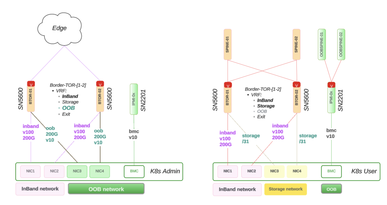
Figure 11 NVLink Switch Network Allocation Diagram#
NVLink Switch Design#
This section provides details on the NVLink Switch design, including:
Physical connectivity
Network allocation diagram
NVLink Switch integration with BCM verification
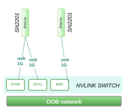
The following diagram shows how the NVLink Switch connects to the Rack Switch using the NIC-COM ports and BMC on the OOB network.
Physical Connectivity#
The following are the reference design for the NVLink Switch connectivity:
ComE1: 1G connects to within Rack Switch: SN2201 on RU 45
ComE2: 1G connects to within Rack Switch: SN2201 on RU 45
BMC: 1G connects to within Rack Switch: SN2201 on RU 44
Network Allocation Diagram#
This following network workflow diagram shows how the above ComE1, ComE2, and BMC are a part of the larger OOB subnet that covers 4 x GB200 racks:
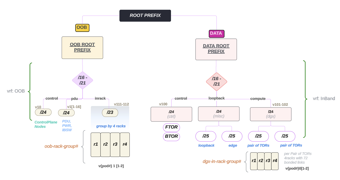
Figure 12 NVLink Switch Network Allocation Diagram#
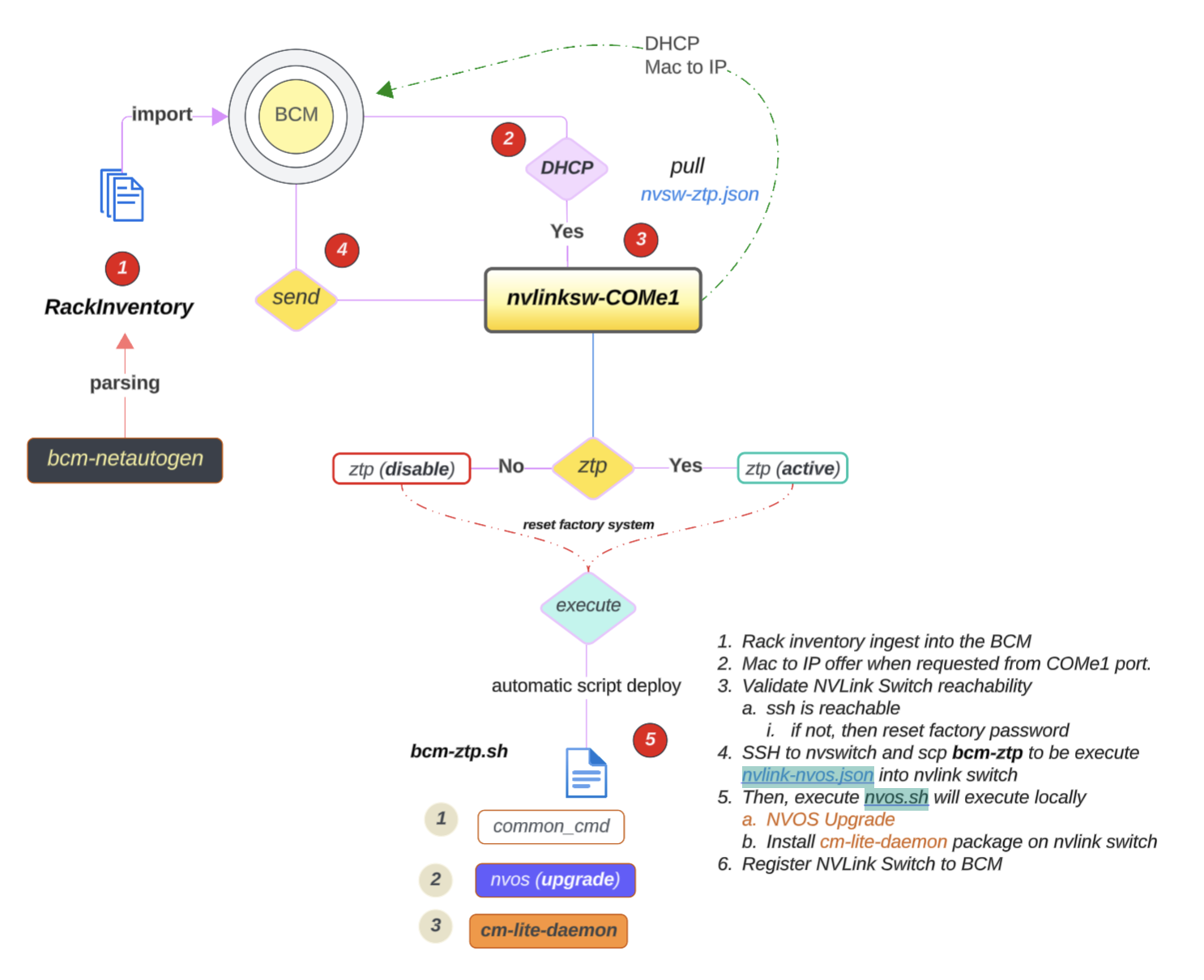
NVLink Switch Integration with BCM Verification#
The following image shows the workflow diagram of NVLink Switch integration with BCM:
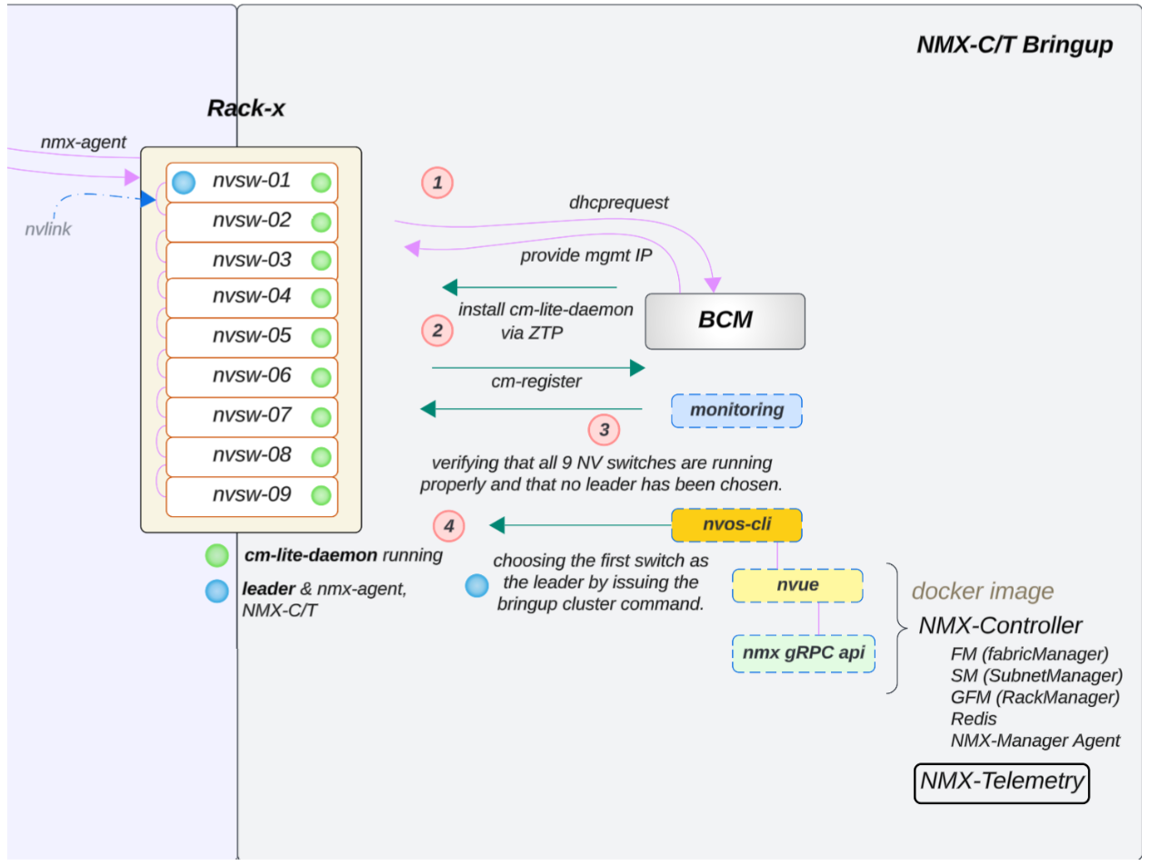
Figure 13 NVLink Switch Integration Workflow#
Verify the NVLink Switch Configuration#
To verify that the NVLink Switch configuration is correct:
Confirm OOB power control of the NVLink Switches using a power status check in BCM, similar to what was done for a GB200 compute tray.
Verify that an NVLink Switch can be reached through SSH from the head node using the admin user. The password may have been initially set during the bcm-netautogen (also known as netautogen) process. A typical password is admin.
ssh admin@<RACK_LOCATION>-NVSW-01Set the password to match what has been put into BCM for the NVLink Switch entry under accesssettings.
Verify that the following NVLink Switch parameters are set correctly:
NV configuration mode
NV configuration file
FM config file

Figure 14 NVLink Switch Parameter Settings#
Run the following command to verify the NVLink Switch parameters:
$ cmsh > device > use <NVLINK_SWITCH_NAME> ztpsettings
Updating the NVLink Switch to the Latest Firmware#
If the NVLink Switch is running a version earlier than v25.02.2134, the custom script and the cm-lite-daemon will not be installed.
However, once the NVLink Switch is upgraded to a newer version using ZTP, it will recognize the custom script option and install the cm-lite-daemon.
This process will take approximately 2-4 minutes longer than a standard ZTP.
The following flow diagram shows how the NVLink Switch is updated to the latest firmware:
To update the NVLink Switch to the latest version, you can use the following steps:#
If the NVLink Switch comes pre-installed with NVOS from the factory and the factory password has already been reset, NVOS Zero Touch Provisioning (ZTP) will be disabled.
The NVOS-ZTP script will be executed once the device is reachable.
Reset the NVLink Switch System to a factory reset.
Run the following command to reset the NVLink Switch System to a factory reset:
$ nv action reset system factory-default force
The NVLink Switch will reboot automatically (takes ~2.3mins)
Wait for the NVLink Switch to come back online.
On the backend, the following things will happen:
It will pull the nvlink-nvos.json file, validate the format, and create folders per section in
/var/lib/ztp/sections.It then executes each section one by one. For each section, it does the following:
Verifies network connectivity
Upgrades the NVOS image
Adjusts the security settings and disables password hardening
Applies the generated startup.yaml and patch configuration
Executes the nvos-ztp.sh script to install cm-lite-daemon, which does the following:
After the NVLink Switches are up and running within the rack, the system will automatically perform a Leader selection process
Out of 9, select 1 NVLink Switch:
Apply fm_config
Enable the cluster
Once the cluster is enabled, the NVLink Switch will be ready to use.