BCM Software Installation#
Installing the BCM software on the designated server head node can be summarized as:
Download the installer ISO.
Transfer the installer ISO to a newly formatted USB drive media for physical installation. This is often required if the cluster network has not yet been configured, and the deployment engineer uses BCM network automation (bcm-netautogen) to create the switch configuration.
For remote installations, the ISO can be mounted in the remote server’s KVM interface through the IPMI/BMC.
Run the installer.
Install the license.
After this, the configuration of BCM to provision the control plane nodes and the GB200 racks is finished. The next step below mirrors the process documented in the BCM 11 Installation Manual but includes specific choices for a reference DGX SuperPOD design.
Acquire BCM ISO#
The following steps show how to acquire the BCM ISO:
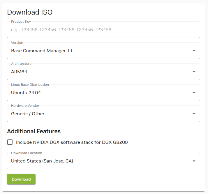
For downloading production versions of BCM, go to https://customer.brightcomputing.com/download-iso.
Select the version of BCM.
Enter the customer’s product key.
Select the architecture of the server that it is being installed on
(x86_64oraarch64/arm64).Note
In all GB200/GB300 deployments, a mixed architecture BCM 11 setup is required. To ease the installation process, be sure to download both ISOs.
Select
Ubuntu 24.04as the base distribution.Select
NVIDIA DGXas the Hardware Vendor.If aarch64/arm64 is selected, check the box for Include NVIDIA DGX software stack for DGX GB200. If x86 is selected, do not select Include the NVIDIA DGX software stack for Include NVIDIA DGX software stack for DGX B200/H100/H200.
Select the closest download location.
Note
An NVIDIA Mission Control or DGX-enabled license is required in order to download a BCM ISO that includes the DGX OS stack. Without this entitlement, DGX OS components will not be available within the ISO download options.
Verify the downloaded ISO with an MD5 checksum.
The .md5 file is available with the ISO download. Run an MD5 checksum to make sure the .ISO files are not somehow corrupted.
In Windows Powershell, run it as an Admin, then use the following command:
Get-FileHash bcm-11.0-ubuntu2404-dgx.iso -Algorithm MD5

Algorithm Hash Path
--------- ---- ----
MD5       5C4CBA5B594B4E7491F4A15E35A36DB4
If a terminal in Linux or MacOS is used, use this command:
md5sum bcm-11.0-ubuntu2404-dgx.isoIf the MD5 checksum matches, then the ISO is valid and can be used for installation.
5c4cba5b594b4e7491f4a15e35a36db4 bcm-11.0-ubuntu2404-dgx.iso
BCM Software Installation#
BCM 11 can be installed from various sources of media, depending on whether the deployment engineer is local or remote. For more in-depth details on BCM 11 installation, consult the BCM 11 Installation Manual.
Caution
Identify the correct headnode server(s) details before beginning this step. Furthermore, confirm that the hardware available in the designated rack location has the correct BOM/configuration. Ensure that it has enough network connections/NICs.
Method 1—Remote Installation#
Remote BMC/IPMI access has been established over the customer network.
Obtain BMC/IPMI access credentials for the node. For some OEMs, credentials are listed on the system asset tag. In other cases, a generic user/password combination is used, which may need to be reset before installation.
A BCM 11 .iso has been obtained and mounted on the head node server’s virtual media interface through its KVM.
Boot the node into the mounted .iso and begin the installation.
Method 2—Local Installation#
Create a bootable USB: Use an ISO burning tool to burn the image to a USB device, the following have been verified as functional options:
Any software that can use the Linux/UNIX dd command and image to a USB will work.
Obtain a crash cart or a local KVM device and plug the video interface, mouse, and keyboard into the server.
Plug the bootable install USB you created earlier into an available USB port on the server.
Boot into the server’s SBIOS menu and in the BOOT menu select the above USB drive to boot from.
Note
The remote KVM method can also be used with a USB drive locally inserted. Enter the SBIOS menu through the KVM and select the bootable USB drive.
Server Boot Settings#
Head node(s): set to boot from hard drive.
For the secondary head node, initially set it to PXE boot. After BCM HA configuration, set it to boot from the hard drive.
Note
Ensure that the BIOS of the target head node is configured in UEFI mode and that its boot order is configured to boot the media containing the BCM installer image.
Control nodes: set to PXE boot using IPv4.
GB200 nodes: by default, the Bluefield-3 cards should be set to PXE boot. If they are not, or the BF3 cards do not appear available, see Appendix for troubleshooting and additional information.
Install the Software#
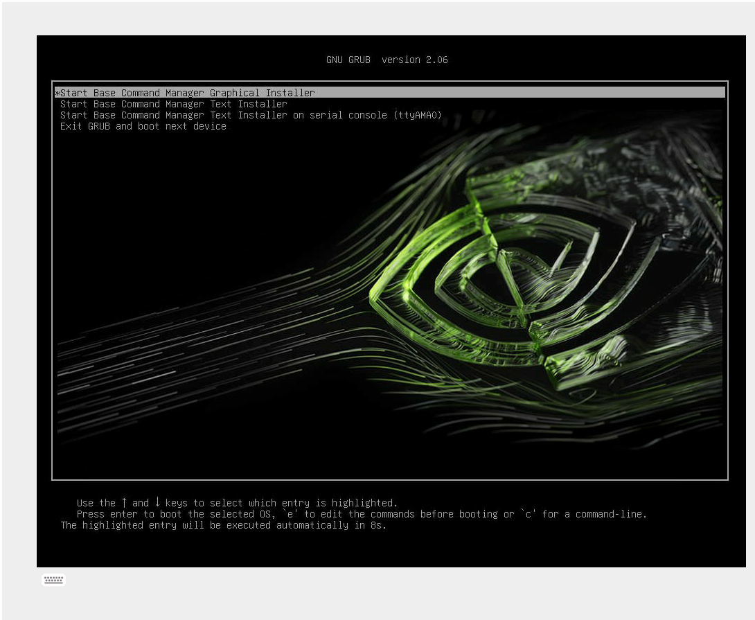
Boot from the installation media.
From the Grub menu, choose Start Base Command Manager Graphical Installer.
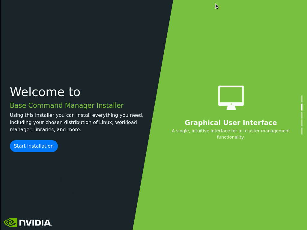
Select Start installation on the splash screen.
Note
At any time during the installation, use Ctrl+Alt+F2 to get to a shell, then Ctrl+Alt+F1 to get back to the GUI.
Accept the terms and conditions of the NVIDIA EULA by clicking the I agree checkbox and then select Next.
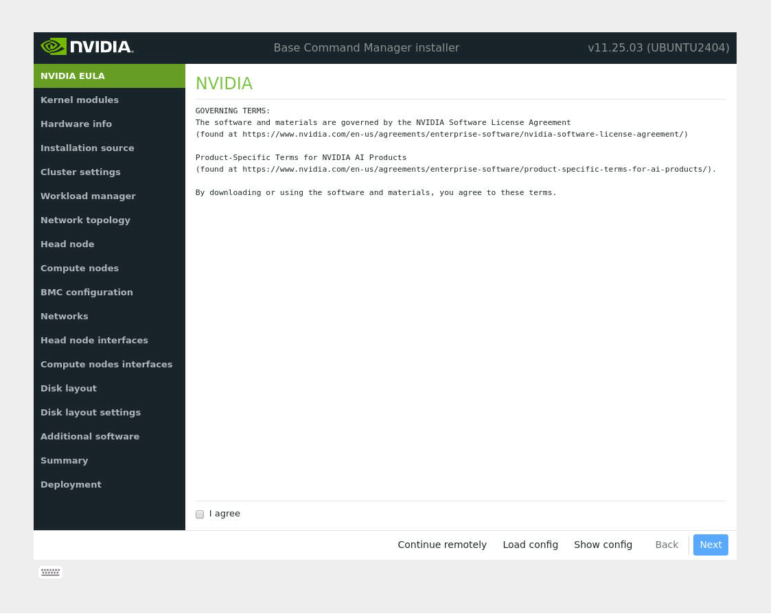
Accept the terms of the Ubuntu Server EULA by checking I agree checkbox and then select Next to continue.
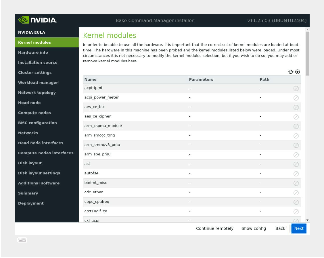
Unless instructed otherwise, select Next without modifying the kernel modules to be loaded.
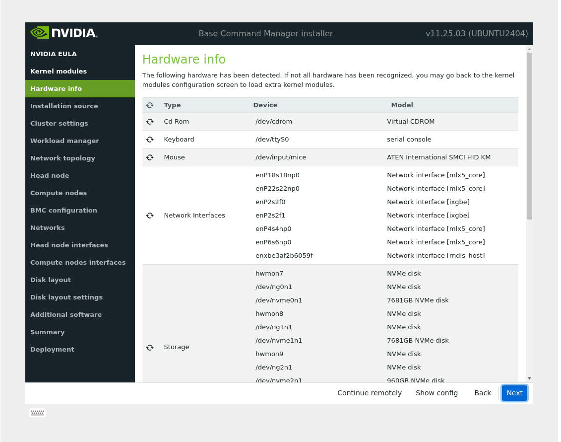
Verify that the Hardware info is correct and then select Next.
Do the available disks for installation and partitioning look consistent with the known hardware in the system?
For the netnames identified by the installer, look at the total connections and surmise which ports are LAN on Motherboard (LOM) or add-in PCIe cards.
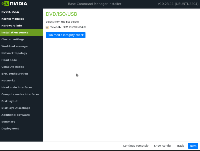
On the Installation source screen, choose the source and then select Next. Running a media integrity check is optional.
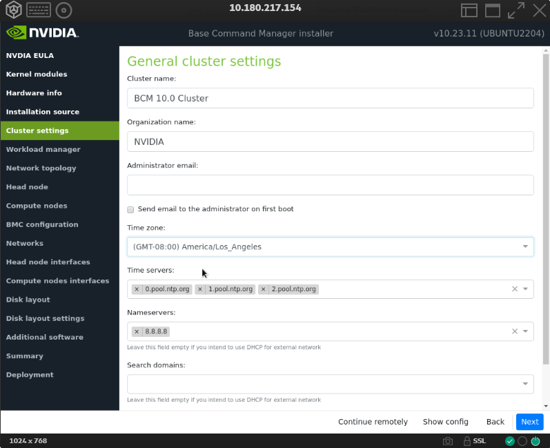
On the Cluster settings screen, enter the required information and then select Next. Having the correct time servers and nameservers is important. However, these can be changed in the CMDaemon shell (cmsh) later.
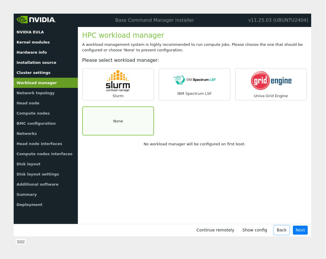
On the Workload manager screen, choose None and then select Next.
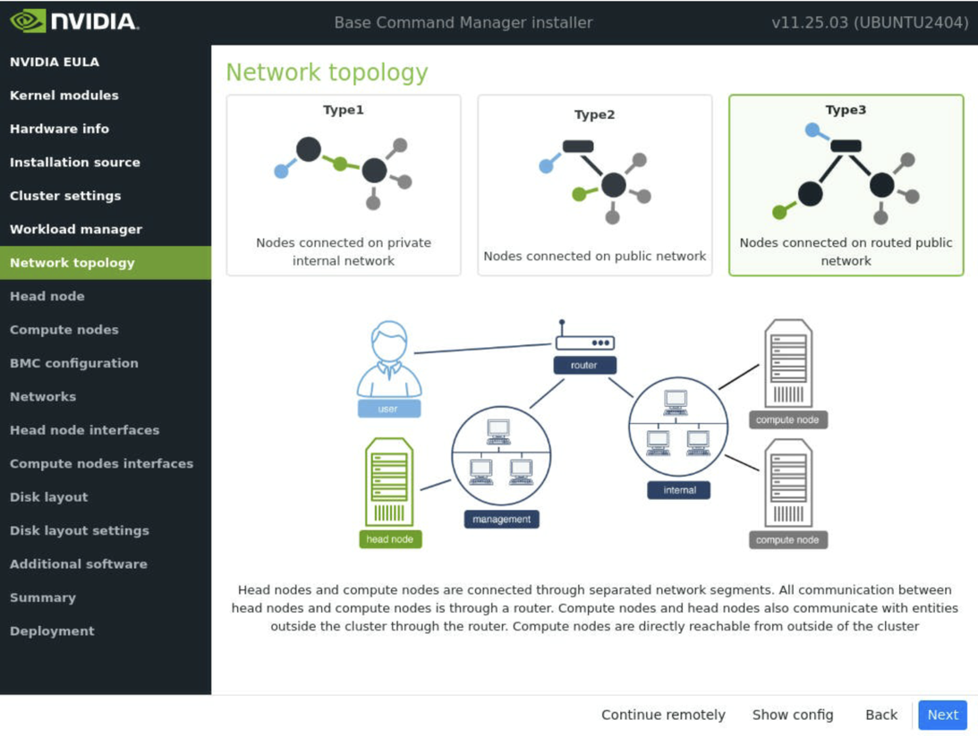
On the Network topology screen, choose the network type for the data center environment and then select Next.
Note
For a DGX SuperPOD, select Type 3 network. For a description of the other network types and which one should be chosen based on the deployment, please refer to section 3.3.13 of the BCM 11 Installation Manual
If the Type 1 or Type 2 network is selected, the next screen will not have the option to configure managementnet.
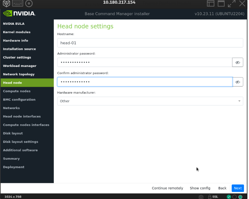
On the Head node settings screen, enter the Hostname, Administrator password, choose Other for Hardware manufacturer, and then select Next.
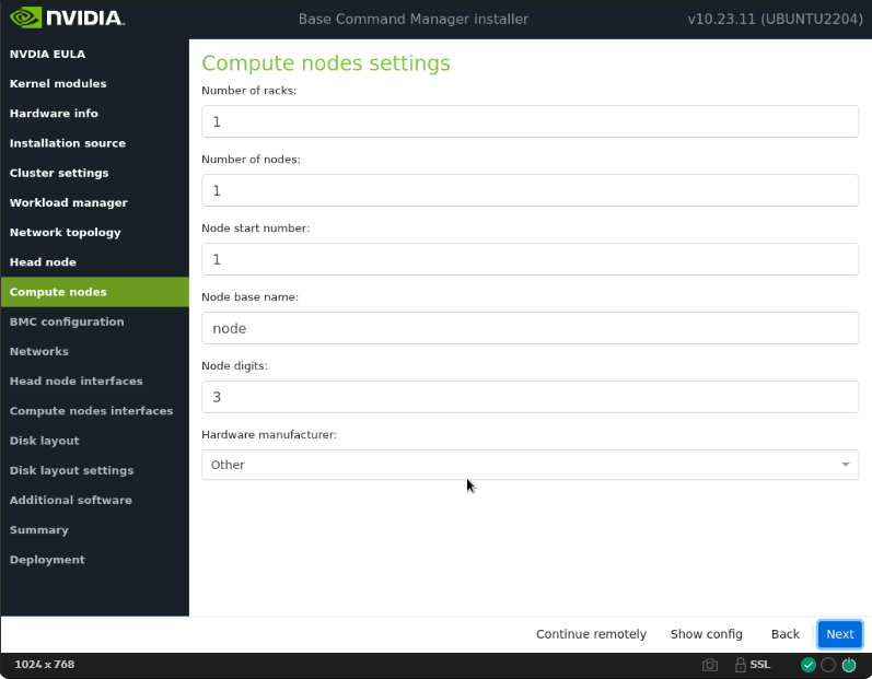
Accept defaults in the Compute nodes and then select Next.
On the BMC configuration screen, choose No for both the Head Node and Compute Nodes, and then select Next.
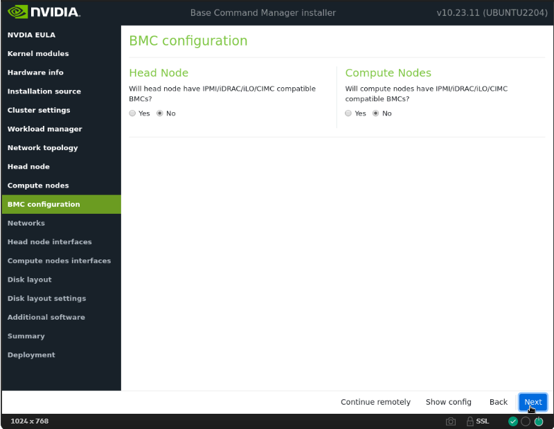
Note
These will be updated later in the post-install stages.
On the Networks screen, enter the required information for internalnet, and then select Next.
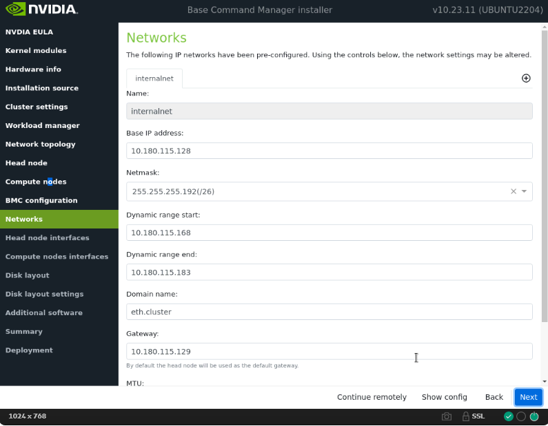
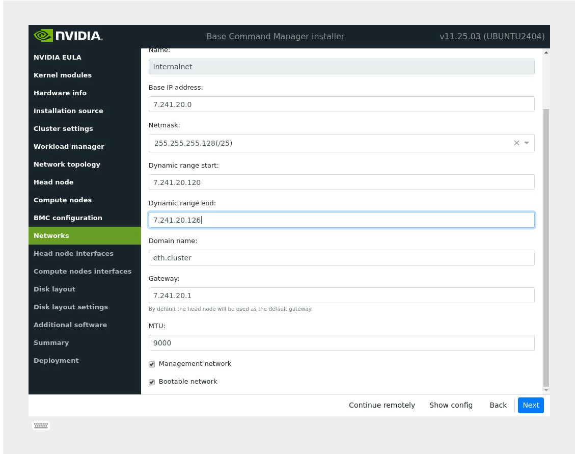
When Type 3 is chosen, two network values (
internalnetandmanagementnet) need to be defined. For managementnet, use a DGX subnet for now. The true value will be corrected post-install.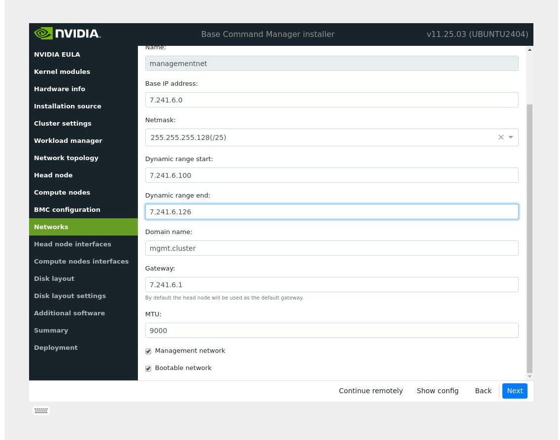
Note
If the Back button is used to return to this screen after pressing Next, the dynamic range values will be reset.
Because No was selected for BMC configuration, the default entry for ipminet will not appear.
When a Type 1 network is selected, tabs for externalnet will be present. For traffic from the cluster private network (internalnet) to correctly route through the headnode to externalnet, ensure that the internalnet gateway is set to
0.0.0.0. Externalnet requires an IP and gateway.When a Type 2 network is selected, there are no other network tabs (ex. externalnet or ipminet). In a KVM setup, this is typically the network type that should be selected.
When a Type 3 network (DGX SuperPOD default) is selected, internalnet and managementnet will be the default networks that need to be configured. In this context, managementnet is the same as the subnet that services the DGX GB200 compute nodes (dgxnet).
For more information, see section 3.3.13 of the BCM 11 Installation Manual.
On the Head node network interfaces screen, ensure that one interface is configured with the head node’s target internalnet IP, and then select Next.
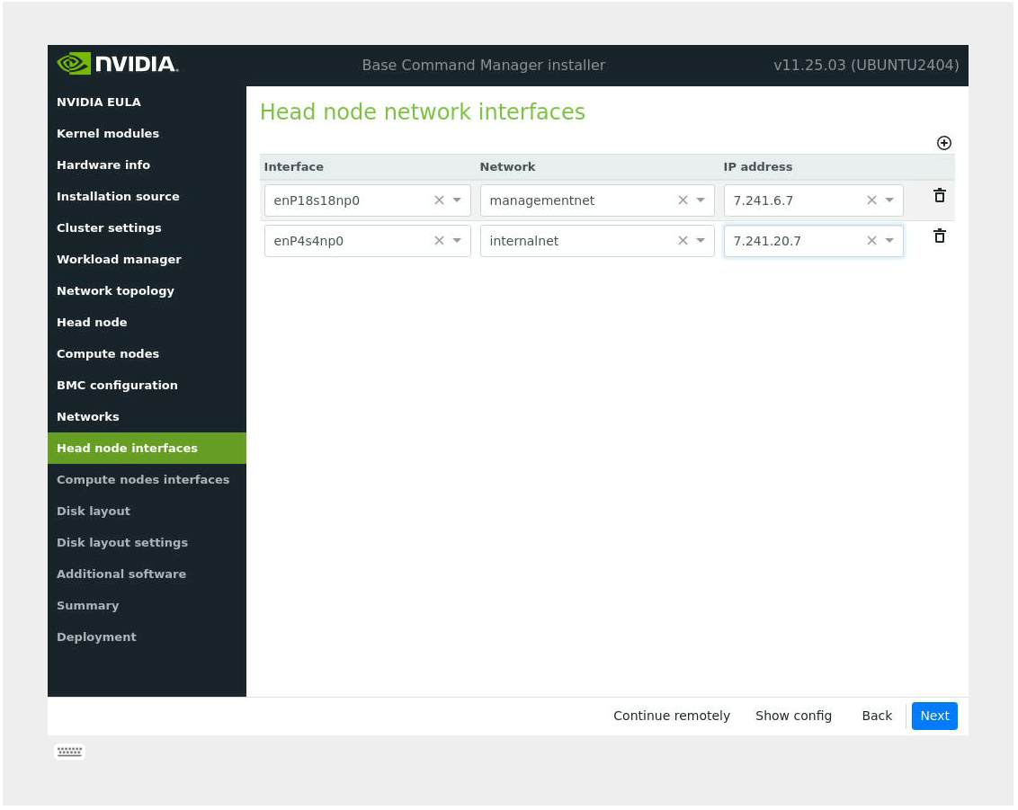
Note
Ensure that the correct interface is chosen for the headnode’s connection to internalnet and confirm that its link is up. cmsh will default to this address and interface and if it is not up, cmsh will say that the cluster is unreachable. After installation, if this is the case, the administrator can always enter cmsh through the loopback interface which is typically
127.0.0.1. This can be confirmed by doingip a.Other interfaces will be configured manually by a deployment engineer for the network bonds needed for internalnet communications and other networks such as ipminet.
For the Type 3 networking setup, use an IP that is in the range of the managementnet network defined in the previous step to progress. Assign it to an interface that will not be part of the internalnet bond that is created later in the installation process. This will be changed after the installation wizard is completed.
On the Compute node interfaces screen, leave the default entries, and then select Next.
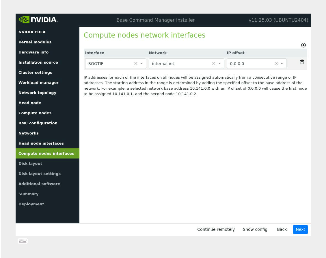
These will be updated post install.
- On the Disk layout screen, select the target install location and then select Next.
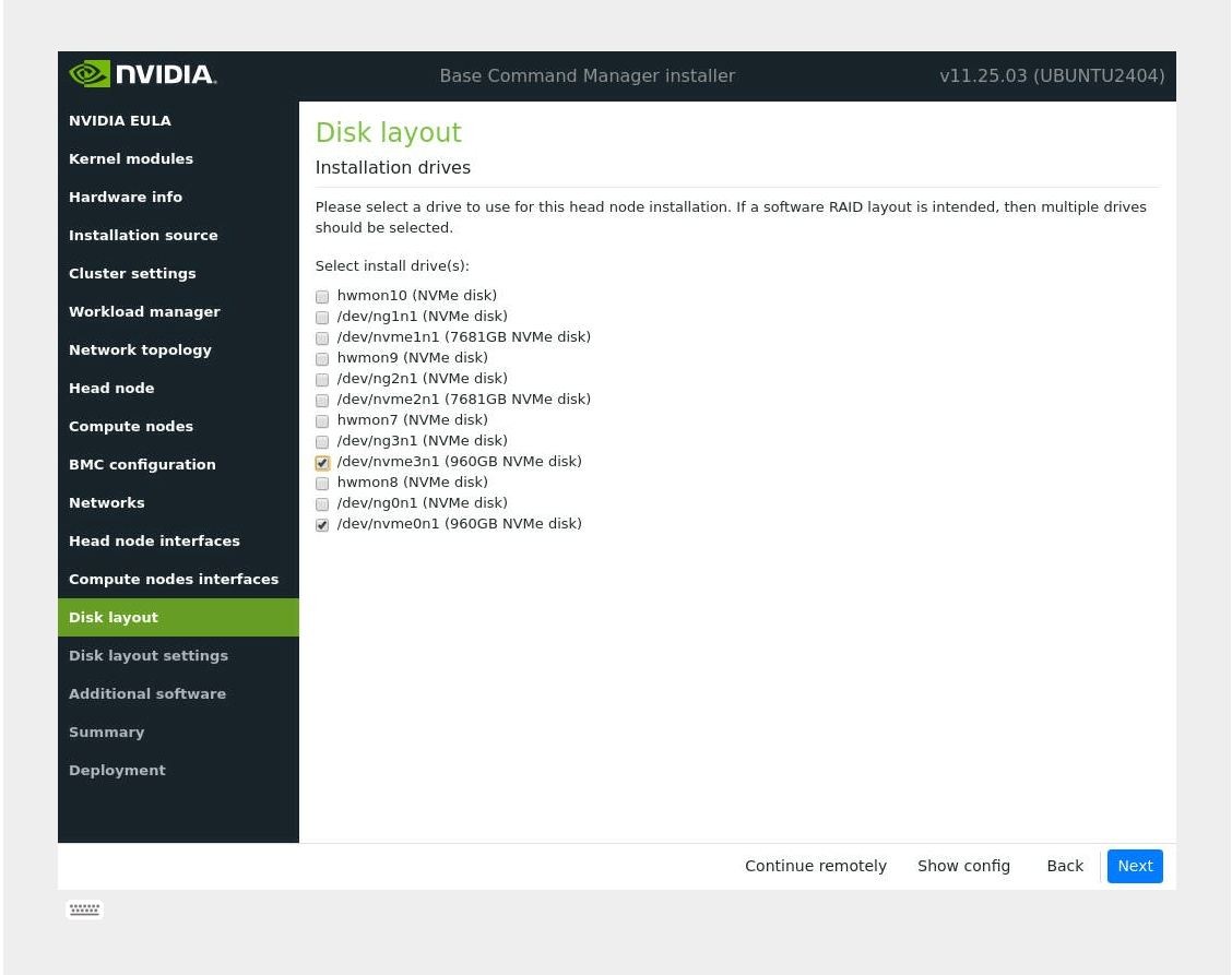
Note
For the head node disk layout, a RAID1 configuration is ideal. To identify two M.2 drives for software RAID configuration, they are normally the same model and size and are much smaller than the U.2 storage drives.
For Dell head nodes, if a Dell BOSS hardware RAID card is present, select that option and configure the M.2 drives in a RAID 1 configuration within the Dell iDRAC webUI.
Any other drive that is available, such as an array of U.2s, can be configured for usage after the installation. However, the administrator can create/edit a disksetup file if the drive layout is already known, and the administrator knows how it should be partitioned/configured.
On the Disk layout settings screen, accept defaults for the head node and then select Next unless the disk setup needs to be modified. If any particular changes need to be made, for example increasing the size of /var or setting up the disks to use LVM, this can be done here. For more information, see section 3.3.11 of the BCM 11 Installation Manual.
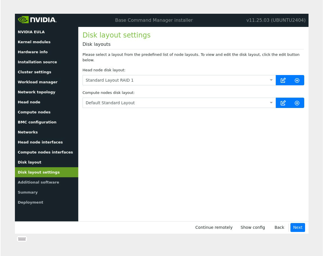
Note
For the head node, the disk layout cannot be reconfigured without formatting the hard drive and redoing the installation. For the compute nodes, these settings will be updated later in the post installation steps. For KVM setups, select One big partition BIOS GPT.
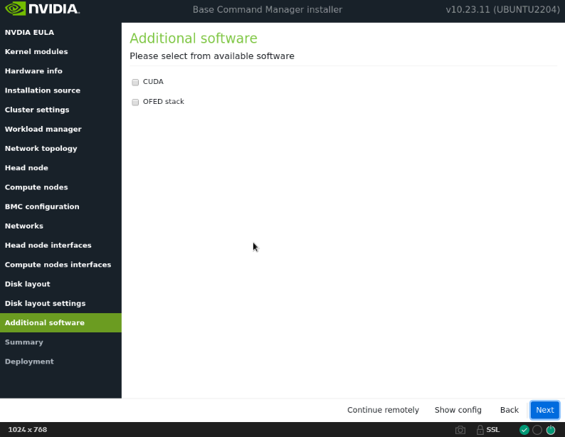
In the Additional software screen, do not choose anything and then select Next.
Confirm the information on the Summary screen and then select Start.
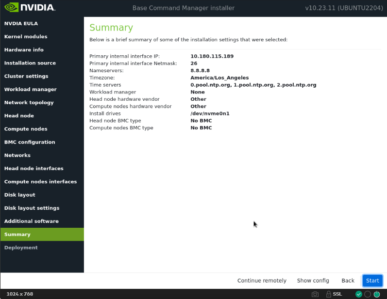
The summary screen provides an opportunity to confirm the head node and basic cluster configuration before deployment begins. This configuration will be updated/modified after deployment is complete. If any values do not match expectations, use the Back button to navigate to the appropriate screen to correct any mistakes.
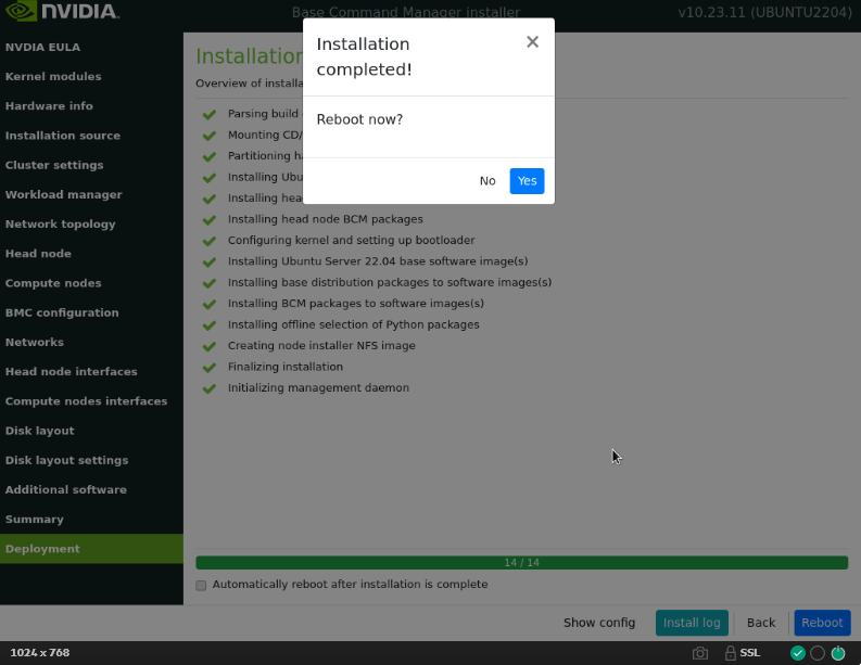
Once the deployment is complete, press the Reboot button and wait for the head node to reboot.
After reboot, confirm that head node is reachable using SSH.
If there is SSH access to the BCM head-node, proceed to license the cluster by running the request-license command and providing the product key.
Note
License needs to be enabled with NVIDIA Mission Control.
To license the cluster, run the following command:
$ sudo -i request-license
You will be prompted to enter the Product Key (format:
XXXXXX-XXXXXX-XXXXXX-XXXXXX-XXXXXX).Note
To set up HA, two MACs need to be put into the license. If there is access to both head nodes, it is preferable to choose a MAC that belongs to a LOM port on any NIC that cannot be removed from the system. Otherwise, if a non-embedded card is selected then fails and is removed, the license will fail because it cannot detect the defined MAC. BMC MAC addresses do not work for this purpose.