High Availability#
If the compute nodes have already been provisioned, they must be powered off before configuring HA.
To power off:
Verify that the head node has power control over the compute nodes.
At the node level:
cmsh;device;power status -n <NODE_NAME>.At the category level:
cmsh; device; power status -c dgx-gb200.At the rack level:
cmsh; device; power status -r <NODE_NAME>.
Example: Rack level power control confirmation
root@a03-p1-head-01:~# cmsh -c "device; power status -r b05 -i -c dgx-gb200" | sort

rf0 ...................... [ OFF ] b05-p1-dgx-05-c08
rf0 ...................... [ ON ] b05-p1-dgx-05-c01
rf0 ...................... [ ON ] b05-p1-dgx-05-c02
rf0 ...................... [ ON ] b05-p1-dgx-05-c03
rf0 ...................... [ ON ] b05-p1-dgx-05-c04
rf0 ...................... [ ON ] b05-p1-dgx-05-c05
rf0 ...................... [ ON ] b05-p1-dgx-05-c06
rf0 ...................... [ ON ] b05-p1-dgx-05-c07
rf0 ...................... [ ON ] b05-p1-dgx-05-c09
rf0 ...................... [ ON ] b05-p1-dgx-05-c10
rf0 ...................... [ ON ] b05-p1-dgx-05-c11
rf0 ...................... [ ON ] b05-p1-dgx-05-c12
rf0 ...................... [ ON ] b05-p1-dgx-05-c13
rf0 ...................... [ ON ] b05-p1-dgx-05-c14
rf0 ...................... [ ON ] b05-p1-dgx-05-c15
rf0 ...................... [ ON ] b05-p1-dgx-05-c16
rf0 ...................... [ ON ] b05-p1-dgx-05-c17
rf0 ...................... [ ON ] b05-p1-dgx-05-c18
If it responds with:
[ skipped] - the ipmi/bmc/rf0 interface is not defined for the node.
[ failed ] - likely the bmc user id, username, or user password is incorrect or have not been defined for the node entry.
Power off the cluster nodes.
CMHA Setup#
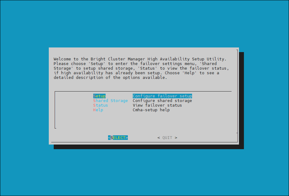
Start the cmha-setup CLI wizard as the root user on the primary head node.
cmha-setupChoose Setup and then select SELECT.
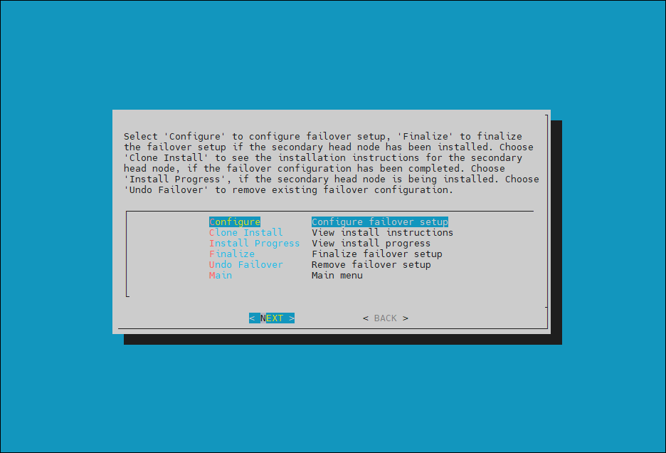
Choose Configure and then select NEXT.
Verify that the cluster license information found cmha-setup is correct and then select CONTINUE.
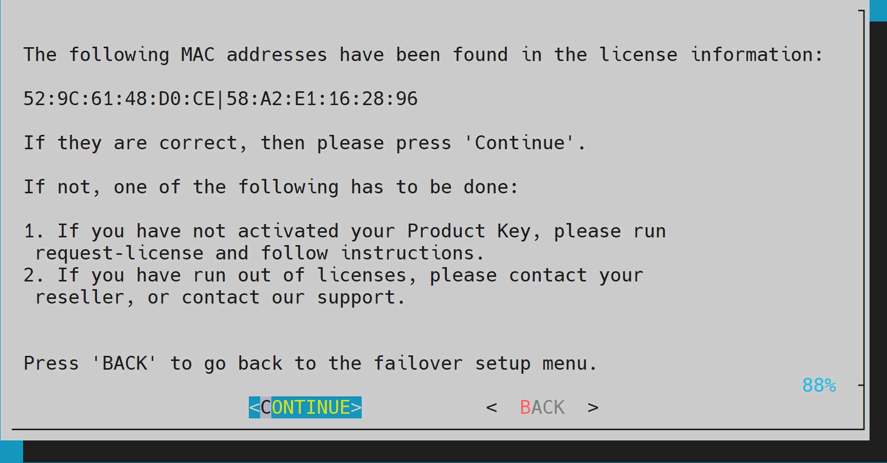
One MAC from each of the head nodes is required for the license. It is recommended that the MAC of an LOM port or any MAC of a device that cannot be removed from the system be used.
Provide an internal Virtual IP (VIP) address that is to be used by the active head node in the HA configuration. This should be in the bond0 subnet on internalnet.
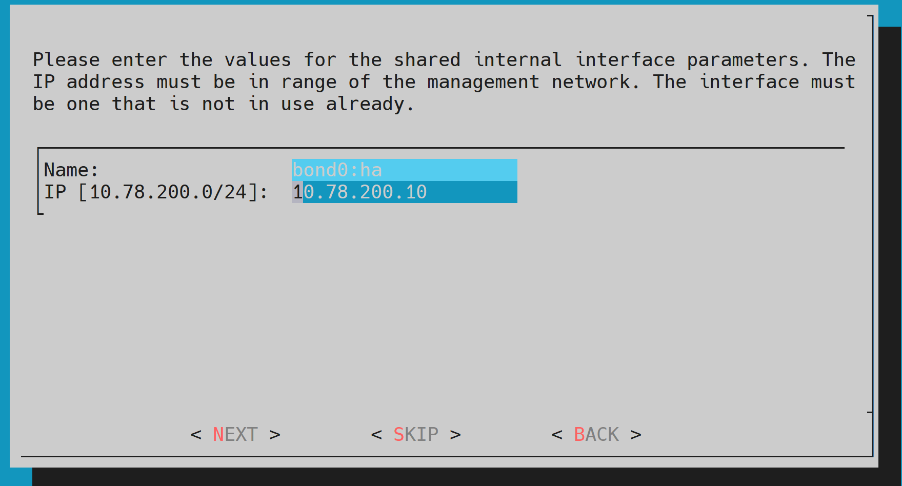
The bond0 alias for HA will appear as bond0:ha.
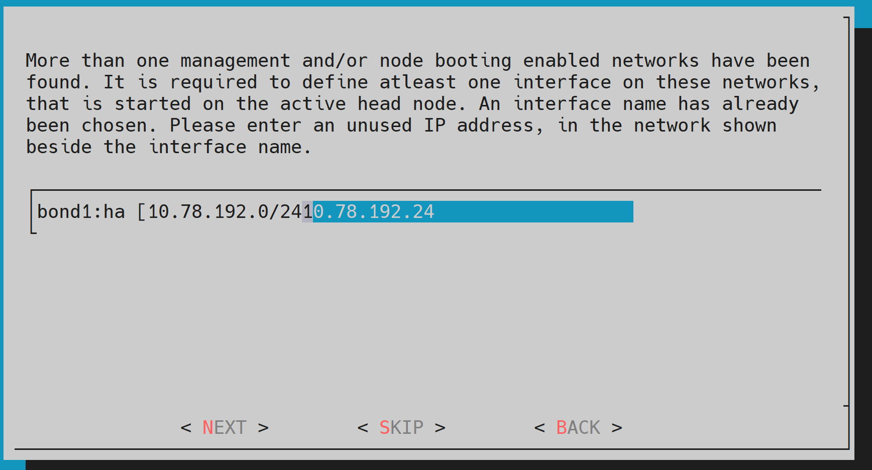
Provide another VIP address for the bond1 connection to the ipminet0 subnet. This is required so that the headnode can connect to the NVLink switches. Ensure the fourth octet match that of the bond0 VIP.
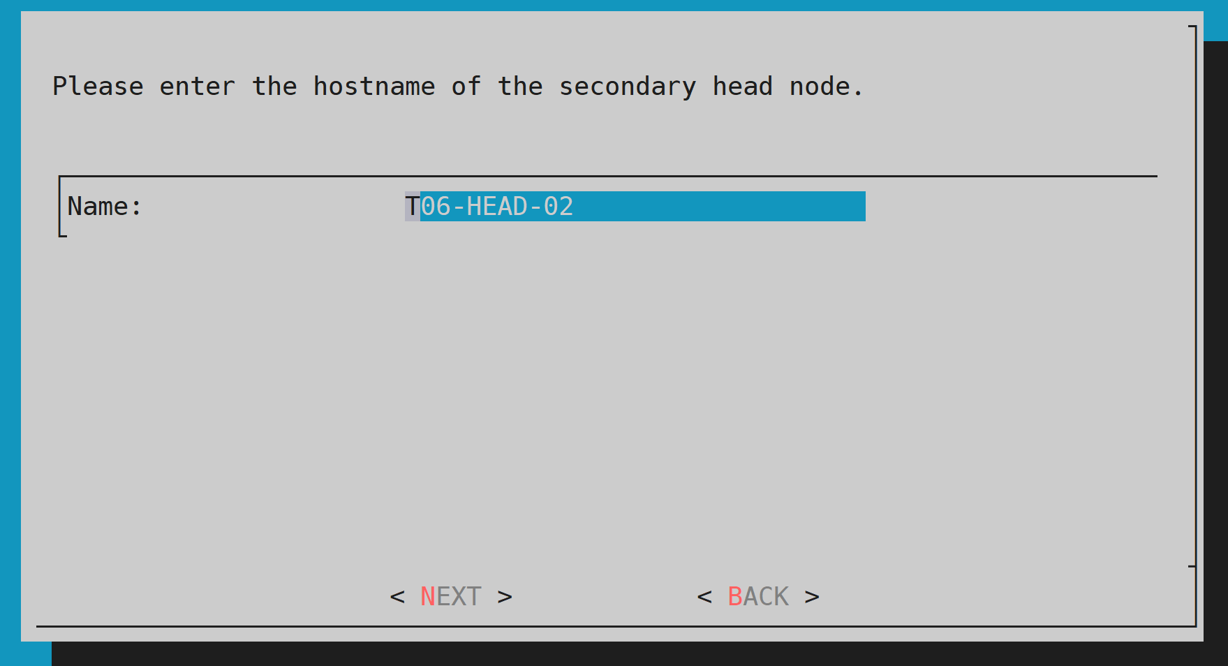
Provide the name of the secondary head node and then select NEXT.
Because DGX SuperPOD uses the internal network as the failover network, select SKIP.
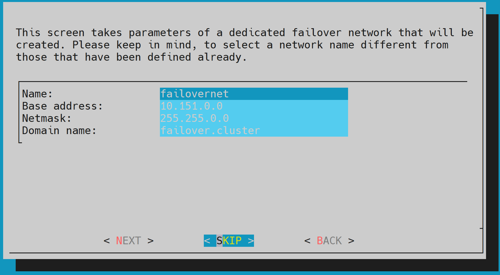
If a dedicated cable is used for failover, define the failover net. This can be a simple network as it is between two ports being used between the two head nodes.
Configure the IP addresses for the secondary head node that the wizard is about to create, and then select NEXT.
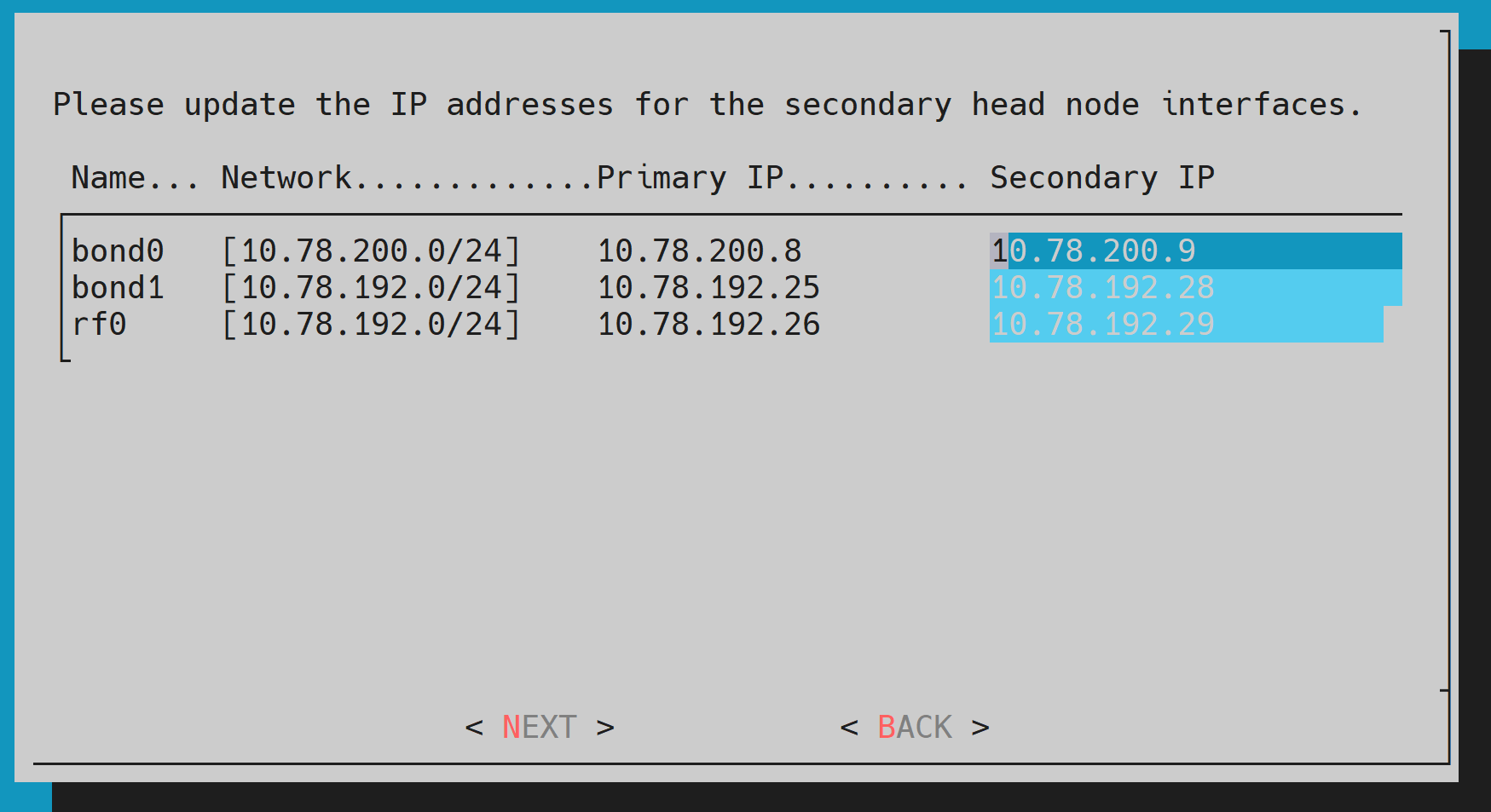
For an HA configuration, it is assumed the head nodes are of an identical configuration.
Select EXIT on the summary window.
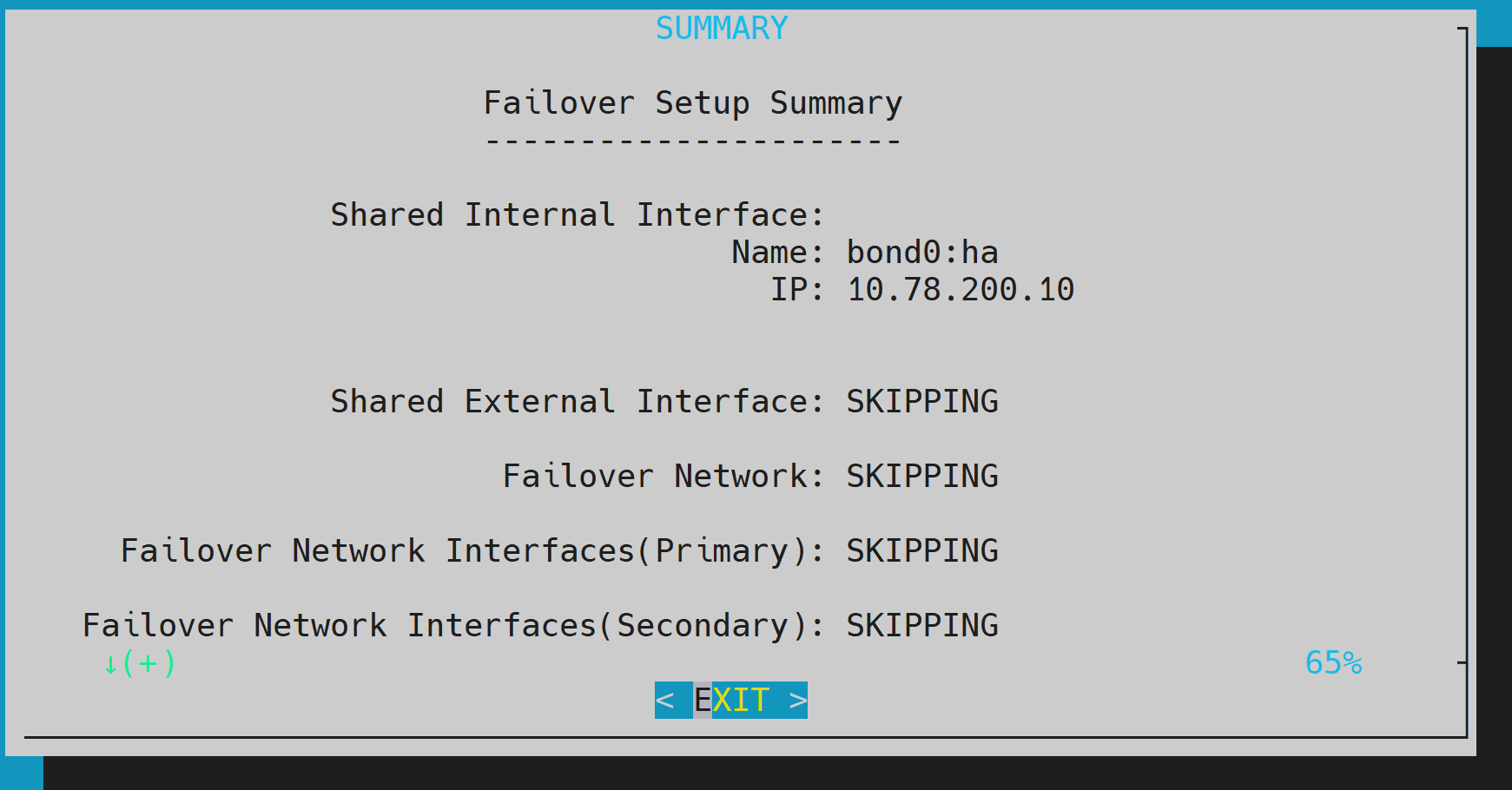
The wizard shows a summary of the information that it has collected. The VIP will be assigned to the internal and external interfaces, respectively.
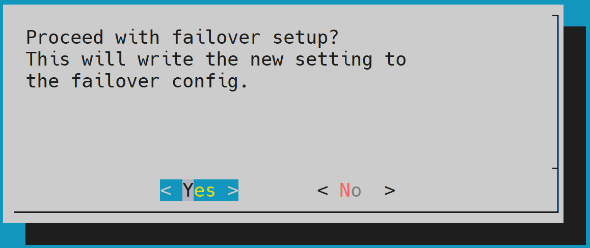
Select Yes to proceed with the failover configuration.
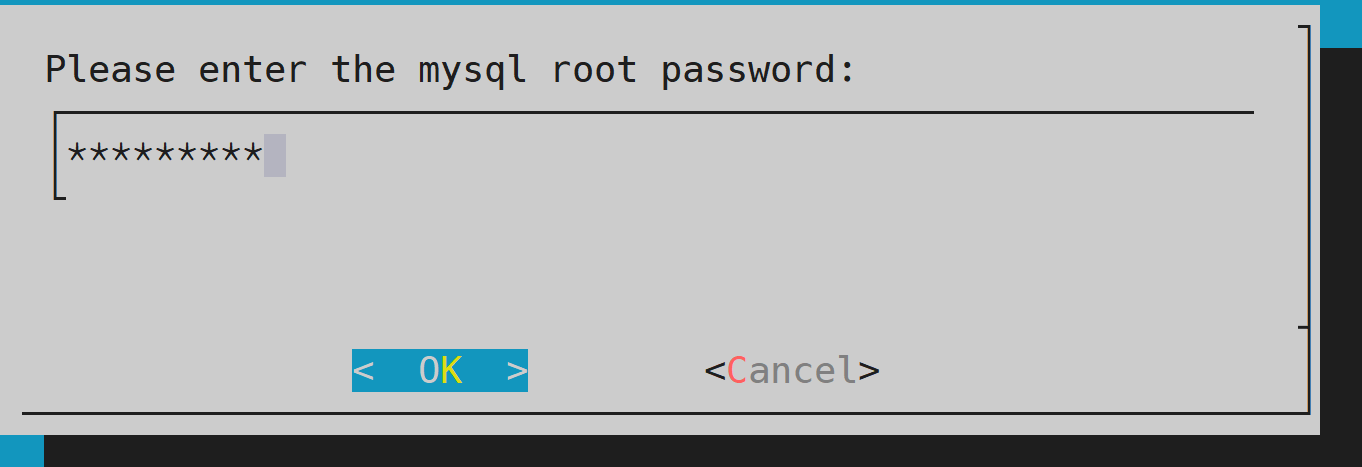
Enter the root password and then select OK.
The wizard implements the first steps in the HA configuration. If all the steps show OK, press ENTER to continue. Progress is shown in the following console output:
Initializing failover setup on master.............. [ OK ]
Updating shared internal interface................. [ OK ]
Updating shared external interface................. [ OK ]
Updating extra shared internal interfaces.......... [ OK ]
Cloning head node.................................. [ OK ]
Updating secondary master interfaces............... [ OK ]
Updating Failover Object........................... [ OK ]
Restarting cmdaemon................................ [ OK ]
Press any key to continue.
When the failover setup installation on the primary master is complete, select OK to exit the wizard.
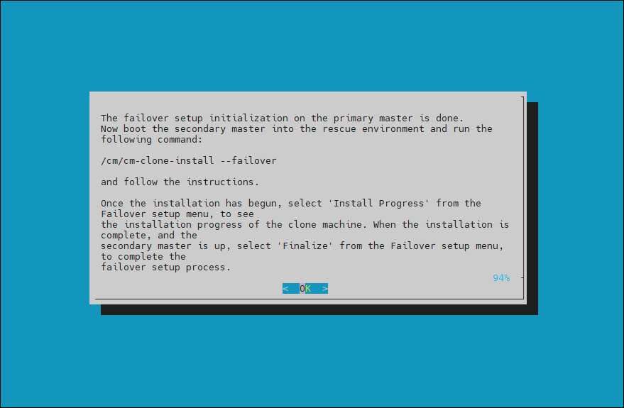
PXE boot the secondary head. Because this is the initial boot of this node, it must be done outside of BCM (BMC or physical power button).
Select RESCUE from the GRUB menu.
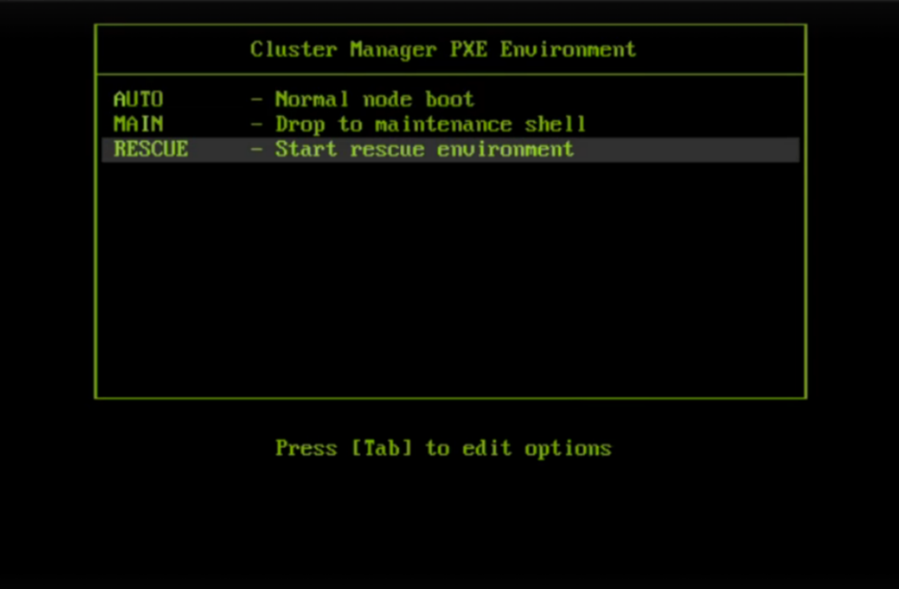
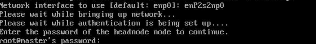
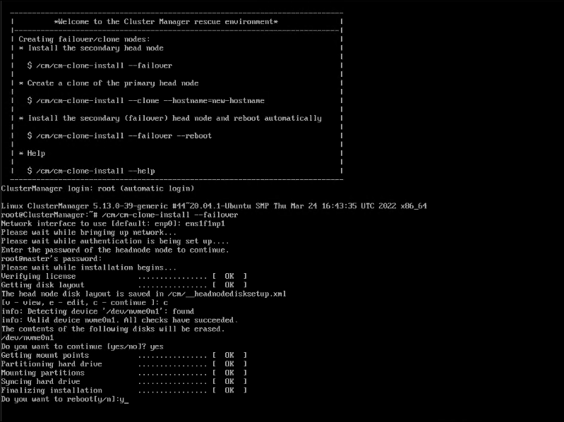
After the secondary head node has boot into the rescue environment, run the
/cm/cm-clone-install --failovercommand.Choose an interface that is the same as on the main head node and enter the head node password.
When prompted for the disk layout, enter c to continue.
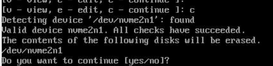
When cloning is complete, enter y to reboot the secondary head node.
Wait for the secondary head node to reboot and then continue the HA setup procedure on the primary head node. setup procedure on the primary head node.
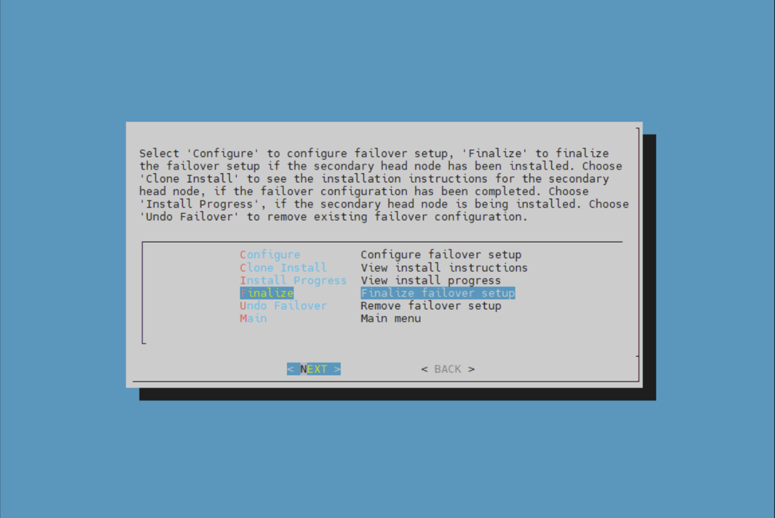
Choose finalize from the cmha-setup menu and then select NEXT. This will clone the MySQL database from the primary to the secondary head node.
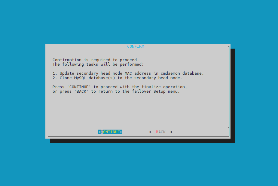
Select CONTINUE on the confirmation screen.
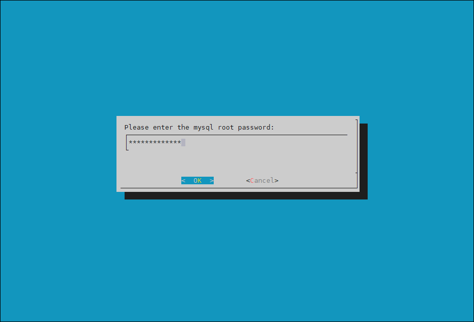
Enter the root password and then select OK.
The cmha-setup wizard continues.
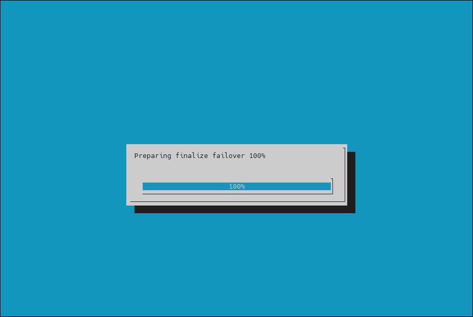
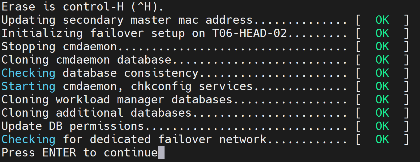
Press ENTER to continue when prompted. The progress is shown in the following image:
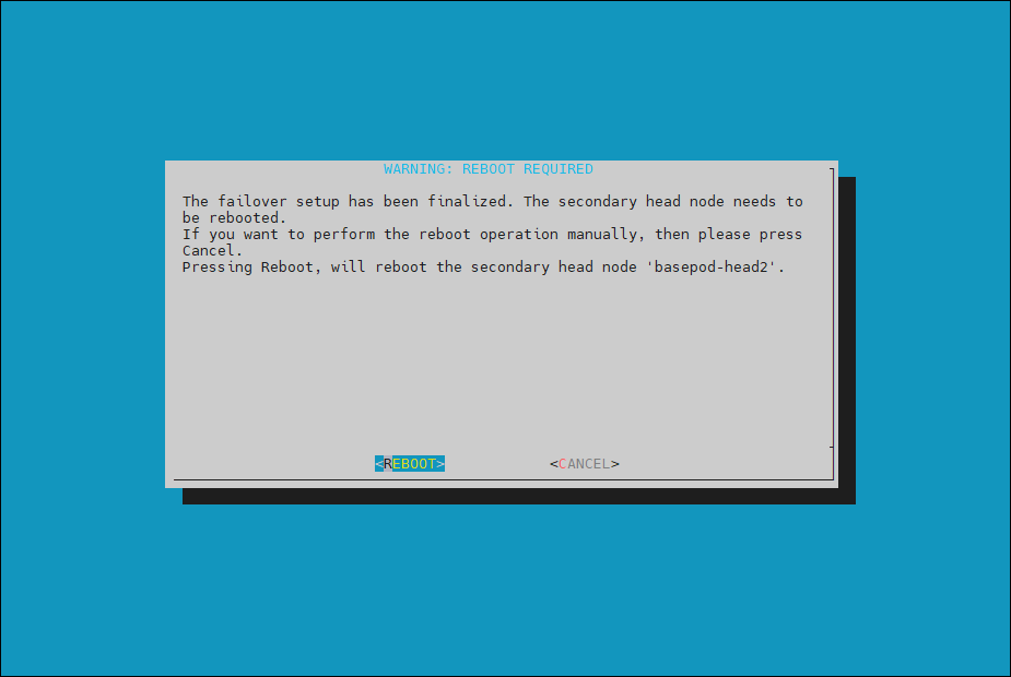
The Finalize step is now completed. Select REBOOT and wait for the secondary head node to reboot.
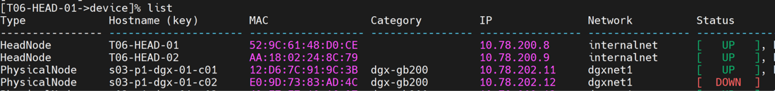
The secondary head node is now “UP”.
Confirm that the HA is functional.
root@T06-HEAD-01:~# cmha status

Node Status: running in active mode

T06-HEAD-01* -> T06-HEAD-02

mysql  [ OK ]
ping   [ OK ]
status [ OK ]

T06-HEAD-02 -> T06-HEAD-02*

mysql  [ OK ]
ping   [ OK ]
status [ OK ]
NFS Configuration#
On the NFS appliance/server:
Set up the NFS appliance to be used on the cluster’s internalnet network. This must be done within the NFS appliance OS. Because DGX SuperPOD does not mandate the nature of the NFS storage, the configuration is outside the scope of this document.
Create two mount points for /cm/shared/ and /home. User home directories (home/) and shared data (cm_shared/) directories are shared between head nodes and must be stored on an NFS filesystem for HA. These mount points on the are what are used in the cmha shared storage setup wizard. It is up to the deployment engineer or person who configures the NFS to decide the export path.
Note
For mixed architecture setups, you need to create three mount points: one for
/homeand two forcm_shared, with a directory for each microarchitecture. For example:/home /shared-ubuntu2404-aarch64 /shared-ubuntu2404-x86_64
The following parameters/mount options are recommended for the NFS server export file
/etc/exports.<EXPORT_PATH>\*(rw,sync,no_root_squash,no_subtree_check
By default, DGX SuperPOD uses NFSv3.
Shared Storage Setup#
From within the cmha-setup wizard:
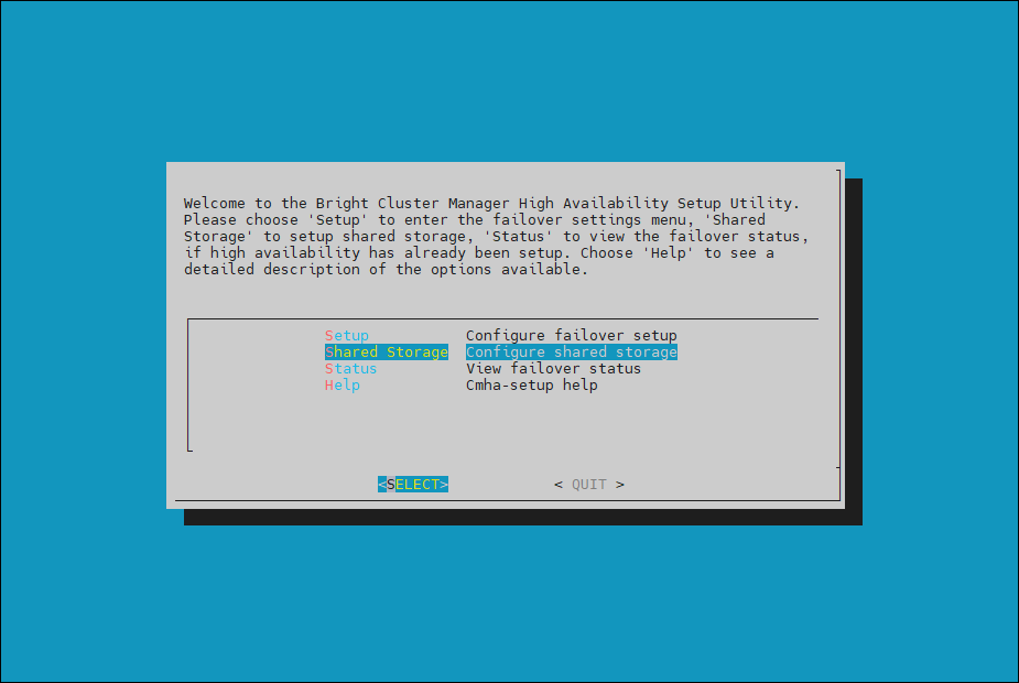
Select Shared Storage from the cmha-setup menu and then select SELECT.
In this final HA configuration step, cmha-setup will copy the
/cm/sharedand/homedirectories to the shared storage and configure both head nodes and all cluster nodes to mount it. Choose NAS and then select SELECT.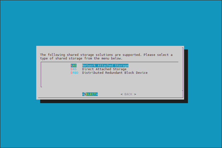
Choose both
/cm/sharedand/homeand then select NEXT.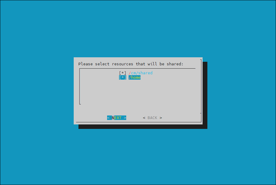
Mixed architecture (default for GB200 clusters) - It is required that all
/cm/shareddirectories for each uarch are shared.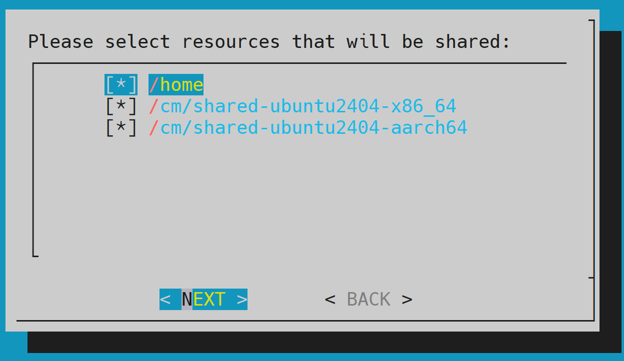
Provide the IP address of the NAS host, the paths that the
/cm/shared-ubuntu2404-aarch64,/cm/shared-ubuntu2404-x86_64and/homedirectories should be copied to on the shared storage, and then select NEXT.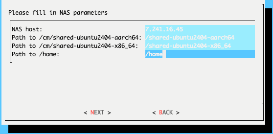
The wizard shows a summary of the information that it has collected. Select EXIT to continue.
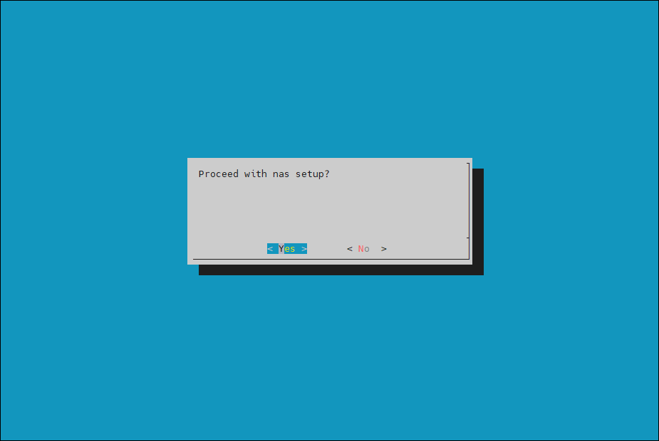
When asked to proceed with the NAS setup, select Yes to continue. This will initiate a copy and make updates to fsexports.
The cmha-setup wizard proceeds with setup.
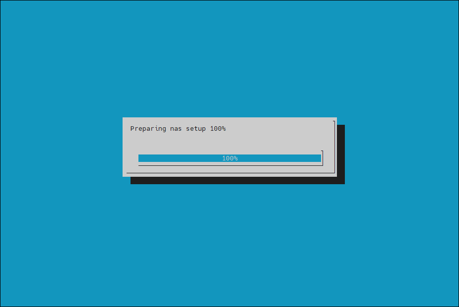
When setup completes, press any key to finish HA setup.
The progress is shown here:

Copying NAS data................................... [ OK ]
Mount NAS storage.................................. [ OK ]
Remove old fsmounts................................ [ OK ]
Add new fsmounts................................... [ OK ]
Remove old fsexports............................... [ OK ]
Write NAS mount/unmount scripts.................... [ OK ]
Copy mount/unmount scripts......................... [ OK ]

Press any key to continue
cmha-setup is now complete. Press EXIT to exit the wizard and return to the shell prompt.
Verify HA Failover Functionality#
Run the
cmha statuscommand to verify that the failover configuration is correct and working as expected.The command tests the configuration from both directions: from the primary head node to the secondary, and from the secondary to the primary. The active head node is indicated by an
*(asterisk).# cmha status Node Status: running in active mode bcm-head-01* -> bcm-head-02 failoverping [ OK ] mysql [ OK ] ping [ OK ] status [ OK ] bcm-head-02 -> bcm-head-01* failoverping [ OK ] mysql [ OK ] ping [ OK ] status [ OK ]
Verify that the
/cm/sharedand/homedirectories are mounted on the NAS server.$ mount ...some output omitted... 7.241.16.39:/cm_shared/ubuntu2404-x86_64 on /cm/shared-ubuntu2404-x86_64 type nfs (rw,relatime,vers=3,rsize=65536,wsize=65536,namlen=255,hard,proto=tcp,timeo=600,retrans=2,sec=sys,mountaddr=7.241.16.39,mountvers=3,mountport=635,mountproto=udp,local_lock=none,addr=7.241.16.39) 7.241.16.39:/home on /home type nfs (rw,relatime,vers=3,rsize=65536,wsize=65536,namlen=255,hard,proto=tcp,timeo=600,retrans=2,sec=sys,mountaddr=7.241.16.39,mountvers=3,mountport=635,mountproto=udp,local_lock=none,addr=7.241.16.39) 7.241.16.39:/cm_shared/ubuntu2404-aarch64 on /cm/shared-ubuntu2404-aarch64 type nfs (rw,relatime,vers=3,rsize=65536,wsize=65536,namlen=255,hard,proto=tcp,timeo=600,retrans=2,sec=sys,mountaddr=7.241.16.39,mountvers=3,mountport=635,mountproto=udp,local_lock=none,addr=7.241.16.39)
Login to the head node to make it active and run
cmha makeactive.# ssh bcm-head-02 # cmha makeactive ========================================================================= This is the passive head node. Please confirm that this node should become the active head node. After this operation is complete, the HA status of the head nodes will be as follows: bcm-head-02 will become active head node (current state: passive) bcm-head-01 will become passive head node (current state: active) ========================================================================= Continue(c)/Exit(e)? c Initiating failover.............................. [ OK ] bcm-head-02 is now active head node, makeactive successful
Run the
cmsh statuscommand again to verify that the secondary head node has become the active head node.# cmha status Node Status: running in active mode bcm-head-02* -> bcm-head-01 failoverping [ OK ] mysql [ OK ] ping [ OK ] status [ OK ] bcm-head-01 -> bcm-head-02* failoverping [ OK ] mysql [ OK ] ping [ OK ] status [ OK ]
Manually failover back to the primary head node by running
cmha makeactive.# ssh bcm-head-01 # cmha makeactive =========================================================================== This is the passive head node. Please confirm that this node should become the active head node. After this operation is complete, the HA status of the head nodes will be as follows: bcm-head-01 will become active head node (current state: passive) bcm-head-02 will become passive head node (current state: active) =========================================================================== Continue(c)/Exit(e)? c Initiating failover.............................. [ OK ] bcm-head-01 is now active head node, makeactive successful
Run the
cmsh statuscommand again to verify that the primary head node has become the active head node.# cmha status Node Status: running in active mode bcm-head-01* -> bcm-head-02 failoverping [ OK ] mysql [ OK ] ping [ OK ] status [ OK ] bcm-head-02 -> bcm-head-01* failoverping [ OK ] mysql [ OK ] ping [ OK ] status [ OK ]
Power on the cluster nodes.
# cmsh -c "device ; power -c dgx-gb200 on"

ipmi0 .................... [ ON ] a05-p1-dgx-01-c01
ipmi0 .................... [ ON ] a05-p1-dgx-01-c02
ipmi0 .................... [ ON ] a05-p1-dgx-01-c03
ipmi0 .................... [ ON ] a05-p1-dgx-01-c04
This concludes the setup and verification of HA.
Post HA and NFS Configuration Steps#
These tasks need to be performed to ensure the cluster behaves correctly when running in High Availability mode with the NFS appliance operational.
Mixed Architecture Fsmounts Configuration#
For all categories, the fsmounts need to be configured to align with their respective microarchitecture after HA + Shared Storage Setup.
As an example, the fsmounts may look like the following:
[a17-p1-bcm-01->category[gb200]->fsmounts]% list

Device                        Mountpoint (key)                Filesystem
----------------------------- -------------------------------- ----------------
none                          /dev/pts                        devpts
none                          /proc                           proc
none                          /sys                            sysfs
none                          /dev/shm                        tmpfs
$localnfsserver:$cmshared     /cm/shared                      nfs
172.16.2.11:/mnt/raid         /home                           nfs
172.16.2.11:/mnt/cm/shared/aarch64/cm/shared-ubuntu2404-aarch64 nfs
172.16.2.11:/mnt/cm/shared/x86/cm/shared-ubuntu2404-x86_64    nfs
Note
The
/cm/shareddevice is incorrect and there are two/cm/shared-*mounts. The following steps will correct these mounts.Remove the default
/cm/sharedentry that has the filesystem$localnfsserver:$cmshared:% cmsh % category use <CATEGORY_BEING_MODIFIED> % fsmounts % remove /cm/shared % commit
Remove the
/cm/shared-ubuntu2404-<UARCH>entry where<UARCH>is the opposite microarchitecture of the category. For the GB200 category, this will bex86_64.% cmsh % category use <CATEGORY_BEING_MODIFIED> % fsmounts % remove /cm/shared-ubuntu2404-<UARCH> % commit
Add the correct
/cm/sharedentry.# Example: aarch64 /cm/shared entry % cmsh % category use <CATEGORY_NAME> % fsmounts % set <NAS_HOST_IP>:/cm/shared-ubuntu2404-aarch64 mountpoint /cm/shared % set filesystem nfs % commit # Example: x86 /cm/shared entry % cmsh % category use <CATEGORY_NAME> % fsmounts % set <NAS_HOST_IP>:/cm/shared-ubuntu2404-x86_64 mountpoint /cm/shared % set filesystem nfs % commit
A correct example of this would look like the following for the control plane and GB200/GB300 nodes:
[a03-p1-head-01->category[slogin]->fsmounts]% list

Device                        Mountpoint (key)                Filesystem
----------------------------- -------------------------------- ----------------
none                          /dev/pts                        devpts
none                          /proc                           proc
none                          /sys                            sysfs
none                          /dev/shm                        tmpfs
7.241.16.39:/cm_shared/ubuntu2404-aarch64 /cm/shared          nfs
7.241.16.39:/home             /home                           nfs


.. code-block:: console
   :caption: Example: GB200/GB300 category fsmounts

   [a17-p1-bcm-01->category[dgx-gb200]->fsmounts[/cm/shared]]% list

   Device                        Mountpoint (key)                Filesystem
   ----------------------------------- ------------------------------- ----------------
   none                          /dev/pts                        devpts
   none                          /proc                           proc
   none                          /sys                            sysfs
   none                          /dev/shm                        tmpfs
   172.16.2.11:/mnt/raid         /home                           nfs
   172.16.2.11:/mnt/cm/shared/aarch64/cm/shared /cm/shared       nfs

.. note::

   The above example assumes that this node is an ARM/aarch64 node. If it is x86, then it would be /cm_shared/ubuntu2404-x86