Camera Calibration
Overview
The Metropolis Camera Calibration Toolkit offers guidance for setting up and calibrating cameras for Metropolis Apps and Microservices integration. Designed as a React/Python web application, this toolkit assists NVIDIA developers in seamlessly onboarding their cameras. Once calibrated, these cameras can be exported for use with Metropolis Apps or Microservices.
The software facilitates the onboarding of cameras, calibration, defining regions-of-interest (ROIs), setting virtual tripwires, and validating the entire process. Through camera calibration, the output from the sensor-processing layer is accurately mapped onto a real-world coordinate system.
Prerequisites
Hardware Requirements
8 GB system RAM
2 core CPU
50 GB of HDD space
Recommended
16 GB system RAM
4 core CPU
100 GB of SSD space
Software Requirements
OS Independent – Recommended: Ubuntu 20.04 LTS
Browser - Recommended: Google Chrome
Installation Requirements
Sample frames/screenshots from each camera stream
Building map or floor plan (top-down 2D schematic drawing of the location covered by cameras)
Installation
Pull the docker from NGC:
docker pull nvcr.io/nfgnkvuikvjm/mdx-v2-0/mdx-calibration:2.1
Make a directory to store your data:
mkdir <path/to/dir>/data
Run the docker container using host’s port 8003, and mounting the aforementioned directory as your data folder.
docker run -p 8003:8003 -v <path to data dir>/data:/calibration/server/data/ -it nvcr.io/nfgnkvuikvjm/mdx-v2-0/mdx-calibration:2.1 deploy.sh 8003
Note
You may add network=host to the docker command if you have problem running the containers.
Navigate to http://[localhost-or-remote-IP]:8003, where the application will be live. In K8s deployment, navigate to http://[localhost-or-remote-IP]:31080/calibration
Project Setup
In this section we will learn how to setup the structures that will eventually create the configs for the Metropolis Apps or Microservices.
Project Configuration
First, we will create a project. There’s different project type:
Cartesian Calibration - Approximate cartesian calibration for a single camera
Multi-Camera Tracking Calibration - Calibration for multi-camera tracking based on a single floor plan
Image Calibration - Only ROI/tripwire calibration for images
After choosing the type, enter the project to start calibrating.
Note
Cartesian Calibration is used for Occupancy Analytics (OA) reference app and Multi-Camera Tracking Calibration is used for Multi-Camera Tracking reference app. Fundamental difference between those two are: Multi-Camera Tracking Calibration is with a floor plan map, while Cartesian Calibration is without one.
When you do have a floor plan map, reference points are selected from camera view and plan map, which is straight forward. But when you don’t have plan map, you would need to imagine a top-down view as the floor plan while selecting the reference points from camera view. So (for advanced users) if you have a floor plan for your OA app, you can use Multi-Camera Tracking Calibration (aka calibration with floor plan) for your OA app.
Import Project
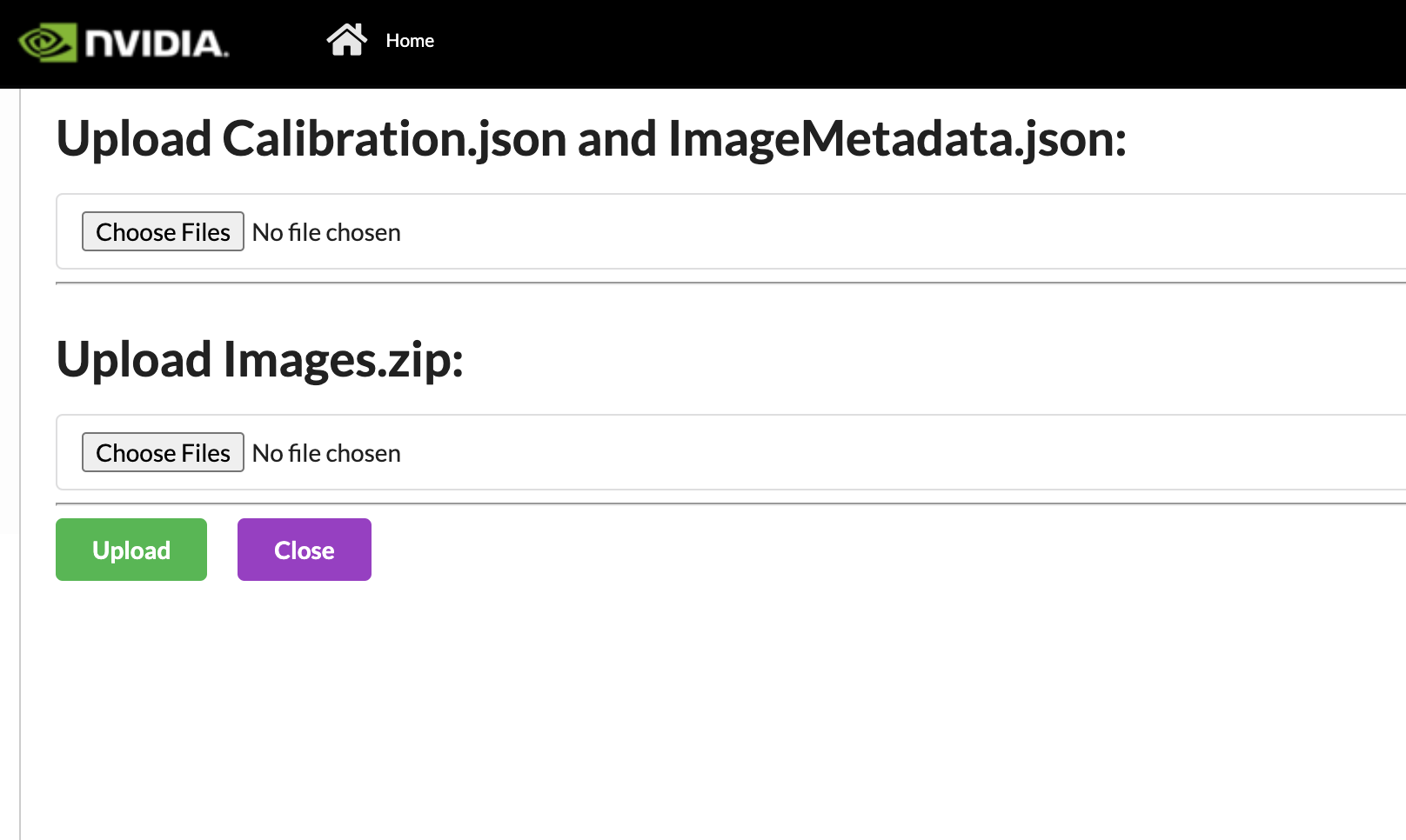
We can also can import projects that were exported from previous deployments (1.1 onwards). First, upload the calibration.json and the imageMetadata.json. The naming must match to be uploaded. Then we will upload the Images.zip which also comes from the export. It may take some time for the images upload to happen. Please wait for the green Zip file uploaded before pressing the Upload button. If the project already exists, the naming will be changed to reflect that it is unique. Also, if a project named “_” is created as a temporary project and does not auto delete, it will block all new imports. Please ensure no project is named “_”, before importing.
Sensor Discovery
The first step is to add cameras. If you have set up VST, you can import the available sensors and propagate some of the sensors details available. If possible, it will also try and take screenshots of the current camera view. This will save time from importing it manually. It may take some time for the sensors to be imported.
The URL templates are shown below:
For VMS: * Standalone:
http://<VST_IP>:30000/* K8s Deployment Non Hosted:http://<HOST_IP>:31080/vms/* K8s Deployment Hosted:http://vms-vms-svc:30000/For NVSTREAMER: * Standalone:
http://<NVSTREAMER_IP>:31000/* K8s Deployment Non Hosted:http://<HOST_IP>:31080/nvstreamer/* K8s Deployment Hosted”http://nvstreamer-nvstreamer-svc:31000/
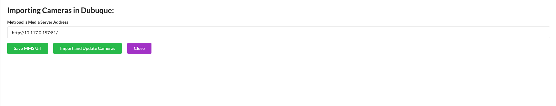
Otherwise, create new sensors in the Setup sensor page.
Sensor Configuration
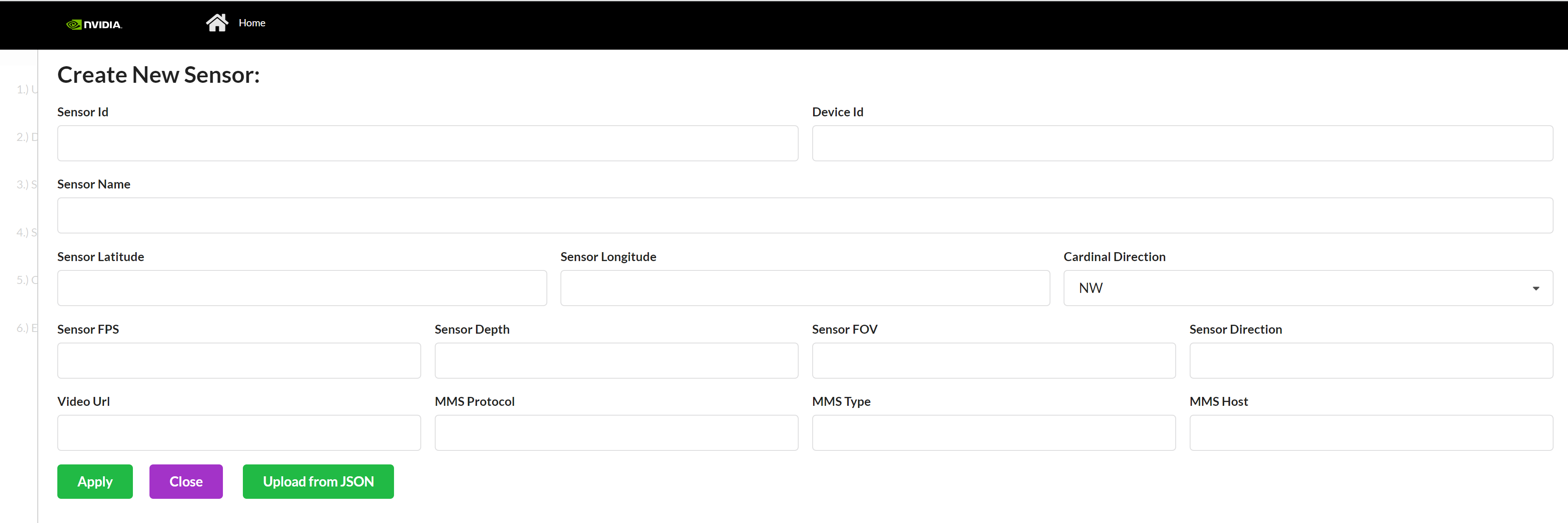
A sensor consists of the metadata that we will be calibrating. These are the common cameras:
Sensor Id* - Sensor ID is the unique name of the sensor, which will be used throughout Metropolis microservices.
Camera Name* - A name that can be used to find the camera in Media Server or ONVIF id
Camera Latitude* - Latitude of Sensor. Range (-180, 180) but cannot be 0.
Camera Longitude* - Longitude of Sensor. Range (-85, 85) but cannot be 0.
Cardinal Direction - Direction of the cars, the Camera’s Field of View sees. For example, if a camera is facing south, the camera’s Field of View is North Bound or NB.
FPS* - Integer referring to Sensor’s Frame per second
Direction - Integer between 0 and 360, measured in degrees, with 0 as North. In Multi-Camera Tracking and People Analytics reference App this is not required, please input 0 as the value.
Depth* - Integer referring to Sensor’s Depth. In Multi-Camera Tracking and People Analytics reference App this is not required, please input 0 as the value.
FOV* - Angle of the Sensor. In Multi-Camera Tracking and People Analytics reference App this is not required, please input 0 as the value.
Video URL* - hls or webRTC URL used by Metropolis microservice UI
MMS Protocol* - 2 options “
webrtc” or “hls”. Use the exact spelling.MMS type* - 2 options “
nvMms” if you are using MMS, or “wowza”. Use this exact spelling.MMS Host* - http URL that points to the Media Server. Be sure to include “
http://” and if you are using MMS, include port 81.
*required
Drawing Guideline
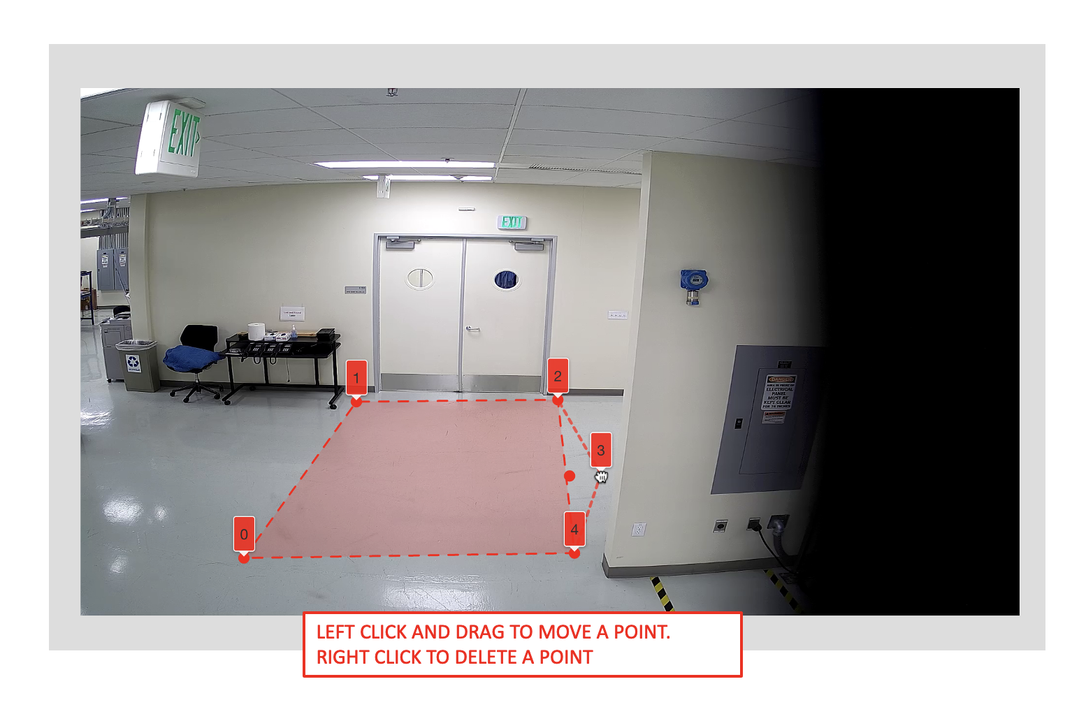
Drawing polygons and polylines in both the image space and map space/floor plan is a key feature in this app. The features for drawing polygons and polylines are essentially the same, the only difference being if the first and last points are connected. We will cover the instructions to draw both polygons and polylines below.
Important: The best practice is to start drawing from the bottom left of the image, and to add points in a counter-clockwise fashion.
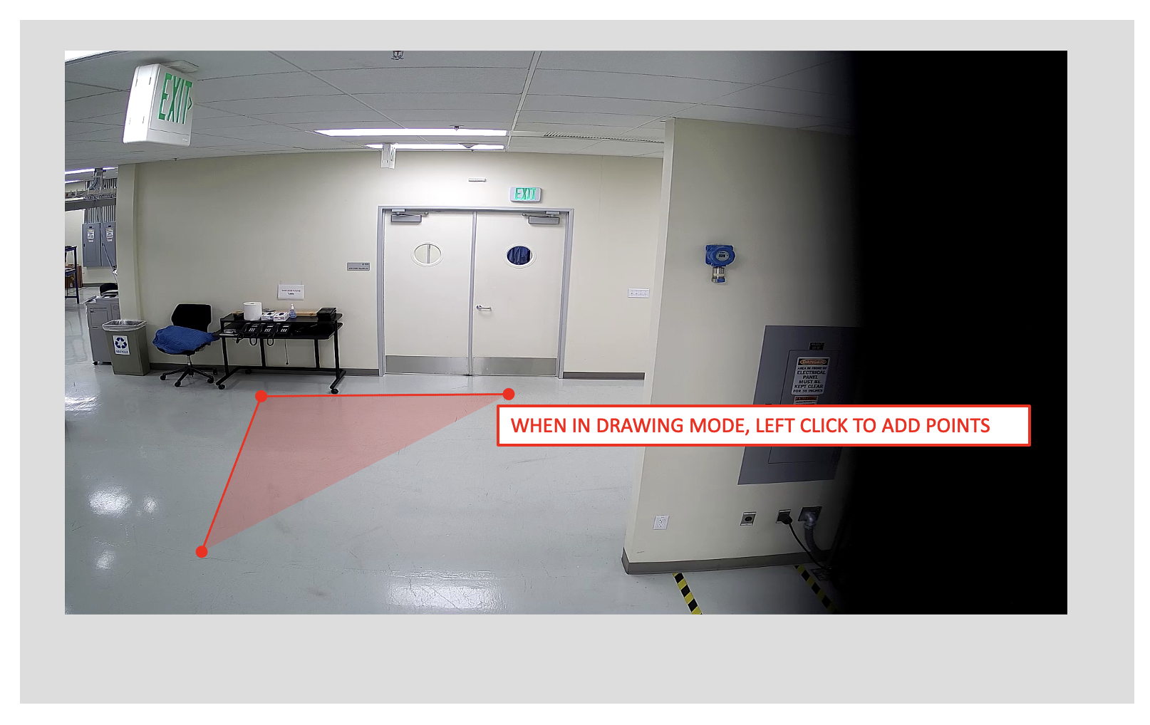
The image drawing container has pan and zoom capabilities. When in a drawing mode, left click on the image to draw and add points.
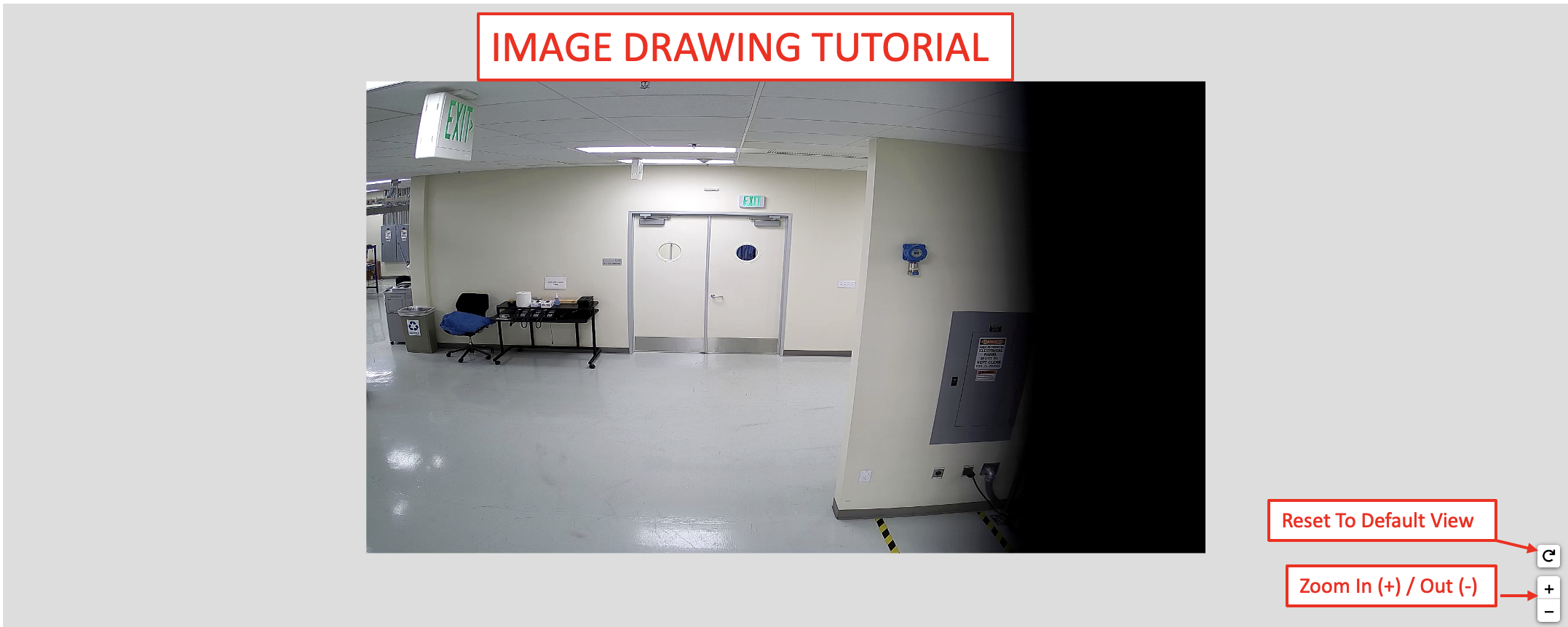
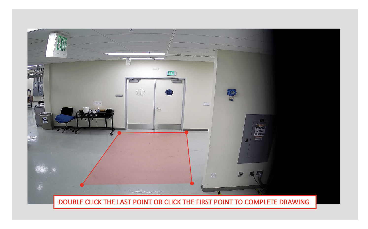
A polygon can be completed using either option below. A polyline can be completed using the endpoint option only.
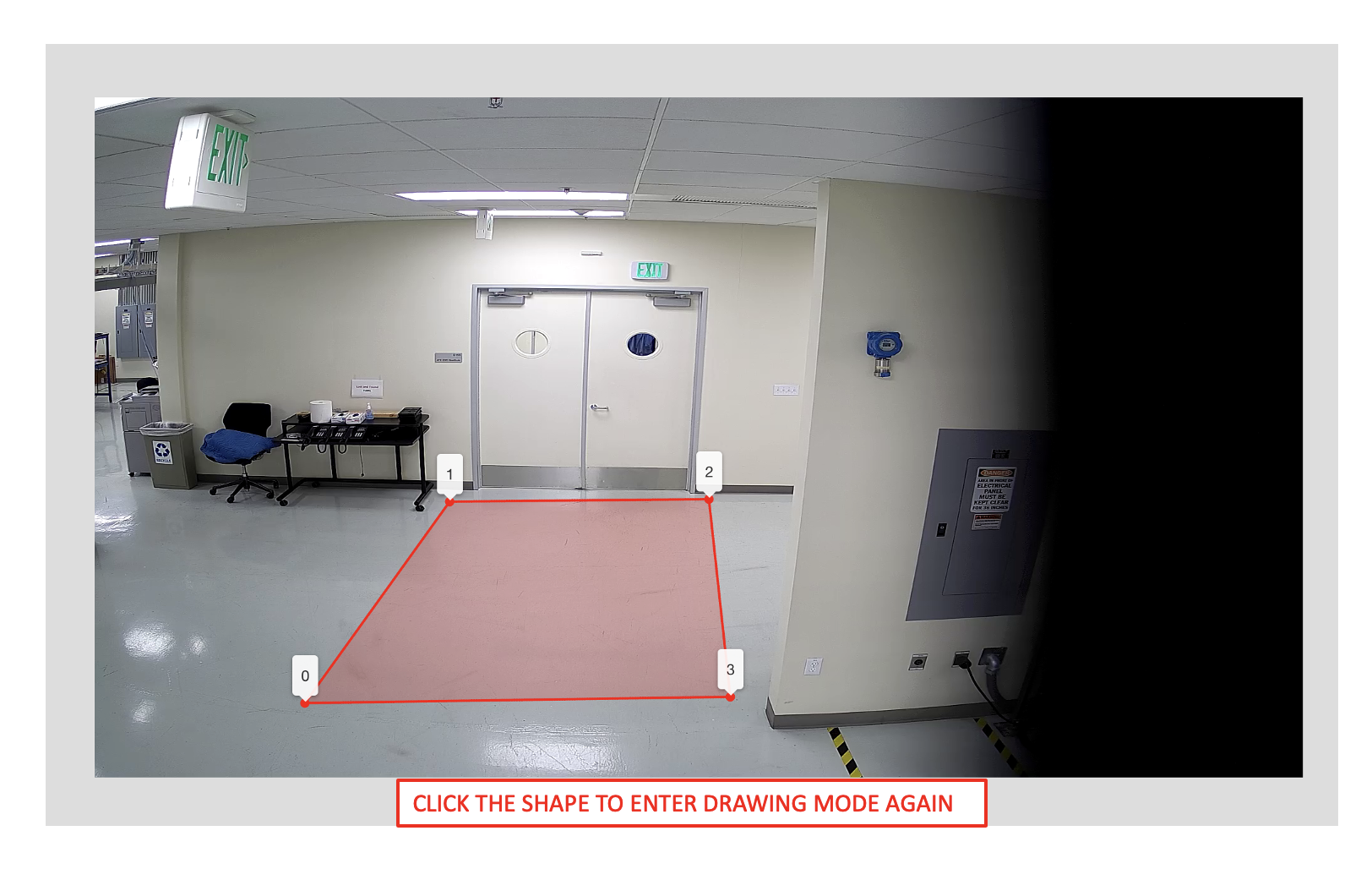
The shape will be saved upon completion. You can then click the shape to enable the edit mode.

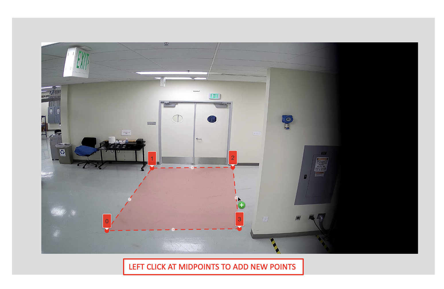
Polygons and polylines have the same capabilities of adding, moving, and deleting points.
Project Type - Multi-Camera Tracking
Multi-camera Tracking Calibration allows us to define a 1:1 mapping between a camera and a floor plan or building map. In this type of calibration, we will use at least 8 points in the pixel space and matching 8 points in the floor plan domain to calibrate sensors. We will calibrate a sensor to a crop of the floor plan that corresponds to that sensor.
Floor Plan Setup
Upload a floor plan of the place being calibrated. This will be used to make sure the correlation between camera and floor plan is consistent. After uploading a floor plan and importing the cameras, the sensors need to be placed on the floor plan. After uploading a floor plan, it may take some time for the floor plan to sync across all cameras. During this time, you will not be able to upload a new floorplan.
For each sensor, place a sensor on it’s location on the floor plan.
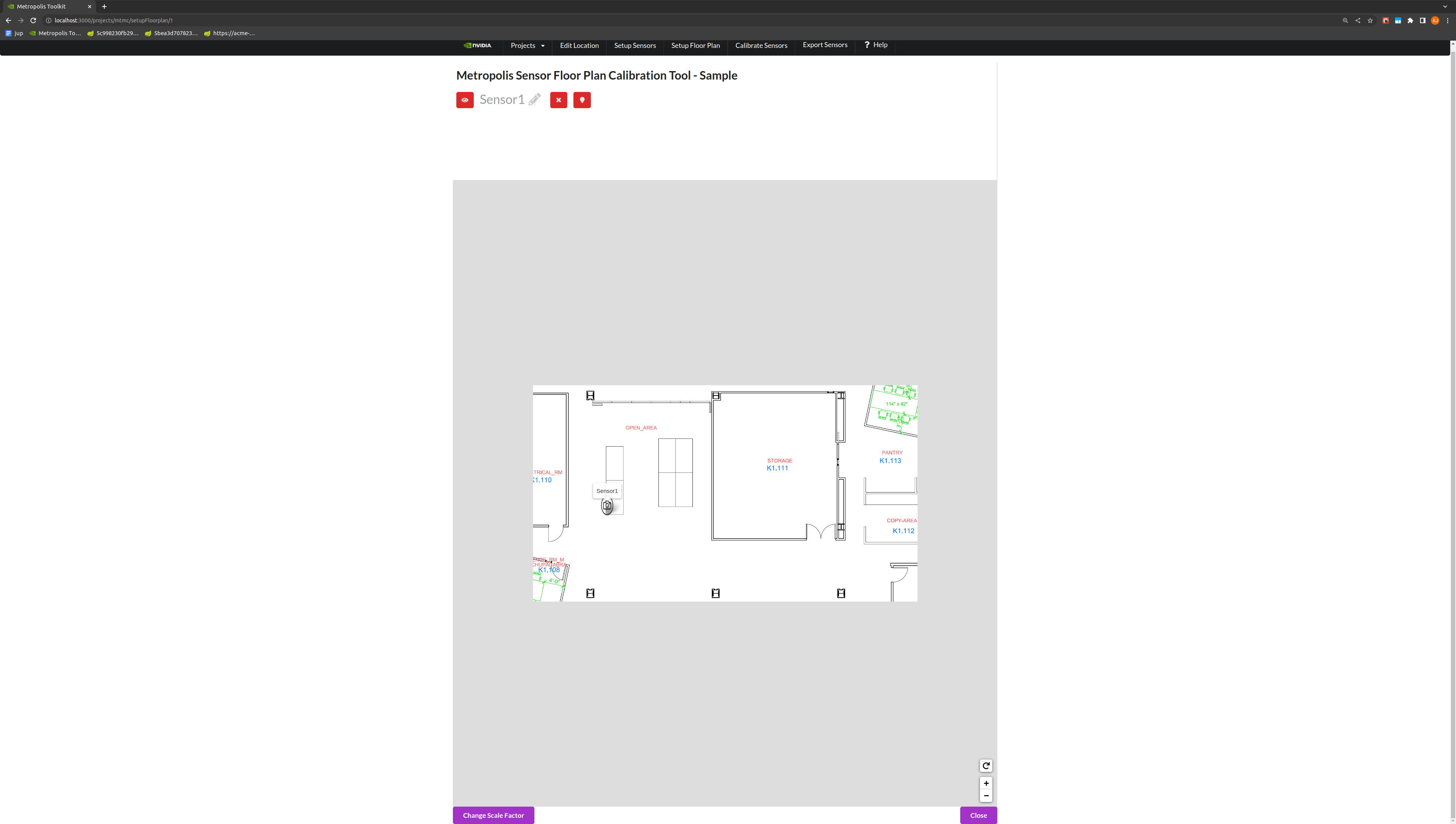
Toggle the Change Scale Factor button, to add a Scale Factor between pixels to meters.
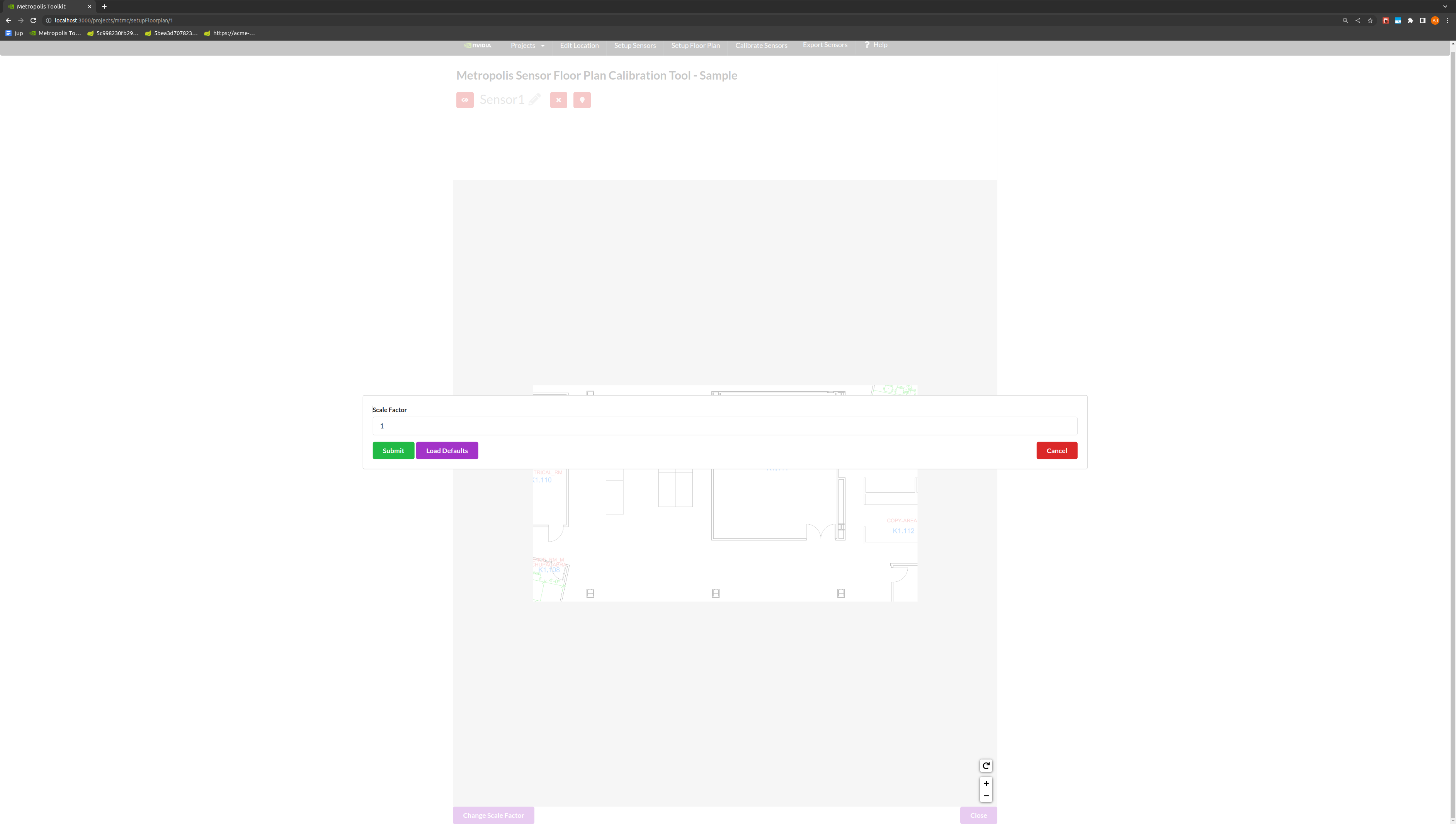
Note
The global coordinates in the final calibration output file is suppose to be in “meters” and the scale factor is “pixel/meters”. Global coordinates in meters is for providing the analytics-streams ease to calculate distances between objects and other metrics. Scale factor is for UI to scale the “meters” back to floor plan pixel scale for visualization.
Use the toggle markers button for better visibility on the exact location of a point.
Calibration
Generate Homography Matrix
Draw a polygon of at least 8 landmark features that can be seen in both the image and the floor plan view. The best practice is to start drawing from the bottom left of the image, and to add points in a counter-clockwise fashion.
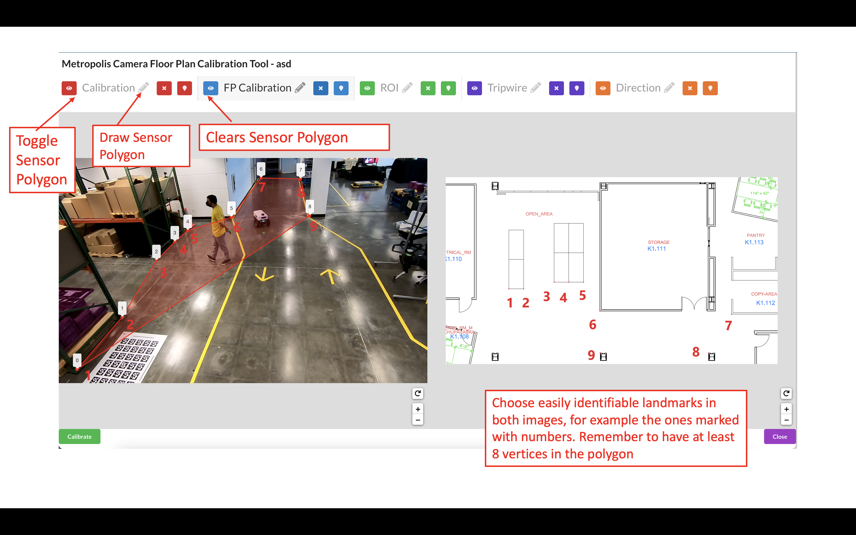
Draw a polygon on the Multi-Camera Tracking floorplan map with landmark features that match the polygon in the image.
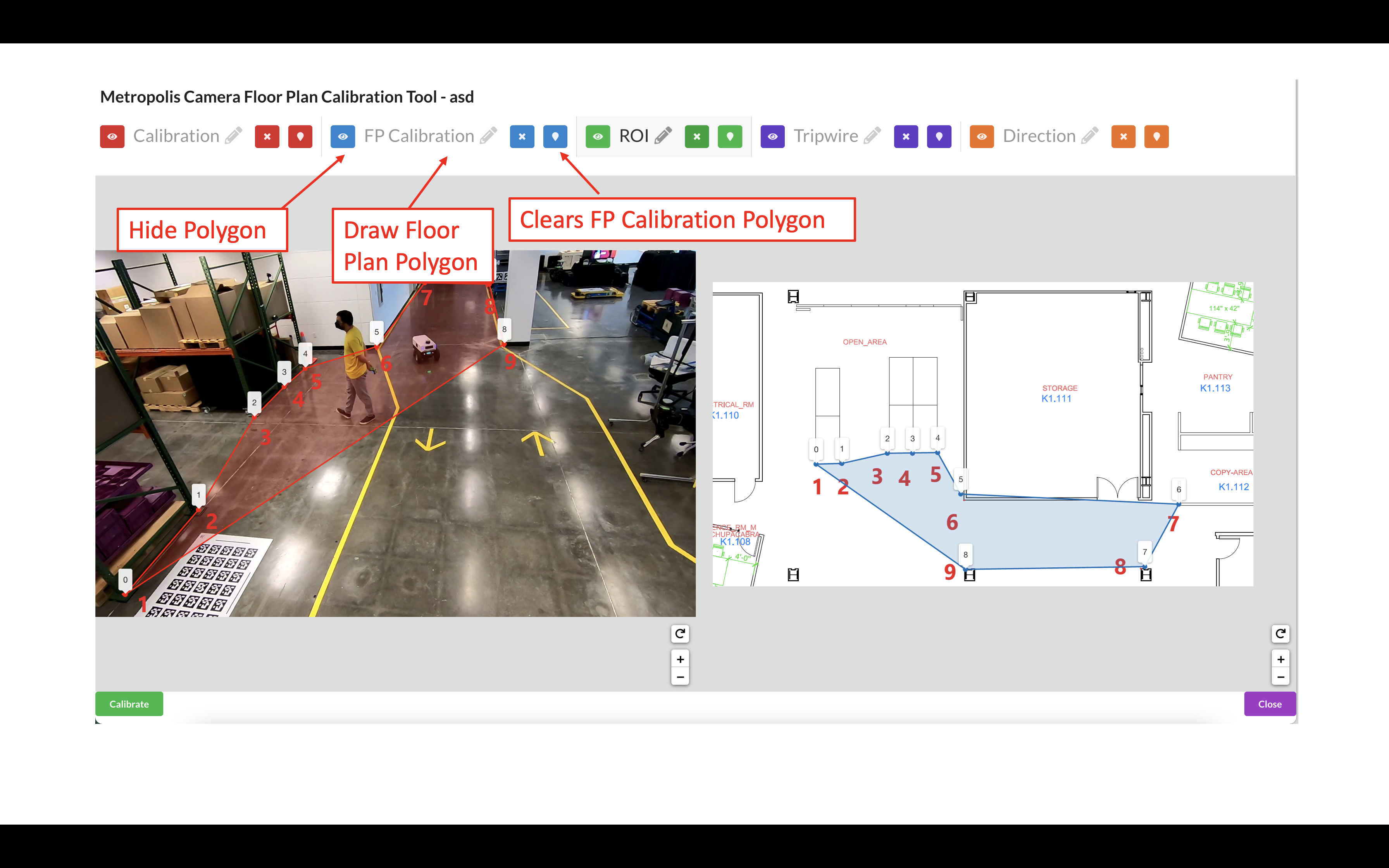
Use the toggle markers button for better visibility on the exact location of a point.
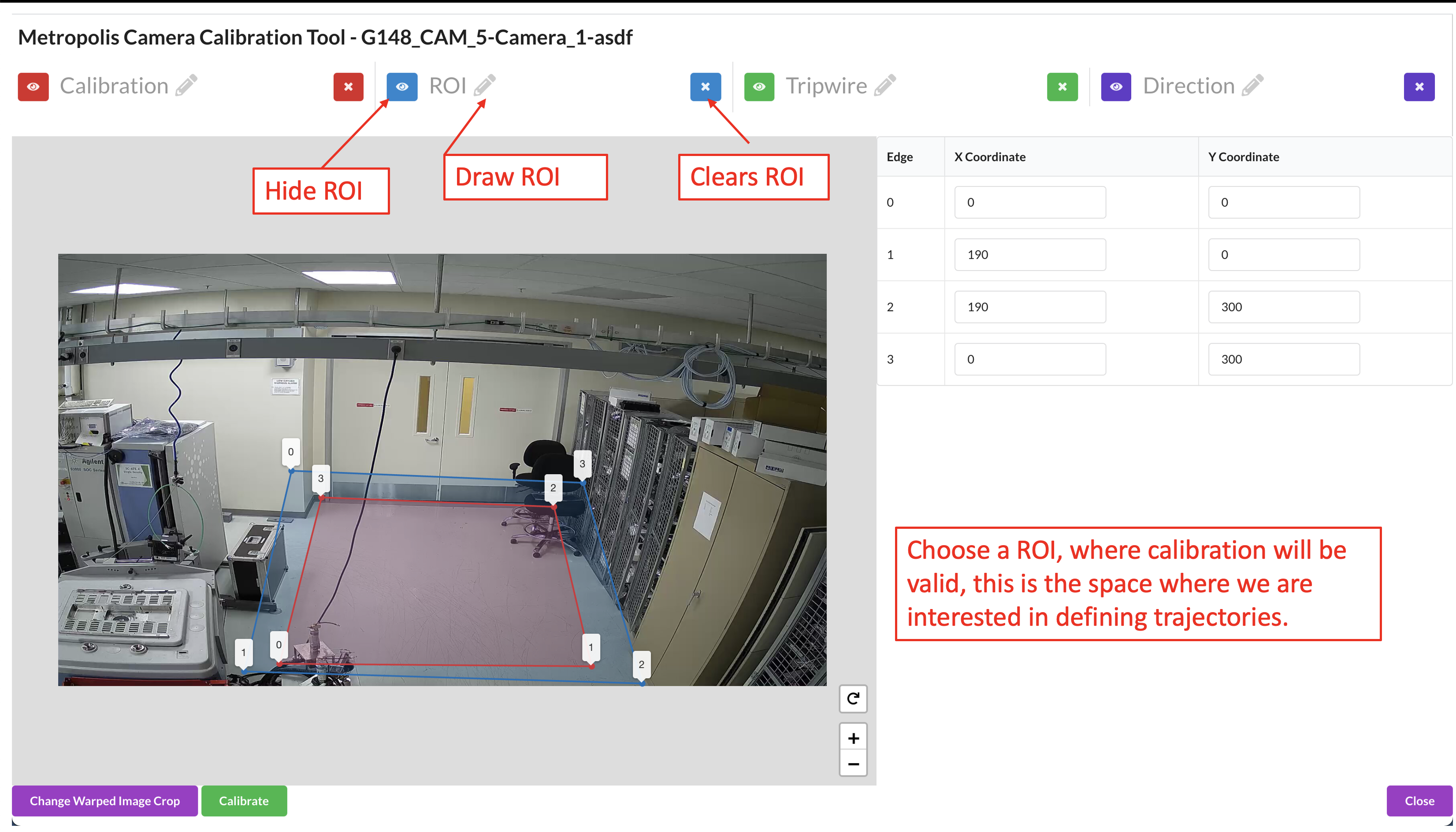
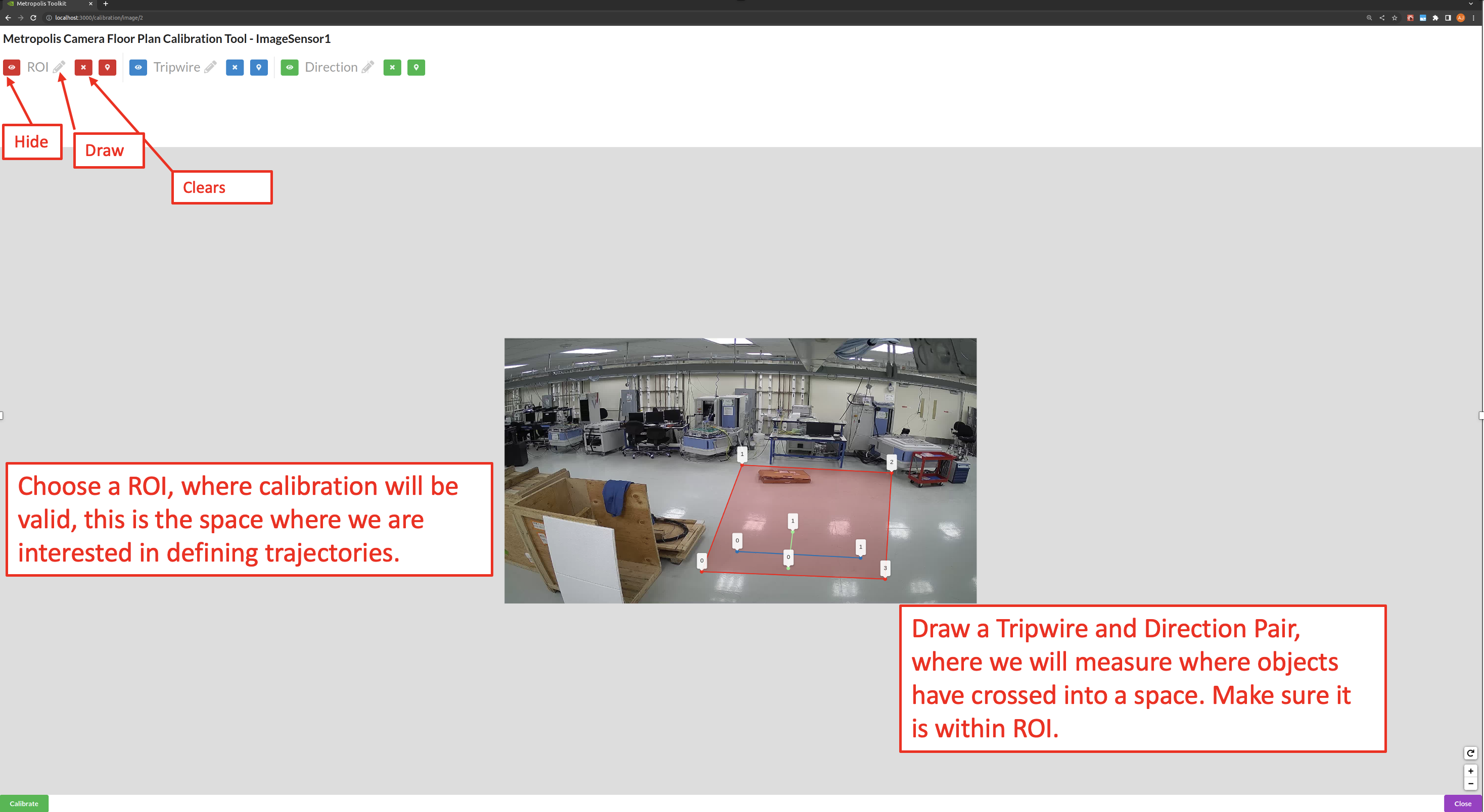
Draw the Region of Interest (ROI), which represents the area for which the calibration is intended to be valid. This does not necessarily have to be the sensor’s entire Field of View.
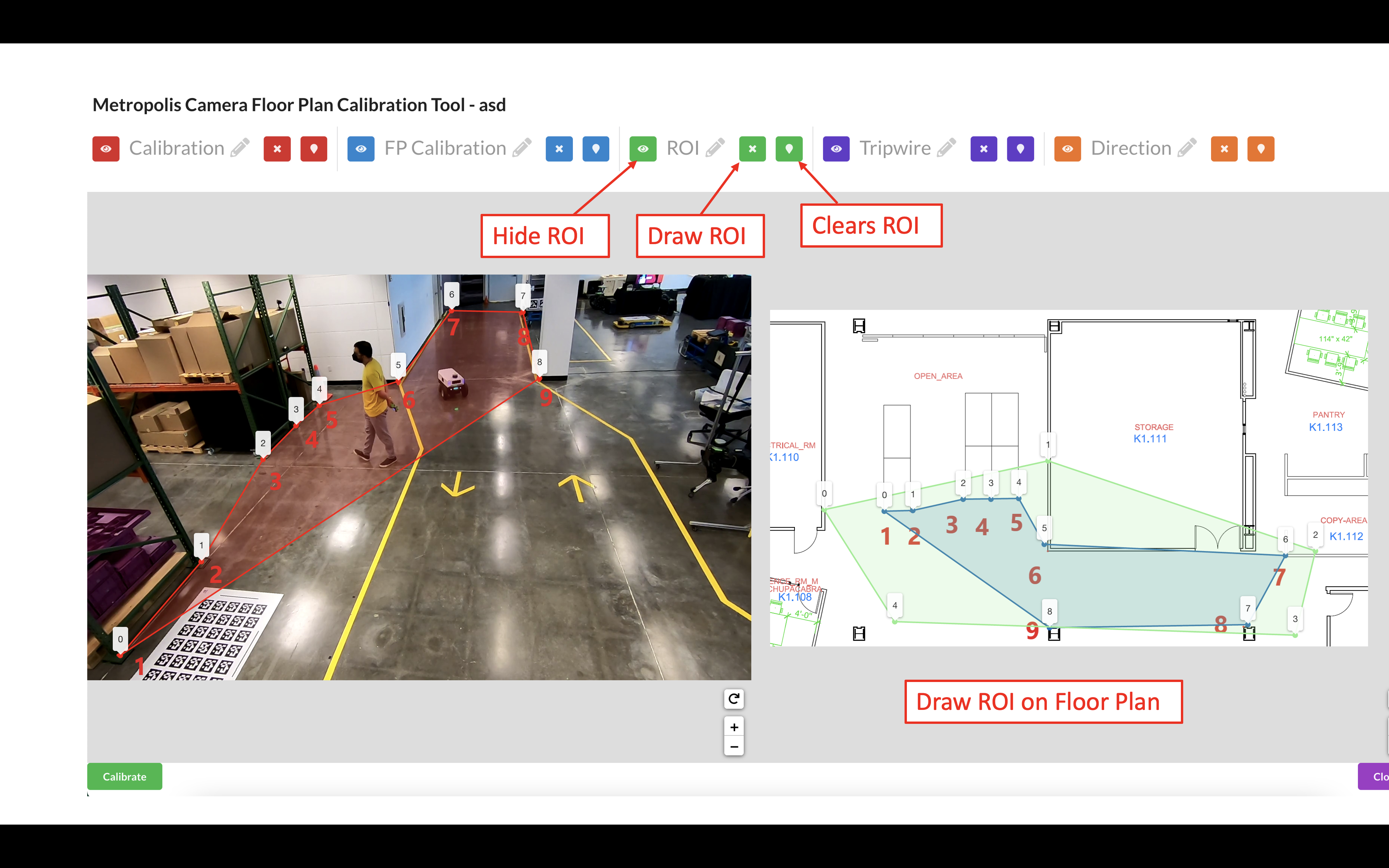
Further notes on the Region of Interest (ROI): The homography matrix from the calibration relies on the assumption that the area is flat, and so the calibration is expected to produce erroneous results in non-planar areas. Therefore, the ROI should cover the parts of the room that the camera can see, so the end application knows to ignore points outside this region. This helps prevent errors and improve performance. The ROI can be further adjusted at the Camera Validation step as the user will learn more about how well the calibration works in certain areas of the image.
Use the toggle markers button for better visibility on the exact location of a point, or to hide the specified polygon or polyline.
Click the Calibrate button to calculate the homography matrix.
Review the reprojection errors of the points. Click edit to go back and adjust points, or Accept Calibration to accept the homography matrix.
More on reprojection error: It is calculated by finding the Euclidean distance between the point and it’s corresponding projected point. The distance (meters) between that point, and the corresponding point drawn on the floor plan/map image (point 1 on the real world image in the case that point 1 on the image polygon was projected to the floor plan coordinates), is the reprojection error for that point correspondence.
Add Tripwires/Direction
Tripwires/Directions are not used by the Multi-Camera Tracking reference app. For Multi-Camera Tracking app you can skip the step of configuring tripwires in calibration toolkit (please do read the important notes under the following Multi-Camera Tracking Validation section).
(For advanced users) If you have a floor plan for your Occupancy Analytics (OA) app and want to use Multi-Camera Tracking Calibration (aka calibration with floor plan) to draw tripwire/direction for that OA app, please refer to Adding Tripwires/Direction in Cartesian Calibration section below.
Validation
Validate the Images
Load the Validation Tool.
Draw a trajectory on the image, and validate that the projected polyline makes sense in the transformed image. Feel free to clear the image and try drawing as many trajectories as desired. Validate the Calibration when satisfied.
The ROI, Tripwire, and Direction lines will be projected onto the real world image. To adjust these lines, go back to the Project Type - Multi-Camera Tracking section.
Project Type - Cartesian
Cartesian Calibration allows us to define a 1:1 mapping between a camera and a plane without a pre-defined coordinate system. In this type of calibration, we will use the 4-points in the pixel space and a user defined coordinate system to calibrate sensors. In Cartesian Calibration, you must add a origin latitude and longitude, as well as the name of the city and a room. The origin could be the city’s lat and long.
Calibration
Generate Homography Matrix
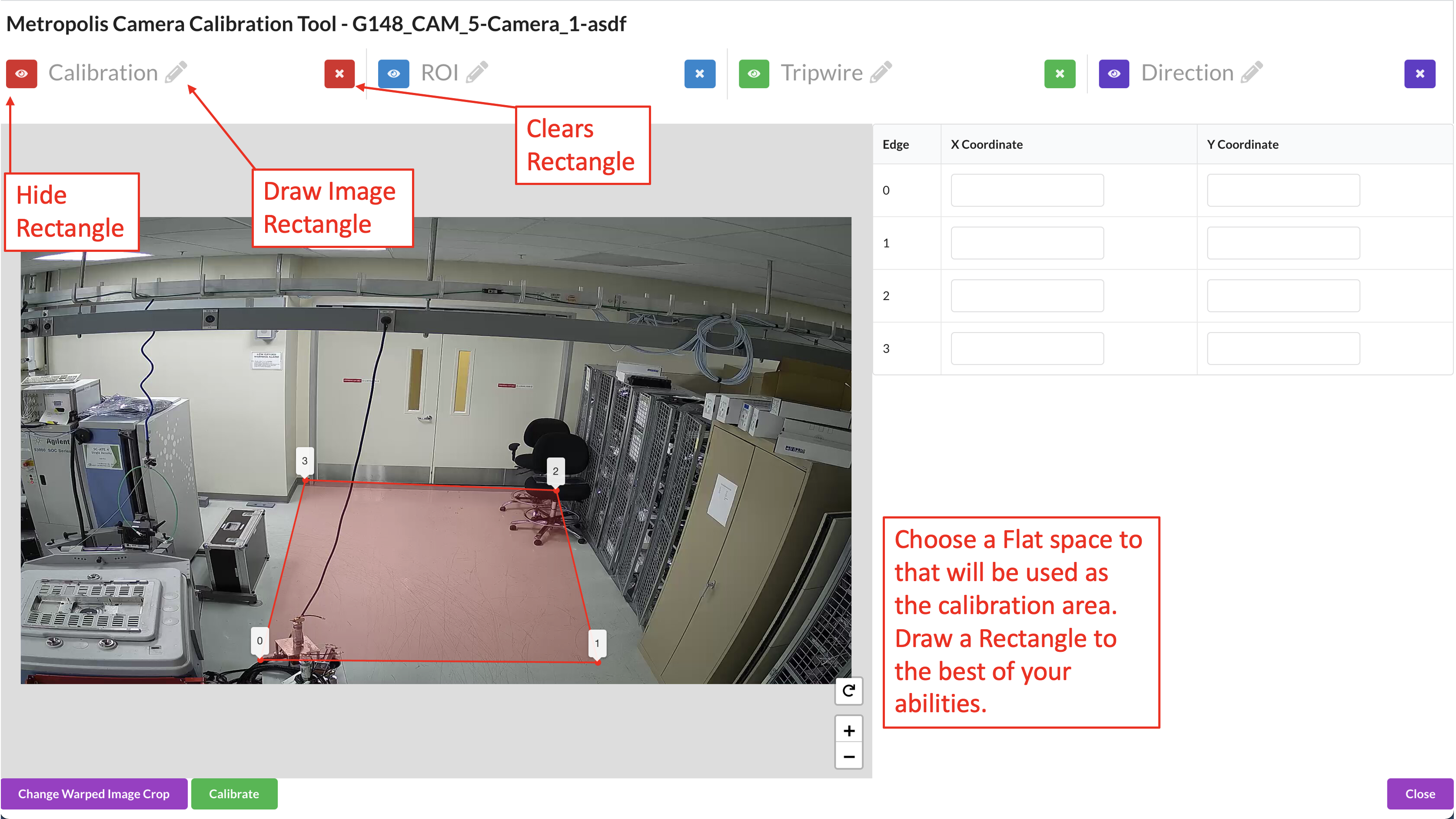
Draw 4-Point Rectangle.
To Generate the camera calibration, the first step is to draw a 4 point rectangle on a flat space in the image. The best practice is to start drawing the rectangle from the bottom left of the image, and to add points in a counter-clockwise fashion.
Define the Cartesian Coordinate System.
On the left side, for each point drawn, you’ll see two boxes with the x and y coordinate which defines that point in the coordinate system. Approximate the distance between the points in centimeters, and define your coordinate system based on the (x,y) distance from your origin.
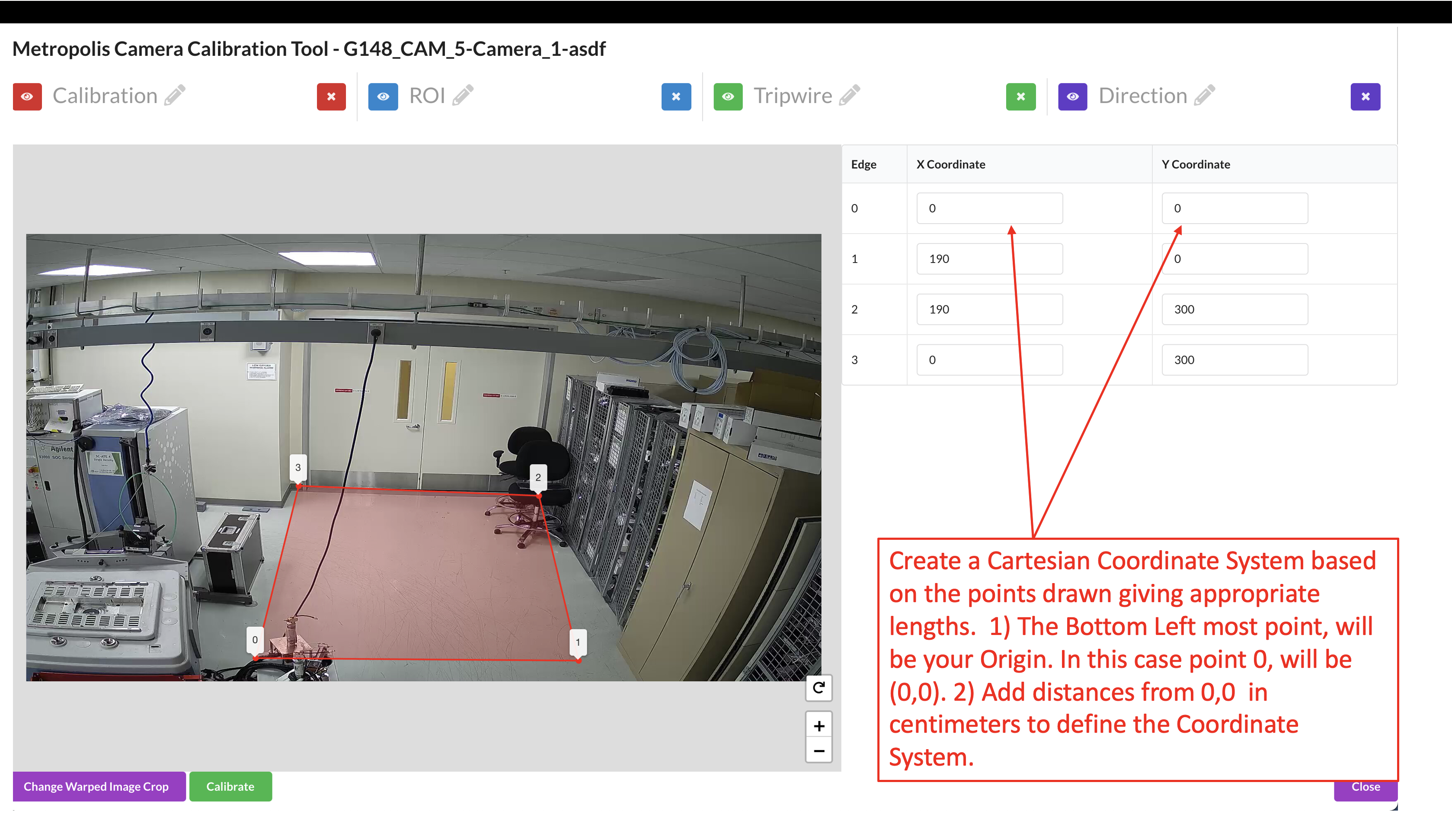
The Bottom Left point will be the first point (0,Y Max), the second point will be (X Max, Y Max), the third point will be (X Max, 0), and the last point, top Right, will be the origin (0,0).
Draw the Region of Interest (ROI), which represents the area for which the calibration is intended to be valid. This does not necessarily have to be the sensor’s entire Field of View.
Further notes on the Region of Interest (ROI): The homography matrix from the calibration relies on the assumption that the floor is flat, and so the calibration is expected to produce erroneous results on stairs, sloped terrain, etc. Therefore, the ROI should cover the parts of the floor that the camera can see, so the end application knows to ignore points outside this region. This helps prevent errors and improve performance. The ROI can be further adjusted at the Sensor Validation step as the user will learn more about how well the calibration works in certain areas of the image.
Use the toggle markers button for better visibility on the exact location of a point, or to hide the specified polygon or polyline.
Click the Calibrate button to calculate the homography matrix.
Review the reprojection errors of the points. Click edit to go back and adjust points, or Accept Calibration to accept the homography matrix.
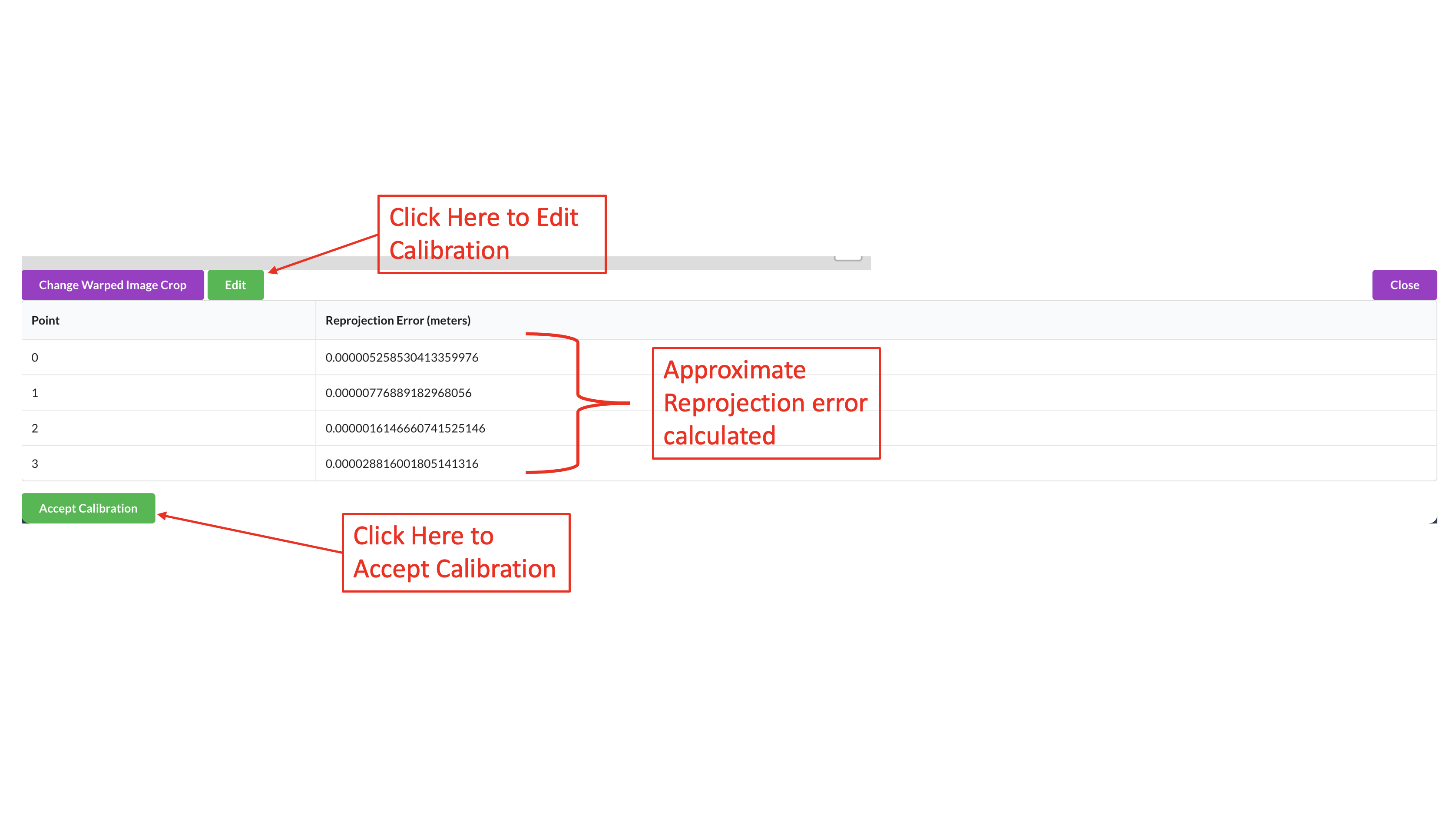
Further notes on reprojection error: The reprojection error is calculated by finding the Euclidean distance between the point and it’s corresponding projected point. The distance (meters) between that point, and the corresponding point drawn on the floor plan/map image (point 1 on the real world image in the case that point 1 on the image polygon was projected to world coordinates), is the reprojection error for that point correspondence.
Add Tripwires/Direction
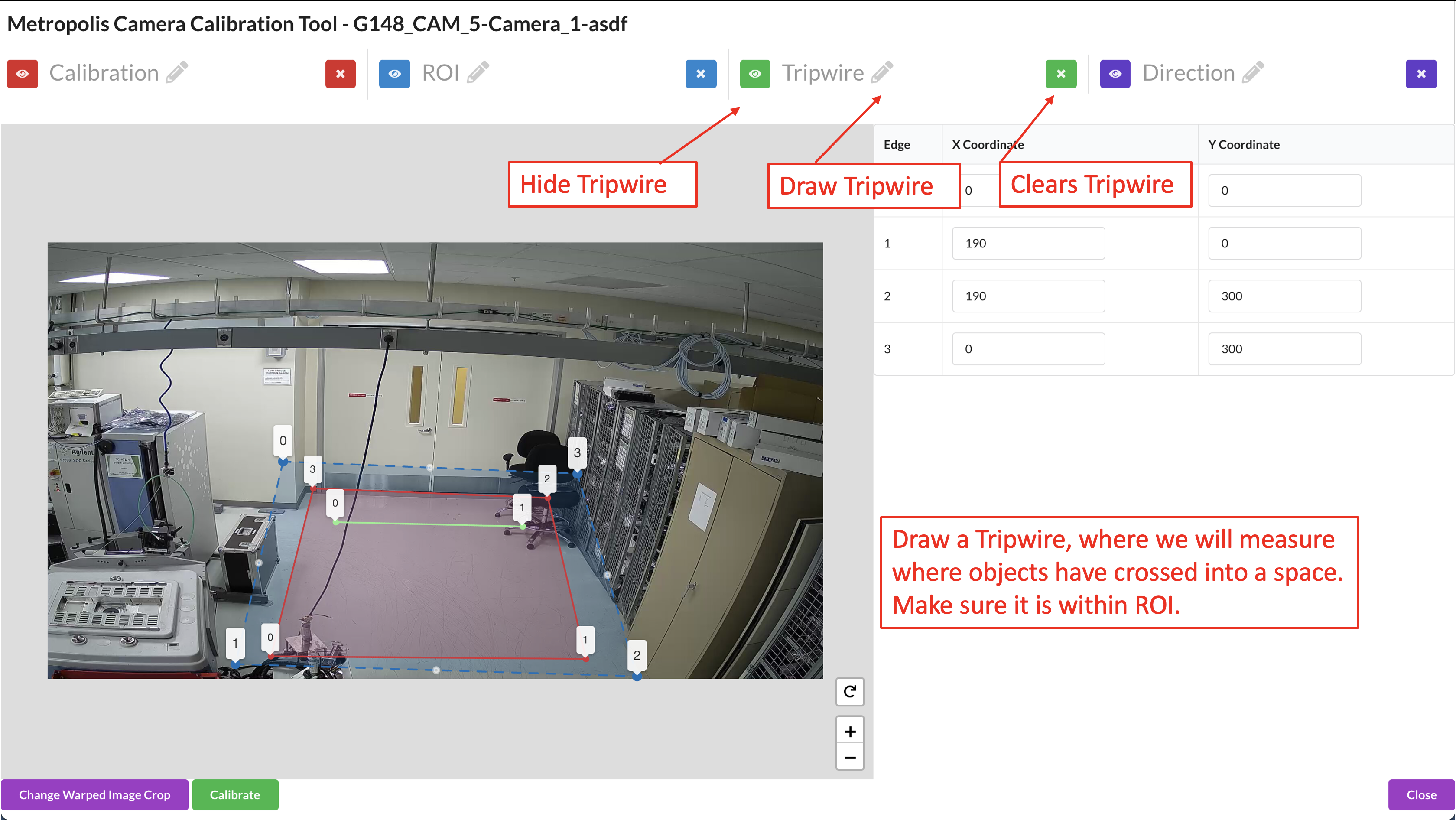
In cartesian calibration, we are able to add tripwires to enable counting.
Draw the tripwire.
Draw a line segment that defines the region where we want to detect if objects have crossed. Make sure that the polyline has only 2 points.
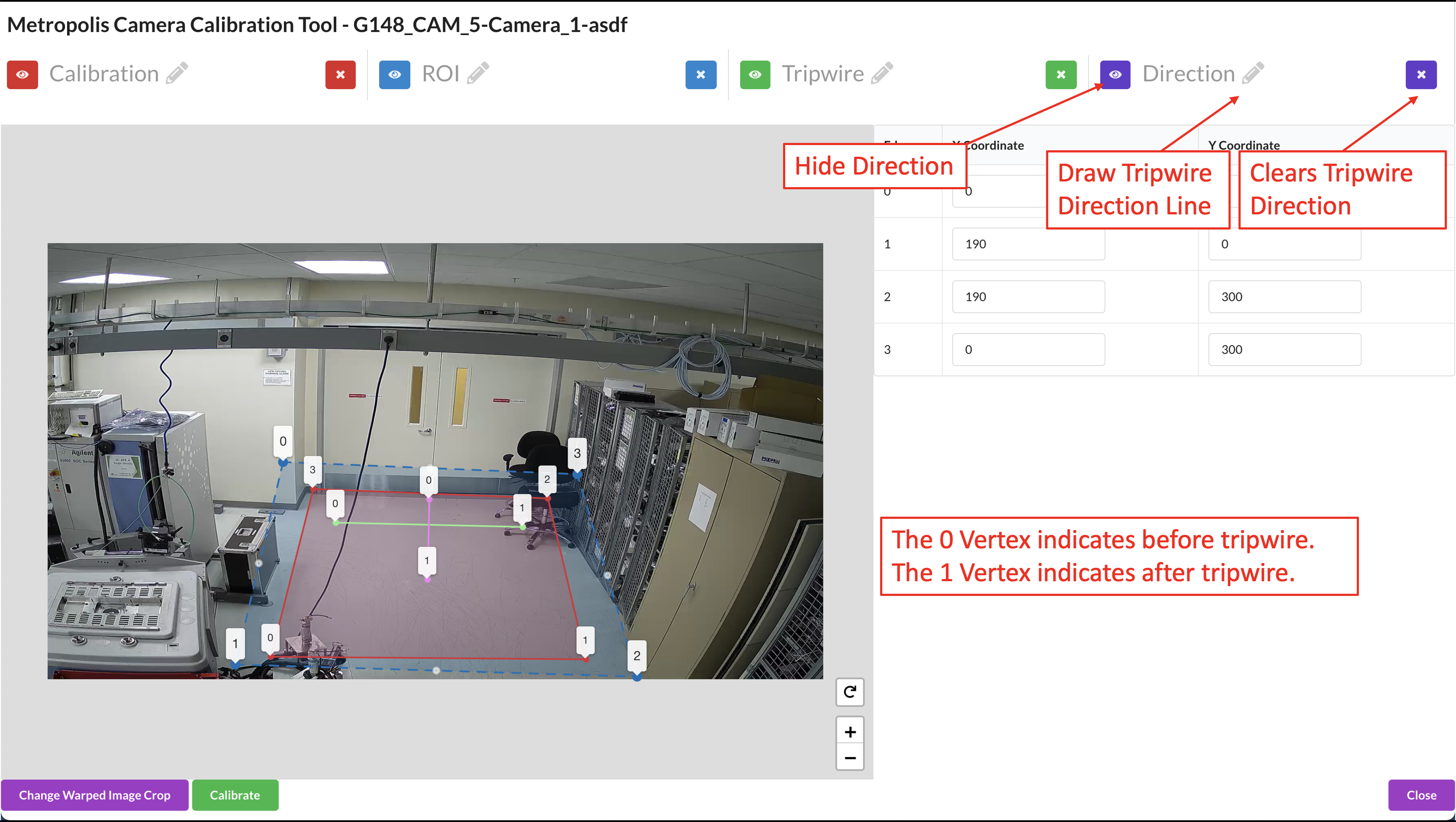
Draw the Tripwire Direction Wire.
When we are drawing, we want to draw line segments that correlate to the direction that objects will be entering the tripwire. This line must intersect the tripwire line. The 0 Point is be outside the zone, and the 1 point will be across the trip wire. Make sure that the polyline has only 2 points.
Validation
Validate the Images
Load the Validation Tool.
Draw a trajectory on the image, and validate that the projected polyline makes sense in the transformed image. Feel free to clear the image and try drawing as many trajectories as desired. Validate the Calibration when satisfied.
The ROI, Tripwire, and Direction lines will be projected onto the real world image. To adjust these lines, go back to the Project Type - Cartesian section.
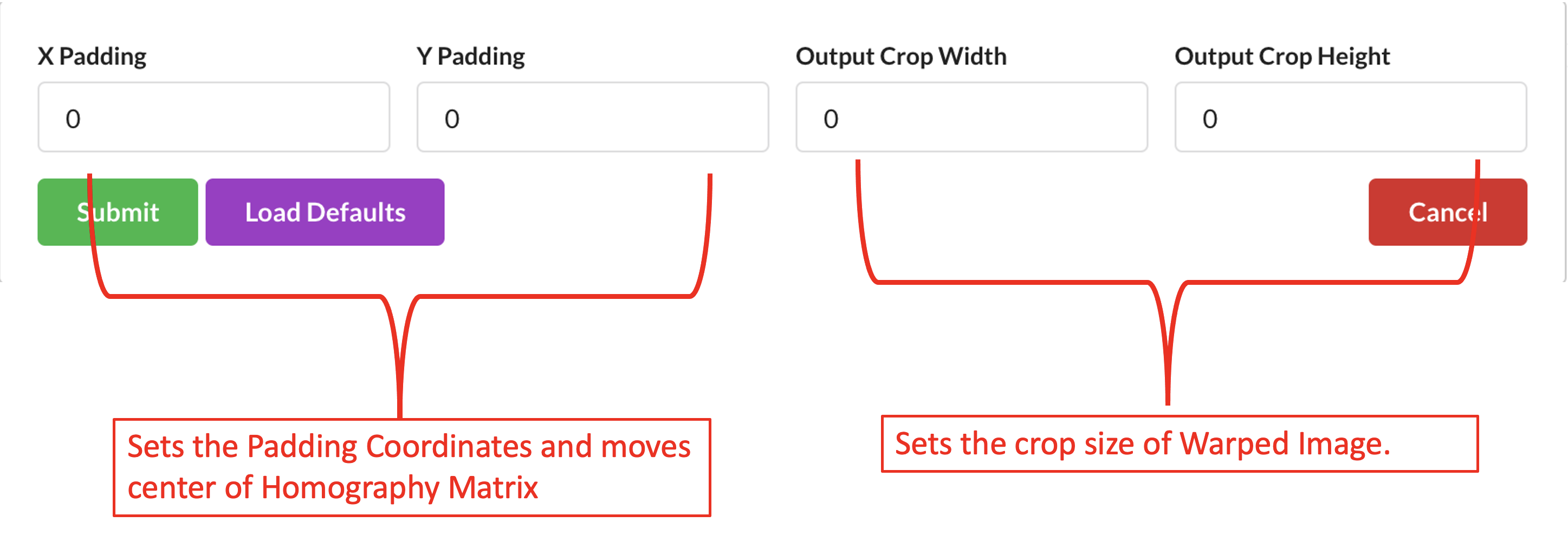
Generate Warped Image
We can adjust the warped image by padding pixels which moves the center of the crop taken, and adjusting the size of the crop.
ROI/Tripwire Setup
ROI/Tripwire Setup allows us to define ROIs, and tripwires for a sensor without any homography calibration. This is separate type of project type that is unrelated to multi-camera tracking or Approximate.
Generating the Artifacts
Draw the Region of Interest (ROI), which represents the area for which the calibration is intended to be valid. This does not necessarily have to be the sensor’s entire Field of View.
Use the toggle markers button for better visibility on the exact location of a point, or to hide the specified polygon or polyline.
Adding Tripwires/Direction
In calibration, we are able to add tripwires to enable counting.
Draw the tripwire
Draw a line segment that defines the region where we want to detect if objects have crossed. Make sure that the polyline has only 2 points. When we are drawing, we want to draw line segments that correlate to the direction that objects will be entering the tripwire. This line must intersect the tripwire line. The 0 Point is be outside the zone, and the 1 point will be across the trip wire. Make sure that the polyline has only 2 points as shown in the above image.
Export Artifacts
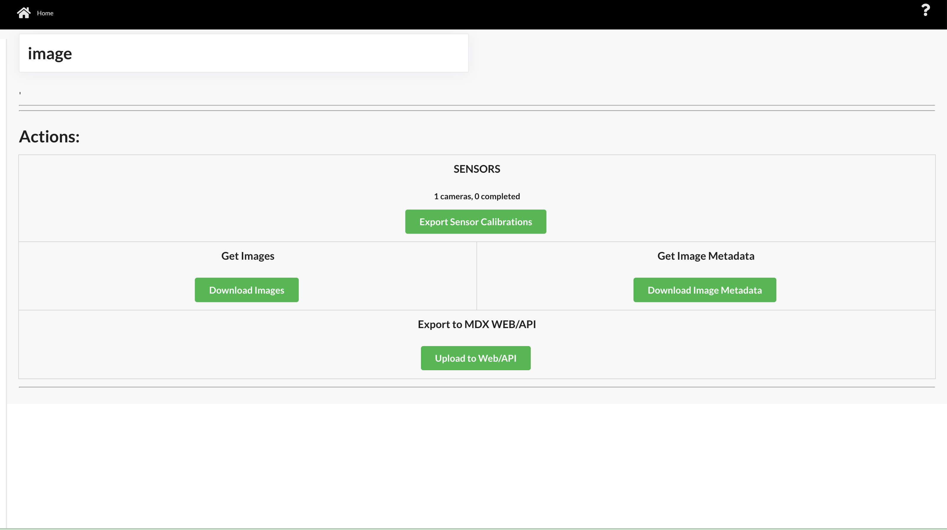
Camera Calibration
Click Export Camera Calibration to generate the calibration.json. It will include all validated cameras in your project. The file will download to the Downloads folder on the user’s computer. If you must, you can rename, add, or remove the places for each sensor. You can use a common text editor to edit them.
Image Metadata
Click Export Image Metadata to generate the imageMetadata.json and the images, which includes all the cameras and the associated details needed for the Metropolis web-API. The file will download to the Downloads folder on the user’s computer.
Images
Click Export Images to generate the images, which includes all the cameras and the associated details needed for the Metropolis Web API. The file will download to the Downloads folder on the user’s computer.
Consume Artifacts
To consume the calibration.json and other Calibration Toolkit artifacts, one way is to use the Analytics & Tracking Web API /config/upload-file/calibration endpoint.
It inserts the config file into Web API. For Behavior Analytics, these artifacts are passed via command-line to transforming image coordinates to cartesian coordinates as well.
For more information on consuming the camera calibration see Analytics and Tracking API and Behavior Analytics.
Customization
To help understand more and potentially customize the toolkit, the source code is provided at metropolis-apps-standalone-deployment/modules/camera-calibration-toolkit/ directory.