Key Technologies
This document examines key technologies used in constructing LinkX cables and transceivers for 100G-PAM4, 50G-PAM4, and 25G-NRZ -modulation based interconnects used to create 800G, 400G, 200G, 100G and 25Gb/s aggregate data rates. The following technologies are used in various combinations to create various cables and transceivers with different modulation rates, copper wires, connector shells, protocols, transceivers, optical connectors, and fibers.
Modulation rates
Protocol support for InfiniBand and Ethernet
Connector cages and plugs
Optical connectors
Optical fibers
Straight and splitter fiber crossover cables
Optical patch panels
Note: Aggregate rates can be created by several different combinations of technologies, e.g.,
400Gb/s = 4x100G-PAM4 or 8x50G-PAM4
200Gb/s = 2x100G-PAM4, 4x50G-PAM4, 8x25G-NRZ
100Gb/s = 1x100G-PAM4, 2x50G-PAM4 or 4x25G-NRZ
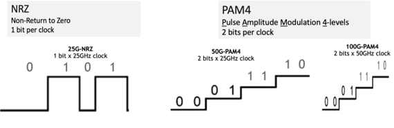
High-speed digital signaling uses several types of voltage modulation. Varying electrical voltages create digital pulses that vary in voltage amplitude or intensity. Modern data centers typically use NRZ for slower speeds and PAM4 for higher speeds.
NRZ Modulation
Early years of digital 1,0 signaling, a digital zero was inserted between every data bit so the receiver clock could synchronize on the data signal. This was called “Return-to-Zero” modulation. Later, as electronics became faster, the inserted zero was eliminated and the pulse synchronized on the edges of the data signals. This became known as “Non-Return-to-Zero” or NRZ. NRZ became the industry standard for 1G, 10G, and 25Gb/s and used for 1G, 10G, 25G, 40G, 100G aggregate data rates. Continuing to 50G became a problem as the electrical wires turned into radio antennae’s at high frequencies and caused the signal energy to be lost, which dramatically increased costs to contain the signals on circuit boards and wires.
PAM4 Modulation
Industry standards groups created a new modulation scheme that sent two data signals with a single clock pulse by varying the voltage intensity levels to four levels instead of two with NRZ. The four levels created two data bits per clock pulse or {00, 01} and {10, 11} visualized as two 1,0 data bits stacked on top of each other. This became known as Pulse Amplitude Modulation to 4-levels or PAM4.
50G-PAM4 kept the 25GHz slower clock speed of NRZ with two data bits stacked which enabled maintaining low costs. Later, faster electronics enabled using 50GHz clock with two data bits for 100G-PAM4. Soon, the industry will have 100GHz clocks and two data bits for 200G-PAM4.
100G-PAM4 modulation is used for 400Gb/s NDR InfiniBand and Spectrum-4 400Gb/s Ethernet systems:
800Gb/s = 8-channels 100G-PAM4
400Gb/s = 4-channels 100G-PAM4
200Gb/s = 2-channels 100G-PAM4
50G-PAM4 is used for 400G and 200G Spectrum-2/Spectrum-3 Ethernet and HDR InfiniBand:
400Gb/s = 8x50G-PAM4 used with QSFP-DD devices for Spectrum-3 Ethernet only systems
200Gb/s = 4x50G-PAM4 for 200GbE and HDR InfiniBand
25G-NRZ is used for 25G/100G Spectrum/Spectrum-2 Ethernet systems and 100Gb/s EDR InfiniBand:
100Gb/s = 4x25G-NRZ
50Gb/s = 2x25G-NRZ
25Gb/s = 1x25G-NRZ
Four-level signal modulation for 100G-PAM4 and 50G-PAM4 vs. two levels for 25G-NRZ
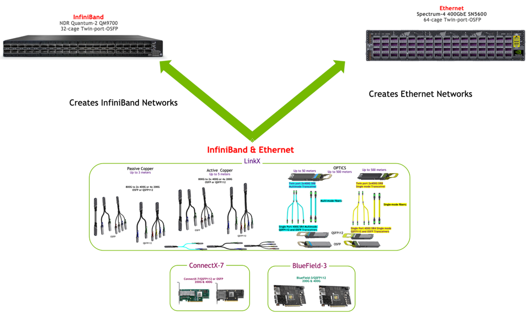
NVIDIA is the only provider of both InfiniBand and Ethernet networking. As the electrical and optical physics are the same for both protocols, NVIDIA combines the protocol support in the firmware coding of its network adapters, DPUs, cables and transceivers. The protocol is automatically enabled by the switch that the cables and transceivers are inserted into as the switches have specific Ethernet or InfiniBand protocols.
This feature is unique to NVIDIA and enables customers to better utilize adapter and interconnect set ups and for migrating systems and combining protocols based on different computing needs. One set of cables and transceivers and adapters can serve two protocols by simply changing the switches they are connected to. For example, DGX-H100 8 GPU systems may use InfiniBand for GPU-to-GPU networking and both InfiniBand and Ethernet for storage networking and other cluster communications links. The dual protocol capability is available with the 100G-PAM4 series, but fragments for the older 50G-PAM4 and 25G-NRZ devices as some devices are InfiniBand- or Ethernet-specific.
The 100G-PAM4 LinkX cables and transceivers, ConnectX-7 adapters, and BlueField-3 DPUs all support both InfiniBand and Ethernet protocols in the same device and use the same part numbers. The protocol of the network adapters and interconnects combination is determined when inserted into a Quantum-2 NDR InfiniBand or Spectrum-4 Ethernet switch.
However, this dual protocol capability is fragmented for 400GbE, 200GbE, HDR and 100GbE, EDR.
400GbE QSFP-DD switches based on 8x50G-PAM4 are Ethernet only, as InfiniBand does not use the QSFP-DD form-factor.
200Gb/s cables and transceivers based on 4x50G-PAM4 are mostly dual protocol with a few specific parts unique to Ethernet or InfiniBand, as InfiniBand requires a much lower bit error rating than Ethernet which increases testing costs.
100Gb/s cables and transceivers based on 4x25G-NRZ are a mix of combination and specific protocol parts. InfiniBand EDR is only 100Gb/s. SFP28 is not used for InfiniBand.
One dual-protocol LinkX cable, transceiver, ConnectX-7, and/or BlueField-3 DPU adapter assembly for various switch protocols