Hardware Installation
Installation and initialization of ConnectX-5 adapter cards for OCP Spec 3.0 require attention to the mechanical attributes, power specifications, and precautions for electronic equipment.
Safety Warnings
InfoSafety warnings are provided here in the English language. For safety warnings in other languages, refer to the Adapter Installation Safety Instructions.
Note that not all warnings are relevant to all models.

General Installation Instructions
Read all installation instructions before connecting the equipment to the power source.

Jewelry Removal Warning
Before you install or remove equipment that is connected to power lines, remove jewelry such as bracelets, necklaces, rings, watches, and so on. Metal objects heat up when connected to power and ground and can meltdown, causing serious burns and/or welding the metal object to the terminals.
Over-temperature
This equipment should not be operated in an area with an ambient temperature exceeding the maximum recommended: 55°C (131°F). An airflow of 200LFM at this maximum ambient temperature is required for HCA cards and NICs. To guarantee proper airflow, allow at least 8cm (3 inches) of clearance around the ventilation openings.
During Lightning - Electrical Hazard
During periods of lightning activity, do not work on the equipment or connect or disconnect cables.
Copper Cable Connecting/Disconnecting
Some copper cables are heavy and not flexible, as such, they should be carefully attached to or detached from the connectors. Refer to the cable manufacturer for special warnings and instructions.
Equipment Installation
This equipment should be installed, replaced, or serviced only by trained and qualified personnel.
Equipment Disposal
The disposal of this equipment should be in accordance to all national laws and regulations.
Local and National Electrical Codes
This equipment should be installed in compliance with local and national electrical codes.

Hazardous Radiation Exposure
Caution – Use of controls or adjustment or performance of procedures other than those specified herein may result in hazardous radiation exposure.For products with optical ports.
CLASS 1 LASER PRODUCT and reference to the most recent laser standards:
IEC 60 825-1:1993 + A1:1997 + A2:2001 and EN 60825-1:1994+A1:1996+ A2:20
Installation Procedure Overview
The installation procedure of ConnectX-5 adapter cards for OCP Spec 3.0 involves the following steps:
Step
Procedure
Direct Link
General Installation Instructions
Read all installation instructions before connecting the equipment to the power source.
Jewelry Removal Warning
Before you install or remove equipment that is connected to power lines, remove jewelry such as bracelets, necklaces, rings, watches, and so on. Metal objects heat up when connected to power and ground and can meltdown, causing serious burns and/or welding the metal object to the terminals.
Over-temperature
This equipment should not be operated in an area with an ambient temperature exceeding the maximum recommended: 55°C (131°F). An airflow of 200LFM at this maximum ambient temperature is required for HCA cards and NICs. To guarantee proper airflow, allow at least 8cm (3 inches) of clearance around the ventilation openings.
During Lightning - Electrical Hazard
During periods of lightning activity, do not work on the equipment or connect or disconnect cables.
Copper Cable Connecting/Disconnecting
Some copper cables are heavy and not flexible, as such, they should be carefully attached to or detached from the connectors. Refer to the cable manufacturer for special warnings and instructions.
Equipment Installation
This equipment should be installed, replaced, or serviced only by trained and qualified personnel.
Equipment Disposal
The disposal of this equipment should be in accordance to all national laws and regulations.
Local and National Electrical Codes
This equipment should be installed in compliance with local and national electrical codes.
Hazardous Radiation Exposure
Caution – Use of controls or adjustment or performance of procedures other than those specified herein may result in hazardous radiation exposure.For products with optical ports.
CLASS 1 LASER PRODUCT and reference to the most recent laser standards:
IEC 60 825-1:1993 + A1:1997 + A2:2001 and EN 60825-1:1994+A1:1996+ A2:20
1
Check the system’s hardware and software requirements.
Refer to System Requirements
2
Pay attention to the airflow consideration within the host system
Refer to Airflow Requirements
3
Follow the safety precautions
Refer to Safety Precautions
4
Follow the pre-installation checklist
Refer to Pre-Installation Checklist
5
(Optional) Replace the assembled OCP 3.0 bracket with the desired form factor bracket
6
Install ConnectX-5 adapter card in the system
according to the retention mechanism on the card
Refer to Thumbscrew (Pull-tab) Cards
Refer to Internal Lock Cards
7
Connect cables or modules to the card
Refer to Cables and Modules
8
Identify ConnectX-5 adapter card in the system
Refer to Identify the Card in Your System

System Requirements
WarningUnless otherwise specified, NVIDIA products are designed to work in an environmentally controlled data center with low levels of gaseous and dust (particulate) contamination.
The operating environment should meet severity level G1 as per ISA 71.04 for gaseous contamination and ISO 14644-1 class 8 for cleanliness level.
Hardware Requirements
WarningFor proper operation and performance, please make sure to use a PCIe slot with a corresponding bus width and that can supply sufficient power to your card. Refer to the Specifications section of the manual for more power requirements.
A system with a PCI Express x16 slot for OCP spec 3.0 is required for installing the card.
Airflow Requirements
ConnectX-5 adapter cards are offered with two airflow patterns: from the heatsink to the network ports, and vice versa, as shown below.
Please refer to the "Specifications" chapter for airflow numbers for each specific card model.
WarningAll cards in the system should be planned with the same airflow direction.
Step
Procedure
Direct Link
Heatsink-to-port Airflow Direction
Port-to-heatsink Airflow Direction
General Installation Instructions
Read all installation instructions before connecting the equipment to the power source.
Jewelry Removal Warning
Before you install or remove equipment that is connected to power lines, remove jewelry such as bracelets, necklaces, rings, watches, and so on. Metal objects heat up when connected to power and ground and can meltdown, causing serious burns and/or welding the metal object to the terminals.
Over-temperature
This equipment should not be operated in an area with an ambient temperature exceeding the maximum recommended: 55°C (131°F). An airflow of 200LFM at this maximum ambient temperature is required for HCA cards and NICs. To guarantee proper airflow, allow at least 8cm (3 inches) of clearance around the ventilation openings.
During Lightning - Electrical Hazard
During periods of lightning activity, do not work on the equipment or connect or disconnect cables.
Copper Cable Connecting/Disconnecting
Some copper cables are heavy and not flexible, as such, they should be carefully attached to or detached from the connectors. Refer to the cable manufacturer for special warnings and instructions.
Equipment Installation
This equipment should be installed, replaced, or serviced only by trained and qualified personnel.
Equipment Disposal
The disposal of this equipment should be in accordance to all national laws and regulations.
Local and National Electrical Codes
This equipment should be installed in compliance with local and national electrical codes.
Hazardous Radiation Exposure
Caution – Use of controls or adjustment or performance of procedures other than those specified herein may result in hazardous radiation exposure.For products with optical ports.
CLASS 1 LASER PRODUCT and reference to the most recent laser standards:
IEC 60 825-1:1993 + A1:1997 + A2:2001 and EN 60825-1:1994+A1:1996+ A2:20
1
Check the system’s hardware and software requirements.
Refer to System Requirements
2
Pay attention to the airflow consideration within the host system
Refer to Airflow Requirements
3
Follow the safety precautions
Refer to Safety Precautions
4
Follow the pre-installation checklist
Refer to Pre-Installation Checklist
5
(Optional) Replace the assembled OCP 3.0 bracket with the desired form factor bracket
6
Install ConnectX-5 adapter card in the system
according to the retention mechanism on the card
Refer to Thumbscrew (Pull-tab) Cards
Refer to Internal Lock Cards
7
Connect cables or modules to the card
Refer to Cables and Modules
8
Identify ConnectX-5 adapter card in the system
Refer to Identify the Card in Your System


Software Requirements
See Operating Systems/Distributions section under the Introduction section.
Software Stacks - NVIDIA OpenFabric software package MLNX_OFED for Linux, WinOF-2 for Windows, and VMware. See the Driver Installation section.
Safety Precautions
WarningThe adapter is being installed in a system that operates with voltages that can be lethal. Before opening the case of the system, observe the following precautions to avoid injury and prevent damage to system components.
Remove any metallic objects from your hands and wrists.
Make sure to use only insulated tools.
Verify that the system is powered off and is unplugged.
It is strongly recommended to use an ESD strap or other antistatic devices.
Remove any metallic objects from your hands and wrists.
Make sure to use only insulated tools.
Verify that the system is powered off and is unplugged.
It is strongly recommended to use an ESD strap or other antistatic devices.
Pre-Installation Checklist
Unpack the ConnectX-5 adapter card.
Unpack and remove the ConnectX-5 card. Check the parts for visible damage that may have occurred during shipping. Please note that the cards must be placed on an antistatic surface.WarningPlease note that if the card is removed hastily from the antistatic bag, the plastic ziplock may harm the EMI fingers on the networking connector. Carefully remove the card from the antistatic bag to avoid damaging the EMI fingers.
Shut down your system if active:
Turn off the power to the system, and disconnect the power cord. Refer to the system documentation for instructions. Before you install the ConnectX-5 card, make sure that the system is disconnected from power.
OCP 3.0 Bracket Replacement Instructions
The OCP 3.0 adapter card is shipped assembled either with a thumbscrew (pull-tab) bracket, an internal-lock bracket, or an ejector-latch bracket. If this form factor is suitable for your requirements, you can skip the remainder of this section and move to Installation Instructions. If you need to replace the assembled OCP 3.0 bracket with a different form-factor bracket, please follow the instructions in this section.
WarningDue to risk of damaging the EMI gasket, it is not recommended to replace the bracket more than three times.
To replace the bracket you will need the following parts:
The new bracket of the desired form factor.
The screws supplied with the new bracket kit.
The required torx tool type as specified in the instructions.
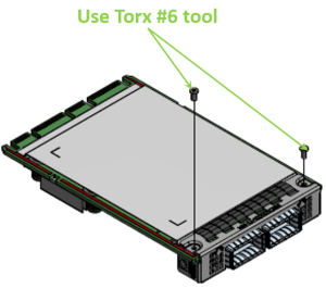
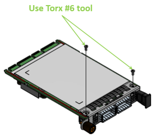
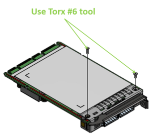
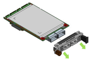
Removing the Existing Bracket
Using the torx tool type listed in the below table, remove the screws according to the instructions per OCP 3.0 bracket type.
Step
Procedure
Direct Link
Heatsink-to-port Airflow Direction
Port-to-heatsink Airflow Direction
Internal Lock Bracket
Pull-tab (Thumbscrew) Bracket
Ejector-Latch Bracket
General Installation Instructions
Read all installation instructions before connecting the equipment to the power source.
Jewelry Removal Warning
Before you install or remove equipment that is connected to power lines, remove jewelry such as bracelets, necklaces, rings, watches, and so on. Metal objects heat up when connected to power and ground and can meltdown, causing serious burns and/or welding the metal object to the terminals.
Over-temperature
This equipment should not be operated in an area with an ambient temperature exceeding the maximum recommended: 55°C (131°F). An airflow of 200LFM at this maximum ambient temperature is required for HCA cards and NICs. To guarantee proper airflow, allow at least 8cm (3 inches) of clearance around the ventilation openings.
During Lightning - Electrical Hazard
During periods of lightning activity, do not work on the equipment or connect or disconnect cables.
Copper Cable Connecting/Disconnecting
Some copper cables are heavy and not flexible, as such, they should be carefully attached to or detached from the connectors. Refer to the cable manufacturer for special warnings and instructions.
Equipment Installation
This equipment should be installed, replaced, or serviced only by trained and qualified personnel.
Equipment Disposal
The disposal of this equipment should be in accordance to all national laws and regulations.
Local and National Electrical Codes
This equipment should be installed in compliance with local and national electrical codes.
Hazardous Radiation Exposure
Caution – Use of controls or adjustment or performance of procedures other than those specified herein may result in hazardous radiation exposure.For products with optical ports.
CLASS 1 LASER PRODUCT and reference to the most recent laser standards:
IEC 60 825-1:1993 + A1:1997 + A2:2001 and EN 60825-1:1994+A1:1996+ A2:20
1
Check the system’s hardware and software requirements.
Refer to System Requirements
2
Pay attention to the airflow consideration within the host system
Refer to Airflow Requirements
3
Follow the safety precautions
Refer to Safety Precautions
4
Follow the pre-installation checklist
Refer to Pre-Installation Checklist
5
(Optional) Replace the assembled OCP 3.0 bracket with the desired form factor bracket
6
Install ConnectX-5 adapter card in the system
according to the retention mechanism on the card
Refer to Thumbscrew (Pull-tab) Cards
Refer to Internal Lock Cards
7
Connect cables or modules to the card
Refer to Cables and Modules
8
Identify ConnectX-5 adapter card in the system
Refer to Identify the Card in Your System
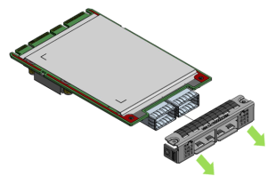
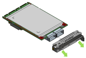
Gently separate the bracket from the OCP 3.0 card.
Step
Procedure
Direct Link
Heatsink-to-port Airflow Direction
Port-to-heatsink Airflow Direction
Internal Lock Bracket
Pull-tab (Thumbscrew) Bracket
Ejector-Latch Bracket
Internal Lock Bracket
Pull-tab Bracket
Ejector-Latch Bracket
General Installation Instructions
Read all installation instructions before connecting the equipment to the power source.
Jewelry Removal Warning
Before you install or remove equipment that is connected to power lines, remove jewelry such as bracelets, necklaces, rings, watches, and so on. Metal objects heat up when connected to power and ground and can meltdown, causing serious burns and/or welding the metal object to the terminals.
Over-temperature
This equipment should not be operated in an area with an ambient temperature exceeding the maximum recommended: 55°C (131°F). An airflow of 200LFM at this maximum ambient temperature is required for HCA cards and NICs. To guarantee proper airflow, allow at least 8cm (3 inches) of clearance around the ventilation openings.
During Lightning - Electrical Hazard
During periods of lightning activity, do not work on the equipment or connect or disconnect cables.
Copper Cable Connecting/Disconnecting
Some copper cables are heavy and not flexible, as such, they should be carefully attached to or detached from the connectors. Refer to the cable manufacturer for special warnings and instructions.
Equipment Installation
This equipment should be installed, replaced, or serviced only by trained and qualified personnel.
Equipment Disposal
The disposal of this equipment should be in accordance to all national laws and regulations.
Local and National Electrical Codes
This equipment should be installed in compliance with local and national electrical codes.
Hazardous Radiation Exposure
Caution – Use of controls or adjustment or performance of procedures other than those specified herein may result in hazardous radiation exposure.For products with optical ports.
CLASS 1 LASER PRODUCT and reference to the most recent laser standards:
IEC 60 825-1:1993 + A1:1997 + A2:2001 and EN 60825-1:1994+A1:1996+ A2:20
1
Check the system’s hardware and software requirements.
Refer to System Requirements
2
Pay attention to the airflow consideration within the host system
Refer to Airflow Requirements
3
Follow the safety precautions
Refer to Safety Precautions
4
Follow the pre-installation checklist
Refer to Pre-Installation Checklist
5
(Optional) Replace the assembled OCP 3.0 bracket with the desired form factor bracket
6
Install ConnectX-5 adapter card in the system
according to the retention mechanism on the card
Refer to Thumbscrew (Pull-tab) Cards
Refer to Internal Lock Cards
7
Connect cables or modules to the card
Refer to Cables and Modules
8
Identify ConnectX-5 adapter card in the system
Refer to Identify the Card in Your System
 Warning
Be careful not to put stress on the LEDs on the adapter card.
Save the two screws.
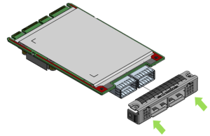
Installing the New Bracket
Assemble the new bracket onto the card.
Step
Procedure
Direct Link
Heatsink-to-port Airflow Direction
Port-to-heatsink Airflow Direction
Internal Lock Bracket
Pull-tab (Thumbscrew) Bracket
Ejector-Latch Bracket
Internal Lock Bracket
Pull-tab Bracket
Ejector-Latch Bracket
Internal Lock Bracket
Pull-tab Bracket
Ejector-Latch Bracket
General Installation Instructions
Read all installation instructions before connecting the equipment to the power source.
Jewelry Removal Warning
Before you install or remove equipment that is connected to power lines, remove jewelry such as bracelets, necklaces, rings, watches, and so on. Metal objects heat up when connected to power and ground and can meltdown, causing serious burns and/or welding the metal object to the terminals.
Over-temperature
This equipment should not be operated in an area with an ambient temperature exceeding the maximum recommended: 55°C (131°F). An airflow of 200LFM at this maximum ambient temperature is required for HCA cards and NICs. To guarantee proper airflow, allow at least 8cm (3 inches) of clearance around the ventilation openings.
During Lightning - Electrical Hazard
During periods of lightning activity, do not work on the equipment or connect or disconnect cables.
Copper Cable Connecting/Disconnecting
Some copper cables are heavy and not flexible, as such, they should be carefully attached to or detached from the connectors. Refer to the cable manufacturer for special warnings and instructions.
Equipment Installation
This equipment should be installed, replaced, or serviced only by trained and qualified personnel.
Equipment Disposal
The disposal of this equipment should be in accordance to all national laws and regulations.
Local and National Electrical Codes
This equipment should be installed in compliance with local and national electrical codes.
Hazardous Radiation Exposure
Caution – Use of controls or adjustment or performance of procedures other than those specified herein may result in hazardous radiation exposure.For products with optical ports.
CLASS 1 LASER PRODUCT and reference to the most recent laser standards:
IEC 60 825-1:1993 + A1:1997 + A2:2001 and EN 60825-1:1994+A1:1996+ A2:20
1
Check the system’s hardware and software requirements.
Refer to System Requirements
2
Pay attention to the airflow consideration within the host system
Refer to Airflow Requirements
3
Follow the safety precautions
Refer to Safety Precautions
4
Follow the pre-installation checklist
Refer to Pre-Installation Checklist
5
(Optional) Replace the assembled OCP 3.0 bracket with the desired form factor bracket
6
Install ConnectX-5 adapter card in the system
according to the retention mechanism on the card
Refer to Thumbscrew (Pull-tab) Cards
Refer to Internal Lock Cards
7
Connect cables or modules to the card
Refer to Cables and Modules
8
Identify ConnectX-5 adapter card in the system
Refer to Identify the Card in Your System
 Warning
Do not force the bracket onto the adapter card.
Ensure that the insulator's front edge is beneath the bracket, as shown in the below figure.
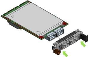
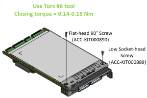
Screw on the OCP 3.0 bracket with the supplied screws that came with the new bracket kit. Use the specified torx tool type and apply the specified torque on the screws per bracket form factor.
Step
Procedure
Direct Link
Heatsink-to-port Airflow Direction
Port-to-heatsink Airflow Direction
Internal Lock Bracket
Pull-tab (Thumbscrew) Bracket
Ejector-Latch Bracket
Internal Lock Bracket
Pull-tab Bracket
Ejector-Latch Bracket
Internal Lock Bracket
Pull-tab Bracket
Ejector-Latch Bracket
Internal Lock Bracket
Pull-tab Bracket
Ejector-Latch Bracket
General Installation Instructions
Read all installation instructions before connecting the equipment to the power source.
Jewelry Removal Warning
Before you install or remove equipment that is connected to power lines, remove jewelry such as bracelets, necklaces, rings, watches, and so on. Metal objects heat up when connected to power and ground and can meltdown, causing serious burns and/or welding the metal object to the terminals.
Over-temperature
This equipment should not be operated in an area with an ambient temperature exceeding the maximum recommended: 55°C (131°F). An airflow of 200LFM at this maximum ambient temperature is required for HCA cards and NICs. To guarantee proper airflow, allow at least 8cm (3 inches) of clearance around the ventilation openings.
During Lightning - Electrical Hazard
During periods of lightning activity, do not work on the equipment or connect or disconnect cables.
Copper Cable Connecting/Disconnecting
Some copper cables are heavy and not flexible, as such, they should be carefully attached to or detached from the connectors. Refer to the cable manufacturer for special warnings and instructions.
Equipment Installation
This equipment should be installed, replaced, or serviced only by trained and qualified personnel.
Equipment Disposal
The disposal of this equipment should be in accordance to all national laws and regulations.
Local and National Electrical Codes
This equipment should be installed in compliance with local and national electrical codes.
Hazardous Radiation Exposure
Caution – Use of controls or adjustment or performance of procedures other than those specified herein may result in hazardous radiation exposure.For products with optical ports.
CLASS 1 LASER PRODUCT and reference to the most recent laser standards:
IEC 60 825-1:1993 + A1:1997 + A2:2001 and EN 60825-1:1994+A1:1996+ A2:20
1
Check the system’s hardware and software requirements.
Refer to System Requirements
2
Pay attention to the airflow consideration within the host system
Refer to Airflow Requirements
3
Follow the safety precautions
Refer to Safety Precautions
4
Follow the pre-installation checklist
Refer to Pre-Installation Checklist
5
(Optional) Replace the assembled OCP 3.0 bracket with the desired form factor bracket
6
Install ConnectX-5 adapter card in the system
according to the retention mechanism on the card
Refer to Thumbscrew (Pull-tab) Cards
Refer to Internal Lock Cards
7
Connect cables or modules to the card
Refer to Cables and Modules
8
Identify ConnectX-5 adapter card in the system
Refer to Identify the Card in Your System
Note that one screw is flat-head 90° screw and the other is socket-head screw. Screw on the different types of screws as shown in the below illustration.
OCP 3.0 Adapter Card Installation Instructions
This section provides detailed instructions on how to install your adapter card in a system. The OCP 3.0 adapter card is shipped assembled either with an internal-lock, a pull-tab (thumbscrew), or an ejector-latch bracket. Follow the below instructions depending on the card you have purchased.
NoteThe following figures are for illustration purposes only.
Before installing the card, make sure that the system is off and the power cord is not connected to the server. Please follow proper electrical grounding procedures.
Open the system case.
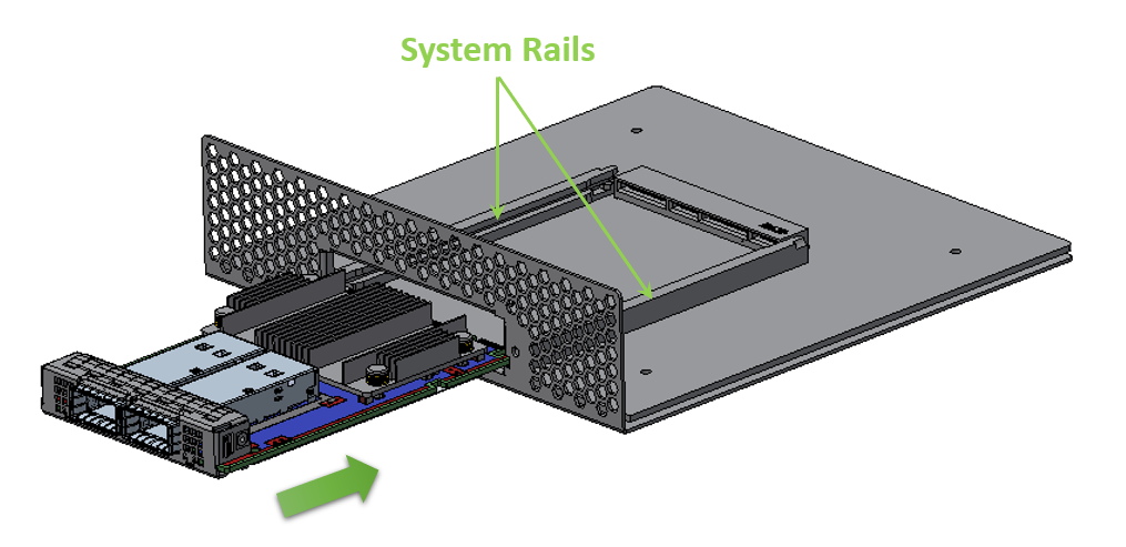
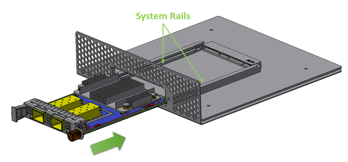
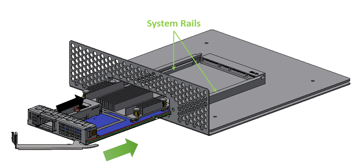
Align the card with the system rails.
Step
Procedure
Direct Link
Heatsink-to-port Airflow Direction
Port-to-heatsink Airflow Direction
Internal Lock Bracket
Pull-tab (Thumbscrew) Bracket
Ejector-Latch Bracket
Internal Lock Bracket
Pull-tab Bracket
Ejector-Latch Bracket
Internal Lock Bracket
Pull-tab Bracket
Ejector-Latch Bracket
Internal Lock Bracket
Pull-tab Bracket
Ejector-Latch Bracket
Internal Lock Bracket
Pull-tab (Thumbscrew) Bracket
Ejector-Latch Bracket
General Installation Instructions
Read all installation instructions before connecting the equipment to the power source.
Jewelry Removal Warning
Before you install or remove equipment that is connected to power lines, remove jewelry such as bracelets, necklaces, rings, watches, and so on. Metal objects heat up when connected to power and ground and can meltdown, causing serious burns and/or welding the metal object to the terminals.
Over-temperature
This equipment should not be operated in an area with an ambient temperature exceeding the maximum recommended: 55°C (131°F). An airflow of 200LFM at this maximum ambient temperature is required for HCA cards and NICs. To guarantee proper airflow, allow at least 8cm (3 inches) of clearance around the ventilation openings.
During Lightning - Electrical Hazard
During periods of lightning activity, do not work on the equipment or connect or disconnect cables.
Copper Cable Connecting/Disconnecting
Some copper cables are heavy and not flexible, as such, they should be carefully attached to or detached from the connectors. Refer to the cable manufacturer for special warnings and instructions.
Equipment Installation
This equipment should be installed, replaced, or serviced only by trained and qualified personnel.
Equipment Disposal
The disposal of this equipment should be in accordance to all national laws and regulations.
Local and National Electrical Codes
This equipment should be installed in compliance with local and national electrical codes.
Hazardous Radiation Exposure
Caution – Use of controls or adjustment or performance of procedures other than those specified herein may result in hazardous radiation exposure.For products with optical ports.
CLASS 1 LASER PRODUCT and reference to the most recent laser standards:
IEC 60 825-1:1993 + A1:1997 + A2:2001 and EN 60825-1:1994+A1:1996+ A2:20
1
Check the system’s hardware and software requirements.
Refer to System Requirements
2
Pay attention to the airflow consideration within the host system
Refer to Airflow Requirements
3
Follow the safety precautions
Refer to Safety Precautions
4
Follow the pre-installation checklist
Refer to Pre-Installation Checklist
5
(Optional) Replace the assembled OCP 3.0 bracket with the desired form factor bracket
6
Install ConnectX-5 adapter card in the system
according to the retention mechanism on the card
Refer to Thumbscrew (Pull-tab) Cards
Refer to Internal Lock Cards
7
Connect cables or modules to the card
Refer to Cables and Modules
8
Identify ConnectX-5 adapter card in the system
Refer to Identify the Card in Your System
Note that one screw is flat-head 90° screw and the other is socket-head screw. Screw on the different types of screws as shown in the below illustration.
Push the card until connectors are in a full mate.
Step
Procedure
Direct Link
Heatsink-to-port Airflow Direction
Port-to-heatsink Airflow Direction
Internal Lock Bracket
Pull-tab (Thumbscrew) Bracket
Ejector-Latch Bracket
Internal Lock Bracket
Pull-tab Bracket
Ejector-Latch Bracket
Internal Lock Bracket
Pull-tab Bracket
Ejector-Latch Bracket
Internal Lock Bracket
Pull-tab Bracket
Ejector-Latch Bracket
Internal Lock Bracket
Pull-tab (Thumbscrew) Bracket
Ejector-Latch Bracket
Internal Lock Bracket
Pull-tab (Thumbscrew) Bracket
Ejector-Latch Bracket
General Installation Instructions
Read all installation instructions before connecting the equipment to the power source.
Jewelry Removal Warning
Before you install or remove equipment that is connected to power lines, remove jewelry such as bracelets, necklaces, rings, watches, and so on. Metal objects heat up when connected to power and ground and can meltdown, causing serious burns and/or welding the metal object to the terminals.
Over-temperature
This equipment should not be operated in an area with an ambient temperature exceeding the maximum recommended: 55°C (131°F). An airflow of 200LFM at this maximum ambient temperature is required for HCA cards and NICs. To guarantee proper airflow, allow at least 8cm (3 inches) of clearance around the ventilation openings.
During Lightning - Electrical Hazard
During periods of lightning activity, do not work on the equipment or connect or disconnect cables.
Copper Cable Connecting/Disconnecting
Some copper cables are heavy and not flexible, as such, they should be carefully attached to or detached from the connectors. Refer to the cable manufacturer for special warnings and instructions.
Equipment Installation
This equipment should be installed, replaced, or serviced only by trained and qualified personnel.
Equipment Disposal
The disposal of this equipment should be in accordance to all national laws and regulations.
Local and National Electrical Codes
This equipment should be installed in compliance with local and national electrical codes.
Hazardous Radiation Exposure
Caution – Use of controls or adjustment or performance of procedures other than those specified herein may result in hazardous radiation exposure.For products with optical ports.
CLASS 1 LASER PRODUCT and reference to the most recent laser standards:
IEC 60 825-1:1993 + A1:1997 + A2:2001 and EN 60825-1:1994+A1:1996+ A2:20
1
Check the system’s hardware and software requirements.
Refer to System Requirements
2
Pay attention to the airflow consideration within the host system
Refer to Airflow Requirements
3
Follow the safety precautions
Refer to Safety Precautions
4
Follow the pre-installation checklist
Refer to Pre-Installation Checklist
5
(Optional) Replace the assembled OCP 3.0 bracket with the desired form factor bracket
6
Install ConnectX-5 adapter card in the system
according to the retention mechanism on the card
Refer to Thumbscrew (Pull-tab) Cards
Refer to Internal Lock Cards
7
Connect cables or modules to the card
Refer to Cables and Modules
8
Identify ConnectX-5 adapter card in the system
Refer to Identify the Card in Your System
Note that one screw is flat-head 90° screw and the other is socket-head screw. Screw on the different types of screws as shown in the below illustration.
Secure the card.
Step
Procedure
Direct Link
Heatsink-to-port Airflow Direction
Port-to-heatsink Airflow Direction
Internal Lock Bracket
Pull-tab (Thumbscrew) Bracket
Ejector-Latch Bracket
Internal Lock Bracket
Pull-tab Bracket
Ejector-Latch Bracket
Internal Lock Bracket
Pull-tab Bracket
Ejector-Latch Bracket
Internal Lock Bracket
Pull-tab Bracket
Ejector-Latch Bracket
Internal Lock Bracket
Pull-tab (Thumbscrew) Bracket
Ejector-Latch Bracket
Internal Lock Bracket
Pull-tab (Thumbscrew) Bracket
Ejector-Latch Bracket
Internal Lock Bracket
Pull-tab (Thumbscrew) Bracket
Ejector-Latch Bracket
General Installation Instructions
Read all installation instructions before connecting the equipment to the power source.
Jewelry Removal Warning
Before you install or remove equipment that is connected to power lines, remove jewelry such as bracelets, necklaces, rings, watches, and so on. Metal objects heat up when connected to power and ground and can meltdown, causing serious burns and/or welding the metal object to the terminals.
Over-temperature
This equipment should not be operated in an area with an ambient temperature exceeding the maximum recommended: 55°C (131°F). An airflow of 200LFM at this maximum ambient temperature is required for HCA cards and NICs. To guarantee proper airflow, allow at least 8cm (3 inches) of clearance around the ventilation openings.
During Lightning - Electrical Hazard
During periods of lightning activity, do not work on the equipment or connect or disconnect cables.
Copper Cable Connecting/Disconnecting
Some copper cables are heavy and not flexible, as such, they should be carefully attached to or detached from the connectors. Refer to the cable manufacturer for special warnings and instructions.
Equipment Installation
This equipment should be installed, replaced, or serviced only by trained and qualified personnel.
Equipment Disposal
The disposal of this equipment should be in accordance to all national laws and regulations.
Local and National Electrical Codes
This equipment should be installed in compliance with local and national electrical codes.
Hazardous Radiation Exposure
Caution – Use of controls or adjustment or performance of procedures other than those specified herein may result in hazardous radiation exposure.For products with optical ports.
CLASS 1 LASER PRODUCT and reference to the most recent laser standards:
IEC 60 825-1:1993 + A1:1997 + A2:2001 and EN 60825-1:1994+A1:1996+ A2:20
1
Check the system’s hardware and software requirements.
Refer to System Requirements
2
Pay attention to the airflow consideration within the host system
Refer to Airflow Requirements
3
Follow the safety precautions
Refer to Safety Precautions
4
Follow the pre-installation checklist
Refer to Pre-Installation Checklist
5
(Optional) Replace the assembled OCP 3.0 bracket with the desired form factor bracket
6
Install ConnectX-5 adapter card in the system
according to the retention mechanism on the card
Refer to Thumbscrew (Pull-tab) Cards
Refer to Internal Lock Cards
7
Connect cables or modules to the card
Refer to Cables and Modules
8
Identify ConnectX-5 adapter card in the system
Refer to Identify the Card in Your System
Note that one screw is flat-head 90° screw and the other is socket-head screw. Screw on the different types of screws as shown in the below illustration.
A clicking sound is heard once the connectors are in a full mate.
Turn the captive screw clockwise until firmly locked.
Close the ejector.
To uninstall the adapter card, see Uninstalling the Card.
Cables and Modules
Cable Installation
All cables can be inserted or removed with the unit powered on.
To insert a cable, press the connector into the port receptacle until the connector is firmly seated.
Support the weight of the cable before connecting the cable to the adapter card. Do this by using a cable holder or tying the cable to the rack.
Determine the correct orientation of the connector to the card before inserting the connector. Do not try and insert the connector upside down. This may damage the adapter card.
Insert the connector into the adapter card. Be careful to insert the connector straight into the cage. Do not apply any torque, up or down, to the connector cage in the adapter card.
Make sure that the connector locks in place.
NoteWhen installing cables make sure that the latches engage.
WarningAlways install and remove cables by pushing or pulling the cable and connector in a straight line with the card.
After inserting a cable into a port, the Yellow or Green LED0 indicator will light when the physical connection is established (that is, when the unit is powered on and a cable is plugged into the port with the other end of the connector plugged into a functioning port). See Adapter Card LED Operations.
After plugging in a cable, lock the connector using the latching mechanism particular to the cable vendor. When a logical connection is made, Green LED1 will light. When data is being transferred, Green LED1 will blink.
Care should be taken as not to impede the air exhaust flow through the ventilation holes. Use cable lengths which allow for routing horizontally around to the side of the chassis before bending upward or downward in the rack.
To remove a cable, disengage the locks and slowly pull the connector away from the port receptacle. LED indicator will turn off when the cable is unseated.
Identifying the Card in Your System
On Linux
Get the device location on the PCI bus by running lspci and locating lines with the string “Mellanox Technologies”:
lspci |grep -i Mellanox Network controller: Mellanox Technologies MT28800 Family [ConnectX-
5]On Windows
Open Device Manager on the server. Click Start => Run, and then enter devmgmt.msc.
Expand System Devices and locate your NVIDIA ConnectX-5 adapter card.
Right click the mouse on your adapter's row and select Properties to display the adapter card properties window.
Click the Details tab and select Hardware Ids (Windows 2012/R2/2016) from the Property pull-down menu.
PCI Device (Example)
In the Value display box, check the fields VEN and DEV (fields are separated by ‘&’). In the display example above, notice the sub-string “PCI\VEN_15B3&DEV_1003”: VEN is equal to 0x15B3 – this is the Vendor ID of NVIDIA; and DEV is equal to 1018 (for ConnectX-5) – this is a valid NVIDIA PCI Device ID.
NoteIf the PCI device does not have a NVIDIA adapter ID, return to Step 2 to check another device.
NoteThe list of NVIDIA PCI Device IDs can be found at the PCI ID repository.
Cards Extraction Instructions
Follow the below instructions depending on the card form-factor you have purchased.
Safety Precautions
The adapter is installed in a system that operates with voltages that can be lethal. Before uninstalling the adapter card, please observe the following precautions to avoid injury and prevent damage to system components.
Remove any metallic objects from your hands and wrists.
It is strongly recommended to use an ESD strap or other antistatic devices.
Turn off the system and disconnect the power cord from the server.
Instructions
NotePlease note that the following images are for illustration purposes only.
Verify that the system is powered off and unplugged.
Wait 30 seconds.
Unsecure the card.
Step
Procedure
Direct Link
Heatsink-to-port Airflow Direction
Port-to-heatsink Airflow Direction
Internal Lock Bracket
Pull-tab (Thumbscrew) Bracket
Ejector-Latch Bracket
Internal Lock Bracket
Pull-tab Bracket
Ejector-Latch Bracket
Internal Lock Bracket
Pull-tab Bracket
Ejector-Latch Bracket
Internal Lock Bracket
Pull-tab Bracket
Ejector-Latch Bracket
Internal Lock Bracket
Pull-tab (Thumbscrew) Bracket
Ejector-Latch Bracket
Internal Lock Bracket
Pull-tab (Thumbscrew) Bracket
Ejector-Latch Bracket
Internal Lock Bracket
Pull-tab (Thumbscrew) Bracket
Ejector-Latch Bracket
Internal Lock Bracket
Pull-tab (Thumbscrew) Bracket
Ejector-Latch Bracket
General Installation Instructions
Read all installation instructions before connecting the equipment to the power source.
Jewelry Removal Warning
Before you install or remove equipment that is connected to power lines, remove jewelry such as bracelets, necklaces, rings, watches, and so on. Metal objects heat up when connected to power and ground and can meltdown, causing serious burns and/or welding the metal object to the terminals.
Over-temperature
This equipment should not be operated in an area with an ambient temperature exceeding the maximum recommended: 55°C (131°F). An airflow of 200LFM at this maximum ambient temperature is required for HCA cards and NICs. To guarantee proper airflow, allow at least 8cm (3 inches) of clearance around the ventilation openings.
During Lightning - Electrical Hazard
During periods of lightning activity, do not work on the equipment or connect or disconnect cables.
Copper Cable Connecting/Disconnecting
Some copper cables are heavy and not flexible, as such, they should be carefully attached to or detached from the connectors. Refer to the cable manufacturer for special warnings and instructions.
Equipment Installation
This equipment should be installed, replaced, or serviced only by trained and qualified personnel.
Equipment Disposal
The disposal of this equipment should be in accordance to all national laws and regulations.
Local and National Electrical Codes
This equipment should be installed in compliance with local and national electrical codes.
Hazardous Radiation Exposure
Caution – Use of controls or adjustment or performance of procedures other than those specified herein may result in hazardous radiation exposure.For products with optical ports.
CLASS 1 LASER PRODUCT and reference to the most recent laser standards:
IEC 60 825-1:1993 + A1:1997 + A2:2001 and EN 60825-1:1994+A1:1996+ A2:20
1
Check the system’s hardware and software requirements.
Refer to System Requirements
2
Pay attention to the airflow consideration within the host system
Refer to Airflow Requirements
3
Follow the safety precautions
Refer to Safety Precautions
4
Follow the pre-installation checklist
Refer to Pre-Installation Checklist
5
(Optional) Replace the assembled OCP 3.0 bracket with the desired form factor bracket
6
Install ConnectX-5 adapter card in the system
according to the retention mechanism on the card
Refer to Thumbscrew (Pull-tab) Cards
Refer to Internal Lock Cards
7
Connect cables or modules to the card
Refer to Cables and Modules
8
Identify ConnectX-5 adapter card in the system
Refer to Identify the Card in Your System
Note that one screw is flat-head 90° screw and the other is socket-head screw. Screw on the different types of screws as shown in the below illustration.
A clicking sound is heard once the connectors are in a full mate.
Turn the captive screw clockwise until firmly locked.
Close the ejector.
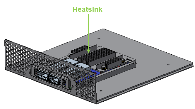
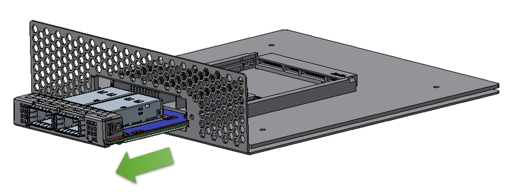
While holding the heatsink, gently push the card out of the server.
 Warning
Careful, the heatsink might be hot.
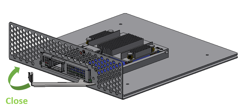
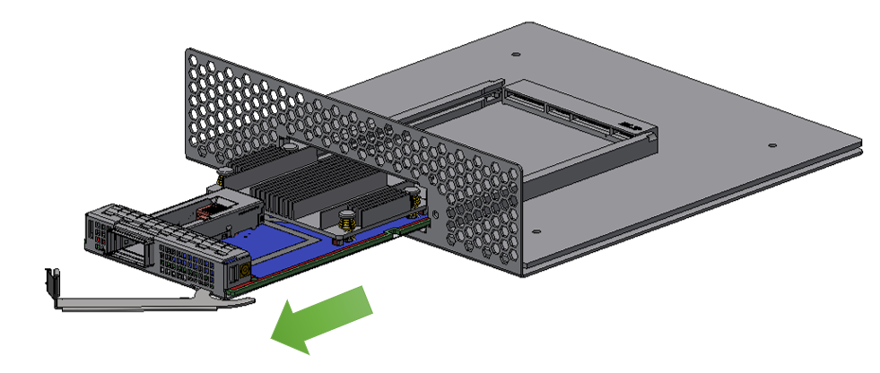
Rotate the captive screw counterclockwise.
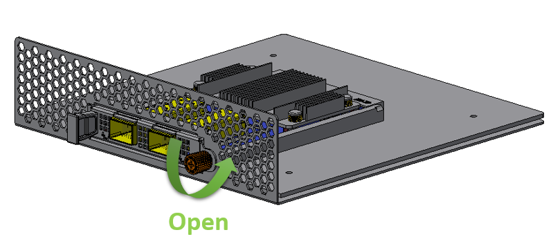
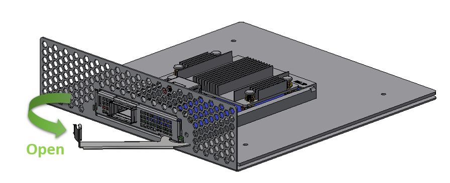
Open the ejector latch.
Gently pull out the adapter card.
Step
Procedure
Direct Link
Heatsink-to-port Airflow Direction
Port-to-heatsink Airflow Direction
Internal Lock Bracket
Pull-tab (Thumbscrew) Bracket
Ejector-Latch Bracket
Internal Lock Bracket
Pull-tab Bracket
Ejector-Latch Bracket
Internal Lock Bracket
Pull-tab Bracket
Ejector-Latch Bracket
Internal Lock Bracket
Pull-tab Bracket
Ejector-Latch Bracket
Internal Lock Bracket
Pull-tab (Thumbscrew) Bracket
Ejector-Latch Bracket
Internal Lock Bracket
Pull-tab (Thumbscrew) Bracket
Ejector-Latch Bracket
Internal Lock Bracket
Pull-tab (Thumbscrew) Bracket
Ejector-Latch Bracket
Internal Lock Bracket
Pull-tab (Thumbscrew) Bracket
Ejector-Latch Bracket
Internal Lock Bracket
Pull-tab (Thumbscrew) Bracket
Ejector-Latch Bracket
General Installation Instructions
Read all installation instructions before connecting the equipment to the power source.
Jewelry Removal Warning
Before you install or remove equipment that is connected to power lines, remove jewelry such as bracelets, necklaces, rings, watches, and so on. Metal objects heat up when connected to power and ground and can meltdown, causing serious burns and/or welding the metal object to the terminals.
Over-temperature
This equipment should not be operated in an area with an ambient temperature exceeding the maximum recommended: 55°C (131°F). An airflow of 200LFM at this maximum ambient temperature is required for HCA cards and NICs. To guarantee proper airflow, allow at least 8cm (3 inches) of clearance around the ventilation openings.
During Lightning - Electrical Hazard
During periods of lightning activity, do not work on the equipment or connect or disconnect cables.
Copper Cable Connecting/Disconnecting
Some copper cables are heavy and not flexible, as such, they should be carefully attached to or detached from the connectors. Refer to the cable manufacturer for special warnings and instructions.
Equipment Installation
This equipment should be installed, replaced, or serviced only by trained and qualified personnel.
Equipment Disposal
The disposal of this equipment should be in accordance to all national laws and regulations.
Local and National Electrical Codes
This equipment should be installed in compliance with local and national electrical codes.
Hazardous Radiation Exposure
Caution – Use of controls or adjustment or performance of procedures other than those specified herein may result in hazardous radiation exposure.For products with optical ports.
CLASS 1 LASER PRODUCT and reference to the most recent laser standards:
IEC 60 825-1:1993 + A1:1997 + A2:2001 and EN 60825-1:1994+A1:1996+ A2:20
1
Check the system’s hardware and software requirements.
Refer to System Requirements
2
Pay attention to the airflow consideration within the host system
Refer to Airflow Requirements
3
Follow the safety precautions
Refer to Safety Precautions
4
Follow the pre-installation checklist
Refer to Pre-Installation Checklist
5
(Optional) Replace the assembled OCP 3.0 bracket with the desired form factor bracket
6
Install ConnectX-5 adapter card in the system
according to the retention mechanism on the card
Refer to Thumbscrew (Pull-tab) Cards
Refer to Internal Lock Cards
7
Connect cables or modules to the card
Refer to Cables and Modules
8
Identify ConnectX-5 adapter card in the system
Refer to Identify the Card in Your System
Note that one screw is flat-head 90° screw and the other is socket-head screw. Screw on the different types of screws as shown in the below illustration.
A clicking sound is heard once the connectors are in a full mate.
Turn the captive screw clockwise until firmly locked.
Close the ejector.
While holding the heatsink, gently push the card out of the server.
WarningCareful, the heatsink might be hot.
Rotate the captive screw counterclockwise.
Open the ejector latch.
Gently pull out the adapter card from the server.
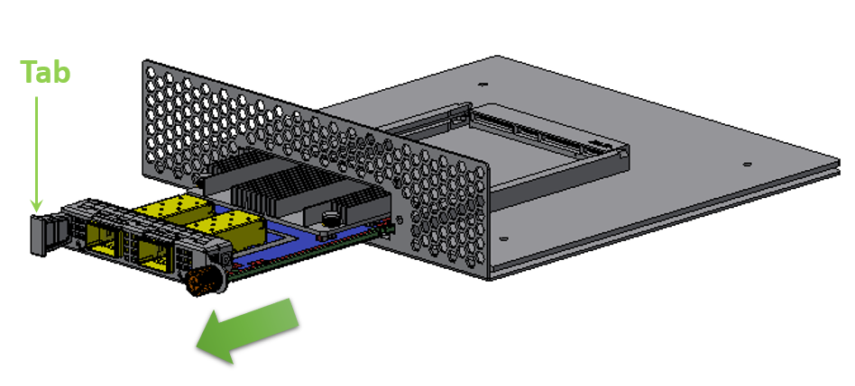
While holding the tab, pull out the adapter card.
Open the ejector latch.
Safety warnings are provided here in the English language. For safety warnings in other languages, refer to the Adapter Installation Safety Instructions.
Note that not all warnings are relevant to all models.

| General Installation Instructions |

| Jewelry Removal Warning |
|
| Over-temperature |
|
| During Lightning - Electrical Hazard |
|
| Copper Cable Connecting/Disconnecting |
|
| Equipment Installation |
|
| Equipment Disposal |
|
| Local and National Electrical Codes |

| Hazardous Radiation Exposure
|
The installation procedure of ConnectX-5 adapter cards for OCP Spec 3.0 involves the following steps:
Step | Procedure | Direct Link |
1 | Check the system’s hardware and software requirements. | Refer to System Requirements |
2 | Pay attention to the airflow consideration within the host system | Refer to Airflow Requirements |
3 | Follow the safety precautions | Refer to Safety Precautions |
4 | Follow the pre-installation checklist | Refer to Pre-Installation Checklist |
5 | (Optional) Replace the assembled OCP 3.0 bracket with the desired form factor bracket | |
6 | Install ConnectX-5 adapter card in the system | Refer to Thumbscrew (Pull-tab) Cards |
Refer to Internal Lock Cards | ||
7 | Connect cables or modules to the card | Refer to Cables and Modules |
8 | Identify ConnectX-5 adapter card in the system | Refer to Identify the Card in Your System |
Unless otherwise specified, NVIDIA products are designed to work in an environmentally controlled data center with low levels of gaseous and dust (particulate) contamination.
The operating environment should meet severity level G1 as per ISA 71.04 for gaseous contamination and ISO 14644-1 class 8 for cleanliness level.
Hardware Requirements
For proper operation and performance, please make sure to use a PCIe slot with a corresponding bus width and that can supply sufficient power to your card. Refer to the Specifications section of the manual for more power requirements.
A system with a PCI Express x16 slot for OCP spec 3.0 is required for installing the card.
Airflow Requirements
ConnectX-5 adapter cards are offered with two airflow patterns: from the heatsink to the network ports, and vice versa, as shown below.
Please refer to the "Specifications" chapter for airflow numbers for each specific card model.
All cards in the system should be planned with the same airflow direction.
Heatsink-to-port Airflow Direction | Port-to-heatsink Airflow Direction |
Software Requirements
See Operating Systems/Distributions section under the Introduction section.
Software Stacks - NVIDIA OpenFabric software package MLNX_OFED for Linux, WinOF-2 for Windows, and VMware. See the Driver Installation section.
The adapter is being installed in a system that operates with voltages that can be lethal. Before opening the case of the system, observe the following precautions to avoid injury and prevent damage to system components.
Remove any metallic objects from your hands and wrists.
Make sure to use only insulated tools.
Verify that the system is powered off and is unplugged.
It is strongly recommended to use an ESD strap or other antistatic devices.
Remove any metallic objects from your hands and wrists.
Make sure to use only insulated tools.
Verify that the system is powered off and is unplugged.
It is strongly recommended to use an ESD strap or other antistatic devices.
Unpack the ConnectX-5 adapter card.
Unpack and remove the ConnectX-5 card. Check the parts for visible damage that may have occurred during shipping. Please note that the cards must be placed on an antistatic surface.ImportantPlease note that if the card is removed hastily from the antistatic bag, the plastic ziplock may harm the EMI fingers on the networking connector. Carefully remove the card from the antistatic bag to avoid damaging the EMI fingers.
Shut down your system if active:
Turn off the power to the system, and disconnect the power cord. Refer to the system documentation for instructions. Before you install the ConnectX-5 card, make sure that the system is disconnected from power.
The OCP 3.0 adapter card is shipped assembled either with a thumbscrew (pull-tab) bracket, an internal-lock bracket, or an ejector-latch bracket. If this form factor is suitable for your requirements, you can skip the remainder of this section and move to Installation Instructions. If you need to replace the assembled OCP 3.0 bracket with a different form-factor bracket, please follow the instructions in this section.
Due to risk of damaging the EMI gasket, it is not recommended to replace the bracket more than three times.
To replace the bracket you will need the following parts:
The new bracket of the desired form factor.
The screws supplied with the new bracket kit.
The required torx tool type as specified in the instructions.
Removing the Existing Bracket
Using the torx tool type listed in the below table, remove the screws according to the instructions per OCP 3.0 bracket type.
Internal Lock Bracket
Pull-tab (Thumbscrew) Bracket
Ejector-Latch Bracket


Gently separate the bracket from the OCP 3.0 card.
Internal Lock Bracket
Pull-tab Bracket
Ejector-Latch Bracket


 Important
Be careful not to put stress on the LEDs on the adapter card.
Save the two screws.
Installing the New Bracket
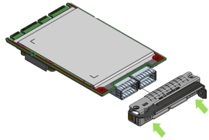
Assemble the new bracket onto the card.
Internal Lock Bracket
Pull-tab Bracket
Ejector-Latch Bracket


 Important
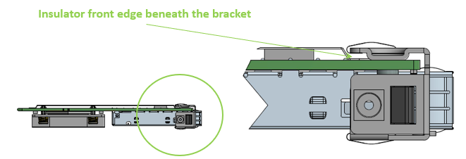
Do not force the bracket onto the adapter card.
Ensure that the insulator's front edge is beneath the bracket, as shown in the below figure.

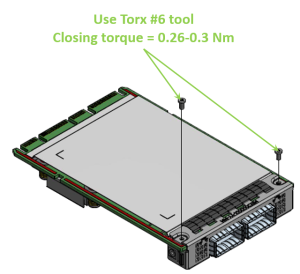
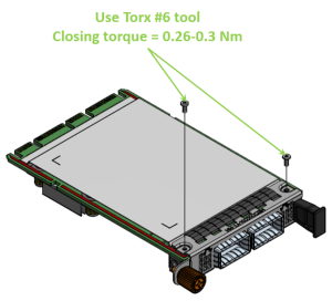
Screw on the OCP 3.0 bracket with the supplied screws that came with the new bracket kit. Use the specified torx tool type and apply the specified torque on the screws per bracket form factor.
Internal Lock Bracket
Pull-tab Bracket
Ejector-Latch Bracket


Note that one screw is flat-head 90° screw and the other is socket-head screw. Screw on the different types of screws as shown in the below illustration.

This section provides detailed instructions on how to install your adapter card in a system. The OCP 3.0 adapter card is shipped assembled either with an internal-lock, a pull-tab (thumbscrew), or an ejector-latch bracket. Follow the below instructions depending on the card you have purchased.
The following figures are for illustration purposes only.
Before installing the card, make sure that the system is off and the power cord is not connected to the server. Please follow proper electrical grounding procedures.
Open the system case.
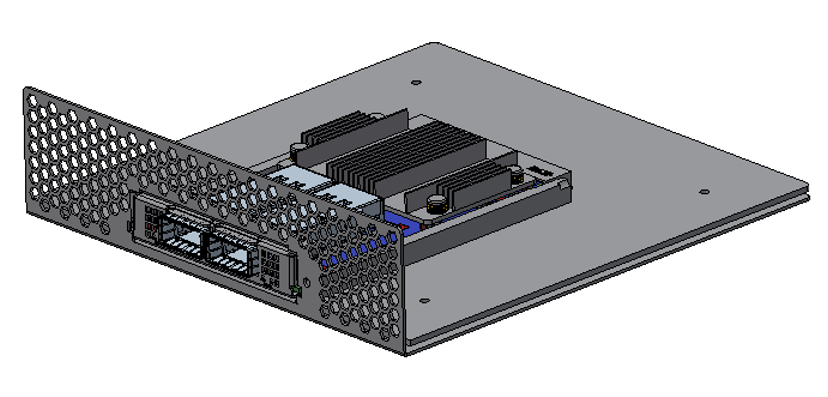
Align the card with the system rails.
Internal Lock Bracket
Pull-tab (Thumbscrew) Bracket
Ejector-Latch Bracket


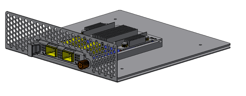
Push the card until connectors are in a full mate.
Internal Lock Bracket
Pull-tab (Thumbscrew) Bracket
Ejector-Latch Bracket


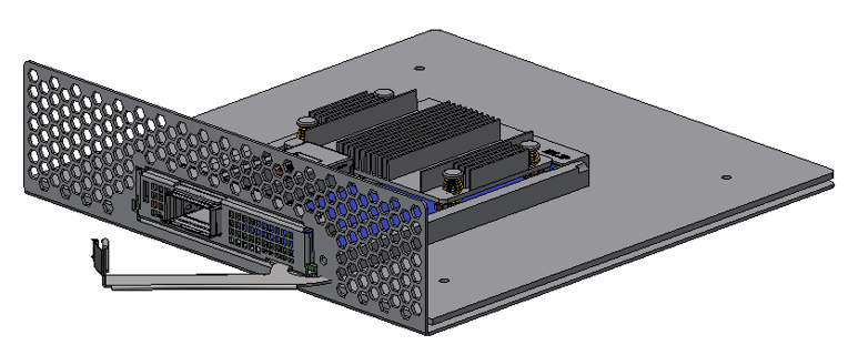
Secure the card.
Internal Lock Bracket
Pull-tab (Thumbscrew) Bracket
Ejector-Latch Bracket
A clicking sound is heardonce the connectors are in a full mate.
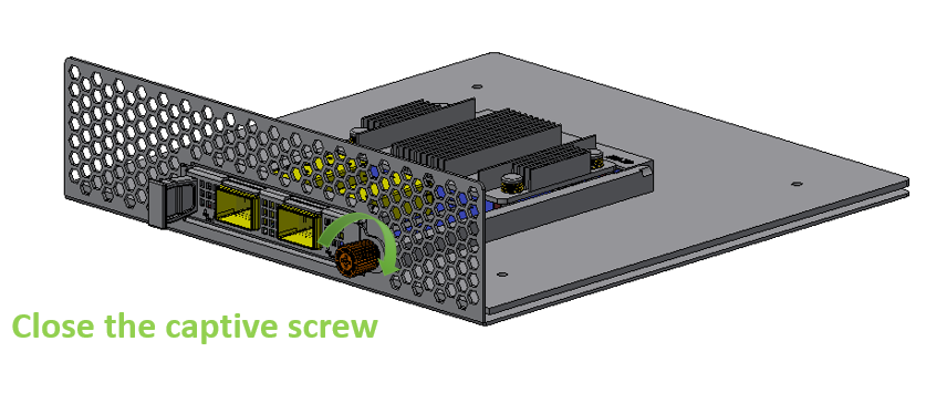
Turn the captive screw clockwise until firmly locked.

Close the ejector.

To uninstall the adapter card, see Uninstalling the Card.
Cable Installation
All cables can be inserted or removed with the unit powered on.
To insert a cable, press the connector into the port receptacle until the connector is firmly seated.
Support the weight of the cable before connecting the cable to the adapter card. Do this by using a cable holder or tying the cable to the rack.
Determine the correct orientation of the connector to the card before inserting the connector. Do not try and insert the connector upside down. This may damage the adapter card.
Insert the connector into the adapter card. Be careful to insert the connector straight into the cage. Do not apply any torque, up or down, to the connector cage in the adapter card.
Make sure that the connector locks in place.
WarningWhen installing cables make sure that the latches engage.
ImportantAlways install and remove cables by pushing or pulling the cable and connector in a straight line with the card.
After inserting a cable into a port, the Yellow or Green LED0 indicator will light when the physical connection is established (that is, when the unit is powered on and a cable is plugged into the port with the other end of the connector plugged into a functioning port). See Adapter Card LED Operations.
After plugging in a cable, lock the connector using the latching mechanism particular to the cable vendor. When a logical connection is made, Green LED1 will light. When data is being transferred, Green LED1 will blink.
Care should be taken as not to impede the air exhaust flow through the ventilation holes. Use cable lengths which allow for routing horizontally around to the side of the chassis before bending upward or downward in the rack.
To remove a cable, disengage the locks and slowly pull the connector away from the port receptacle. LED indicator will turn off when the cable is unseated.
On Linux
Get the device location on the PCI bus by running lspci and locating lines with the string “Mellanox Technologies”:
            lspci |grep -i Mellanox
Network controller: Mellanox Technologies MT28800 Family [ConnectX-5]
On Windows
Open Device Manager on the server. Click Start => Run, and then enter devmgmt.msc.
Expand System Devices and locate your NVIDIA ConnectX-5 adapter card.
Right click the mouse on your adapter's row and select Properties to display the adapter card properties window.
Click the Details tab and select Hardware Ids (Windows 2012/R2/2016) from the Property pull-down menu.
PCI Device (Example)

In the Value display box, check the fields VEN and DEV (fields are separated by ‘&’). In the display example above, notice the sub-string “PCI\VEN_15B3&DEV_1003”: VEN is equal to 0x15B3 – this is the Vendor ID of NVIDIA; and DEV is equal to 1018 (for ConnectX-5) – this is a valid NVIDIA PCI Device ID.
WarningIf the PCI device does not have a NVIDIA adapter ID, return to Step 2 to check another device.
WarningThe list of NVIDIA PCI Device IDs can be found at the PCI ID repository.
Follow the below instructions depending on the card form-factor you have purchased.
Safety Precautions
The adapter is installed in a system that operates with voltages that can be lethal. Before uninstalling the adapter card, please observe the following precautions to avoid injury and prevent damage to system components.
Remove any metallic objects from your hands and wrists.
It is strongly recommended to use an ESD strap or other antistatic devices.
Turn off the system and disconnect the power cord from the server.
Instructions
Please note that the following images are for illustration purposes only.
Verify that the system is powered off and unplugged.
Wait 30 seconds.
Unsecure the card.
Internal Lock Bracket
Pull-tab (Thumbscrew) Bracket
Ejector-Latch Bracket
While holding the heatsink, gently push the card out of the server.
 Important
Careful, the heatsink might be hot.
Rotate the captive screw counterclockwise.

Open the ejector latch.

Gently pull out the adapter card.
Internal Lock Bracket
Pull-tab (Thumbscrew) Bracket
Ejector-Latch Bracket
Gently pull out the adapter card from the server.

While holding the tab, pull out the adapter card.

Open the ejector latch.
