Interfaces
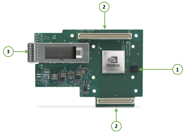
The below figures show the component side of the NVIDIA ConnectX-6 Dx adapter card. Each numbered interface that is referenced in the figures is described in the following table with a link to detailed information.
The ConnectX-6 Dx adapter card includes special circuits to protect from ESD shocks to the card/server when plugging copper cables
The below figures are for illustration purposes only and might not reflect the current revision of the adapter card.
NVIDIA ConenctX-6 Dx for OCP 2.0 Adapter Card Interfaces - Component Side
|
Callout |
Item |
Description |
|
1 |
NVIDIA ConnectX-6 Dx IC |
|
|
2 |
PCIe Gen 3.0/4.0 through an x16 edge connector. |
|
|
3 |
Ethernet traffic is transmitted through the adapter's SFP28/SFP56/QSFP56 connectors. The networking connectors allow for the use of modules, optical and passive cable interconnect solutions. |
|
|
There are two I/O LEDs, LED0 and LED1, per port to indicate speed and link status. |
||
|
FRU EEPROM capacity 4Kb |
||
|
Allows BMC connectivity using MCTP over SMBus or MCTP over PCIe protocols. |
||
|
Voltage supply pins that feed onboard regulators. |
||
|
Controls the networking port LEDs. |
The ConnectX®-6 Dx EN family of adapter IC devices delivers two ports of 10/25/40/50/100Gb/s or a single-port of 200Gb/s Ethernet connectivity paired with best-in-class hardware capabilities that accelerate and secure cloud and data-center workloads.
Encryption
Applies to Crypto-enabled OPNs.
ConnectX-6 Dx brings security to every end-point, including:
Purpose-built inline acceleration engines that offload IPsec and TLS data-in-motion and XTS-AES data-at-rest cryptographic operations.
Stateful firewall solution acceleration, powered by Open vSwitch connection tracking and NVIDIA’s ASAP2 technology.
Embedded hardware root-of-trust and support for RSA-based secure firmware update and secure boot, providing guaranteed integrity of the network adapter.
The network ports of the ConnectX®-6 Dx adapter card are compliant with the IEEE 802.3 Ethernet standards listed in Features and Benefits. Ethernet traffic is transmitted through the QSFP56 connectors on the adapter card.
The adapter card includes special circuits to protect from ESD shocks to the card/server when plugging copper cables.
The table below describes the supported PCIe interface in ConnectX®-6 Dx adapter cards.
|
Supported PCIe Interface |
Features |
|
PCIe Gen 3.0/4.0 (1.1 and 2.0 compatible) through x16 edge connectors |
Link Rates: 2.5. 5.0, 8.0 or 16GT/s. |
There are two I/O LEDs, LED0 and LED1, per port to indicate speed and link status. LED0 is bicolor (yellow and green) LED and LED1 is a single color (green) LED.
Link Indications
|
LED and State |
Description |
|||||||||
|
1Hz blinking Yellow |
Beacon command for locating the adapter card |
|||||||||
|
4Hz blinking Yellow |
Indicates an error with the link. The error can be one of the following:
|
|||||||||
|
LED0 - |
|
|||||||||
|
LED1 - |
|
FRU EEPROM
FRU EEPROM allows the baseboard to identify different types of Mezzanine cards. FRU EEPROM is accessible through SMCLK and SMDATA. FRU EEPROM address is defined according to SLOT_ID0 and SLOT_ID1 and its capacity is 4Kb.
ConnectX®-6 Dx technology maintains support for manageability through a BMC. ConnectX®-6 Dx OCP 2.0 adapter can be connected to a BMC using MCTP over SMBus or MCTP over PCIe protocols as if it is a standard NVIDIA OCP 2.0 adapter. For configuring the adapter for the specific manageability solution in use by the server, please contact NVIDIA Support.
The voltage regulator power is derived from the OCP 2.0 edge connector 12V and 3.3V supply pins. These voltage supply pins feed onboard regulators that provide the necessary power to the various components on the card.
The adapter card incorporates a CPLD device that controls the networking port LEDs and the scan chain. It draws its power supply from 3.3V_EDGE.