Hardware Installation
Installation and initialization of ConnectX-6 adapter cards require attention to the mechanical attributes, power specification, and precautions for electronic equipment.
Safety warnings are provided here in the English language. For safety warnings in other languages, refer to the Adapter Installation Safety Instructions.
Please observe all safety warnings to avoid injury and prevent damage to system components.
Note that not all warnings are relevant to all models.

| General Installation Instructions Read all installation instructions before connecting the equipment to the power source. |

| Jewelry Removal Warning Before you install or remove equipment that is connected to power lines, remove jewelry such as bracelets, necklaces, rings, watches, and so on. Metal objects heat up when connected to power and ground and can meltdown, causing serious burns and/or welding the metal object to the terminals. |
|
| Over-temperature This equipment should not be operated in an area with an ambient temperature exceeding the maximum recommended: 55°C (131°F). An airflow of 200LFM at this maximum ambient temperature is required for HCA cards and NICs. To guarantee proper airflow, allow at least 8cm (3 inches) of clearance around the ventilation openings. |
|
| During Lightning - Electrical Hazard During periods of lightning activity, do not work on the equipment or connect or disconnect cables. |
|
| Copper Cable Connecting/Disconnecting Some copper cables are heavy and not flexible, as such, they should be carefully attached to or detached from the connectors. Refer to the cable manufacturer for special warnings and instructions. |
|
| Equipment Installation This equipment should be installed, replaced, or serviced only by trained and qualified personnel. |
|
| Equipment Disposal The disposal of this equipment should be in accordance to all national laws and regulations. |
|
| Local and National Electrical Codes This equipment should be installed in compliance with local and national electrical codes. |

| Hazardous Radiation Exposure
|
The installation procedure of ConnectX-6 adapter cards involves the following steps:
Step | Procedure | Direct Link |
1 | Check the system’s hardware and software requirements. | |
2 | Pay attention to the airflow consideration within the host system | |
3 | Follow the safety precautions | |
4 | Unpack the package | |
5 | Follow the pre-installation checklist | |
6 | (Optional) Replace the full-height mounting bracket with the supplied short bracket | |
7 | Install the ConnectX-6 PCIe x16 adapter card in the system | |
Install the ConnectX-6 2x PCIe x16 Socket Direct adapter card in the system | ConnectX-6 Socket Direct (2x PCIe x16) Installation Instructions | |
8 | Connect cables or modules to the card | |
9 | Identify ConnectX-6 in the system |
Hardware Requirements
Unless otherwise specified, NVIDIA products are designed to work in an environmentally controlled data center with low levels of gaseous and dust (particulate) contamination.
The operating environment should meet severity level G1 as per ISA 71.04 for gaseous contamination and ISO 14644-1 class 8 for cleanliness level.
For proper operation and performance, please make sure to use a PCIe slot with a corresponding bus width and that can supply sufficient power to your card. Refer to the Specifications section of the manual for more power requirements.
ConnectX-6 Configuration | Hardware Requirements |
PCIe x16 | A system with a PCI Express x16 slot is required for installing the card. |
Socket Direct 2x PCIe x8 in a row (single slot) | A system with a custom PCI Express x16 slot (four special pins) is required for installing the card. |
Socket Direct 2x PCIe x16 (dual slots) | A system with two PCIe x16 slots is required for installing the cards. |
Airflow Requirements
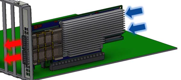
ConnectX-6 adapter cards are offered with two airflow patterns: from the heatsink to the network ports, and vice versa, as shown below.
Please refer to the Specifications section for airflow numbers for each specific card model.
Airflow from the heatsink to the network ports:
Airflow from the network ports to the heatsink:
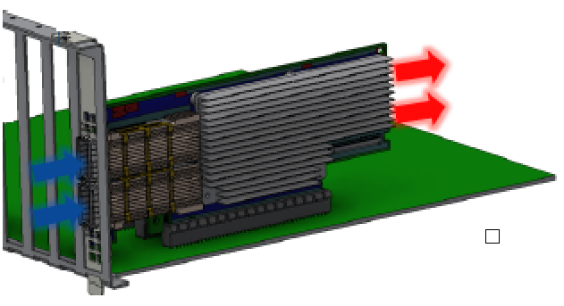
All cards in the system should be planned with the same airflow direction.
Software Requirements
See Operating Systems/Distributions section under the Introduction section.
Software Stacks - NVIDIA OpenFabric software package MLNX_OFED for Linux, WinOF-2 for Windows, and VMware. See the Driver Installation section.
The adapter is being installed in a system that operates with voltages that can be lethal. Before opening the case of the system, observe the following precautions to avoid injury and prevent damage to system components.
Remove any metallic objects from your hands and wrists.
Make sure to use only insulated tools.
Verify that the system is powered off and is unplugged.
It is strongly recommended to use an ESD strap or other antistatic devices.
Unpack the ConnectX-6 Card. Check against the Package Contents list that all the parts have been sent. Check the parts for visible damage that may have occurred during shipping. Please note that the cards must be placed on an antistatic surface.
WarningPlease note that if the card is removed hastily from the antistatic bag, the plastic ziplock may harm the EMI fingers on the networking connector. Carefully remove the card from the antistatic bag to avoid damaging the EMI fingers.
Shut down your system if active; Turn off the power to the system, and disconnect the power cord. Refer to the system documentation for instructions.
(Optional) Check the mounting bracket on the ConnectX-6 or PCIe Auxiliary Connection Card; If required for your system, replace the full-height mounting bracket that is shipped mounted on the card with the supplied low-profile bracket. Refer to Bracket Replacement Instructions.
The ConnectX-6 card and PCIe Auxiliary Connection card are usually shipped with an assembled high-profile bracket. If this form factor is suitable for your requirements, you can skip the remainder of this section and move to Installation Instructions. If you need to replace the high-profile bracket with the short bracket that is included in the shipping box, please follow the instructions in this section.
Due to risk of damaging the EMI gasket, it is not recommended to replace the bracket more than three times.
To replace the bracket you will need the following parts:
The new brackets of the proper height
The 2 screws saved from the removal of the bracket
Removing the Existing Bracket
Using a torque driver, remove the two screws holding the bracket in place.
Separate the bracket from the ConnectX-6 card.
WarningBe careful not to put stress on the LEDs on the adapter card.
Save the two screws.
Installing the New Bracket
Place the bracket onto the card until the screw holes line up.
WarningDo not force the bracket onto the adapter card.
Screw on the bracket using the screws saved from the bracket removal procedure above.
WarningUse a torque driver to apply up to 2 lbs-in torque on the screws.
This section provides detailed instructions on how to install your adapter card in a system.
Choose the installation instructions according to the ConnectX-6 configuration you have purchased.
OPNs | Installation Instructions |
MCX653105A-HDAT MCX653106A-HDAT MCX653105A-ECAT MCX653106A-ECAT MCX653105A-EFAT MCX653106A-EFAT | |
MCX654105A-HCAT MCX654106A-HCAT MCX654106A-ECAT |
Cable Installation
All cables can be inserted or removed with the unit powered on.
To insert a cable, press the connector into the port receptacle until the connector is firmly seated.
Support the weight of the cable before connecting the cable to the adapter card. Do this by using a cable holder or tying the cable to the rack.
Determine the correct orientation of the connector to the card before inserting the connector. Do not try and insert the connector upside down. This may damage the adapter card.
Insert the connector into the adapter card. Be careful to insert the connector straight into the cage. Do not apply any torque, up or down, to the connector cage in the adapter card.
Make sure that the connector locks in place.
NoteWhen installing cables make sure that the latches engage.
WarningAlways install and remove cables by pushing or pulling the cable and connector in a straight line with the card.
After inserting a cable into a port, the Green LED indicator will light when the physical connection is established (that is, when the unit is powered on and a cable is plugged into the port with the other end of the connector plugged into a functioning port). See LED Interface under the Interfaces section.
After plugging in a cable, lock the connector using the latching mechanism particular to the cable vendor. When data is being transferred the Green LED will blink. See LED Interface under the Interfaces section.
Care should be taken as not to impede the air exhaust flow through the ventilation holes. Use cable lengths which allow for routing horizontally around to the side of the chassis before bending upward or downward in the rack.
To remove a cable, disengage the locks and slowly pull the connector away from the port receptacle. LED indicator will turn off when the cable is unseated.
On Linux
Get the device location on the PCI bus by running lspci and locating lines with the string “Mellanox Technologies”:
ConnectX-6 Card Configuration | lspci Command Output Example |
Single-port Socket Direct Card (2x PCIe x16) |
|
Dual-port Socket Direct Card (2x PCIe x16) |
In the output example above, the first two rows indicate that one card is installed in a PCI slot with PCI Bus address 05 (hexadecimal), PCI Device number 00 and PCI Function number 0 and 1. The other card is installed in a PCI slot with PCI Bus address 82 (hexa-decimal), PCI Device number 00 and PCI Function number 0 and 1. Since the two PCIe cards are installed in two PCIe slots, each card gets a unique PCI Bus and Device number. Each of the PCIe x16 busses sees two network ports; in effect, the two physical ports of the ConnectX-6 Socket Direct adapter are viewed as four net devices by the system. |
Single-port PCIe x16 Card |
|
Dual-port PCIe x16 Card |
|
On Windows
Open Device Manager on the server. Click Start => Run, and then enter devmgmt.msc.
Expand System Devices and locate your NVIDIA ConnectX-6 adapter card.
Right click the mouse on your adapter's row and select Properties to display the adapter card properties window.
Click the Details tab and select Hardware Ids (Windows 2012/R2/2016) from the Property pull-down menu.
PCI Device (Example)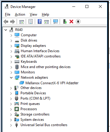
In the Value display box, check the fields VEN and DEV (fields are separated by ‘&’). In the display example above, notice the sub-string “PCI\VEN_15B3&DEV_1003”: VEN is equal to 0x15B3 – this is the Vendor ID of Mellanox Technologies; and DEV is equal to 1018 (for ConnectX-6) – this is a valid Mellanox Technologies PCI Device ID.
NoteThe PCI device does not have a NVIDIA adapter ID, return to Step 2 to check another device.
NoteThe list of PCI Device IDs can be found in the PCI ID repository.