Cards for Intel Liquid-Cooled Platforms Installation Instructions
The below instructions apply to ConnectX-6 cards designed for Intel liquid-cooled platforms with ASIC interposer cooling mechanism. OPNs: MCX653105A-HDAL and MCX653106A-HDAL.
The below figures are for illustration purposes only.
The below instructions should be used in conjunction with the server's documentation.
Please make sure the system is capable of supplying the required power as stated in Specifications.
Pay extra attention to the black bumpers located on the print side of the card. Failure to do so may harm the bumpers.

Apply the supplied thermal pad (one of the two) on top of the ASIC interposer or onto the coldplate.
The thermal pads are shipped with two protective liners covering the pad on both sides. It is highly important to peel the liners as instructed below prior to applying them to the card.
Gently peel the liner from the thermal pad's tacky side.
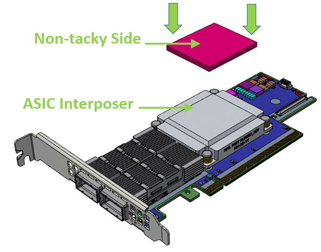
Carefully apply the thermal pad on the cool block (ASIC interposer) while ensuring it thoroughly covers it. Extra care should be taken not to damage the pad.
The thermal pad should be applied on the cool block from its tacky (wet) side. The pad should be applied with its non-tacky side facing up.
OR
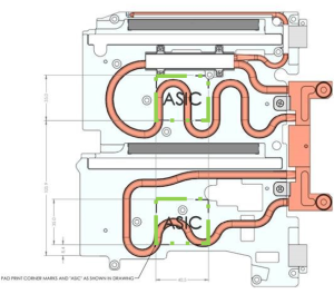
Carefully apply the thermal pad on the coldplate while ensuring it thoroughly covers it. The below figure indicates the position of the thermal pad. Extra care should be taken not to damage the pad.
The thermal pad should be applied on the coldplate from its tacky (wet) side. The pad should be applied with its non-tacky side facing up.
Ensure the thermal pad is in place and intact.
Once the thermal pad is applied to the ASIC interposer, the non-tacky side should be visible on the card's faceplate.
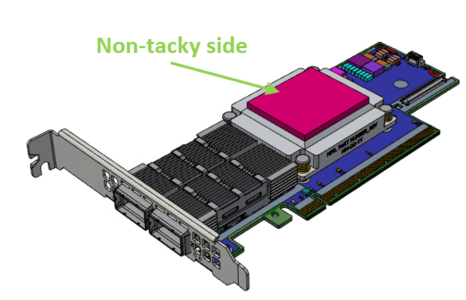
Gently peel the liner of the pad's non-tacky side visible on the card's faceplate. Failure to do so may degrade the thermal performance of the product.

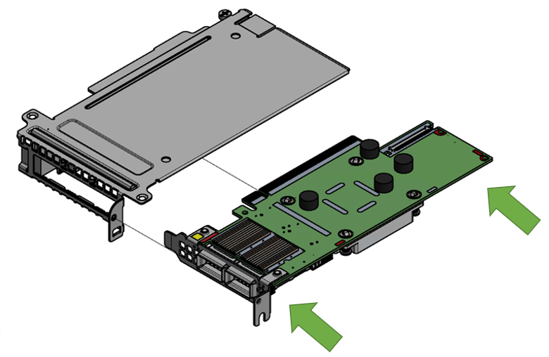
Install the adapter into the riser and attach the card to the PCIe x16 slot.
Disengage the adapter riser from the blade. Please refer to the blade documentation for instructions.
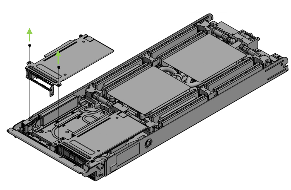
Applying even pressure at both corners of the card, insert the adapter card into the adapter riser until firmly seated. Care must be taken to not harm the black bumpers located on the print side of the card.
Vertically insert the riser that populates the adapter card into the server blade.

Applying even pressure on the riser, gently insert the riser into the server.
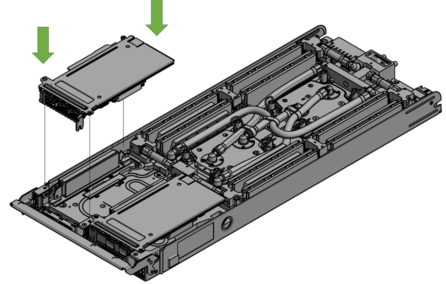
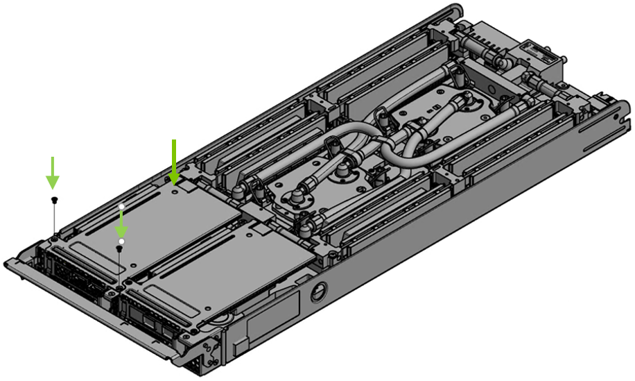
Secure the riser with the supplied screws. Please refer to the server blade documentation for more information.
