Specifications
Absolute maximum ratings are those beyond which damage to the device may occur.
Prolonged operation between the operational specifications and absolute maximum ratings is not intended and may cause permanent device degradation.
|
Parameter |
Min |
Max |
Units |
|
Supply voltage |
-0.3 |
3.6 |
V |
|
Data input voltage |
-0.5 |
3.9 |
V |
|
Control input voltage |
-0.3 |
3.9 |
V |
This table shows the environmental specifications for the product.
|
Parameter |
Min |
Max |
Units |
|
Storage temperature |
-10 |
70 |
°C |
This section shows the range of values for normal operation. The host board power supply filtering should be designed as recommended in the SFF Committee Spec.
|
Parameter |
Min |
Typ |
Max |
Units |
|
Supply voltage (Vcc) |
3.15 |
3.3 |
3.45 |
V |
|
Power consumption |
--- |
0.8 |
1 |
W |
|
Supply noise tolerance |
66 |
--- |
--- |
mV |
|
Power consumption |
--- |
0.8 |
1 |
W |
|
Supply noise tolerance |
66 |
--- |
--- |
mV |
|
Parameter (per lane) |
Min |
Typ |
Max |
Units |
|
Differential data input swing (TP1) |
190 |
--- |
700 |
mVpp |
|
Differential data output swing (TP4) |
300 |
--- |
850 |
mVpp |
|
Channel skew |
--- |
--- |
1.00 |
ns |
|
J2 Jitter Tolerance (TP1) |
0.17 |
--- |
-- |
UI |
|
J9 Jitter Tolerance (TP1) |
0.29 |
--- |
--- |
UI |
|
Data Dependent Pulse Width Shrinkage (DDPWS) |
--- |
--- |
0.11 |
UI |
|
Output transition time, 20% to 80% |
28 |
--- |
--- |
psec |
|
J2 Jitter Output (TP4) |
--- |
--- |
0.42 |
UI |
|
J9 Jitter Output (TP4) |
--- |
--- |
0.65 |
UI |
|
Parameter |
Value |
Units |
|
Diameter |
Option 1: 3.3mm; |
mm |
|
Minimum bend radius |
35 |
mm |
|
Length tolerance |
Length < 5m: +300mm /-0 |
m |
|
Cable color |
Length < 30m: (OM2) Orange |
|
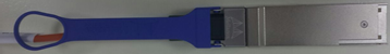
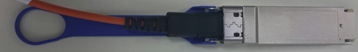
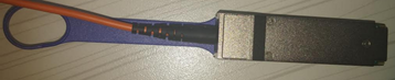
Backshell Options
The customer may receive cables with one of two backshell designs. The difference between the two designs is slight, as can be seen in the following table:
|
Backshell Design |
Cable Illustration |
|
|
Option 1 |
Front view |
|
|
Rear view |
|
|
|
Option 2 |
Front view |
|
|
Rear view |
|
|
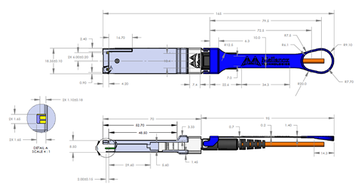
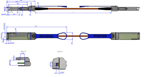
Mechanical Drawing
|
Option 1: |
|
|
Option 2: |
|
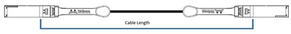
Length Measurement
|
Option 1: |
|
|
Option 2: |

|
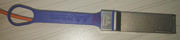
The following flag label is applied on the cable’s jacket.
Cable Flag Label
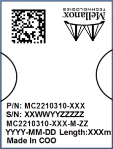
(sample illustration)
Images are for illustration purposes only. Product labels, colors, and lengths may vary.
Cable Jacket Flag Label Legend
|
Symbol |
Meaning |
Notes |
|
P/N Part Number |
||
|
XXX |
Length |
Meter |
|
S/N Serial Number |
||
|
XX |
Manufacturing site code |
2 characters MT |
|
WW |
Week of manufacturing |
2 digit |
|
YY |
Year of manufacturing |
2 digits |
|
ZZZZZ |
Serial number |
5 digits for serial number. Reset at start of week to 00001. |
|
Miscellaneous |
||
|
XXX |
Length |
Meter |
|
M |
Manufacturer code |
1 character |
|
ZZ |
Revision |
Hardware and software version |
|
YYYY-MM-DD |
Year-month-day |
Year 4 digits, month 2 digits, day 2 digits |
|
XXXm |
Length |
Meter |
|
COO |
Country of origin |
E.g. China or Malaysia |
|
Quick response code |
Barcode content: Part number Serial Number Revision |
|
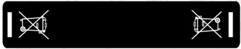
The following labels are applied on the cable’s jacket:
WEEE Cable Jacket Label
(sample illustration)
40G Cable Jacket Label

(sample illustration)
The laser module is classified as class I according to IEC 60825-1, IEC 60825-2 and 21 CFR 1040 (CDRH).
Safety: CB, cTUVus, CE
EMC: CE, FCC, ICES, RCM, VCCI
Ask your FAE for a zip file of the certifications for this product.
This equipment has been tested and found to comply with the limits for a Class A digital device, pursuant to part 15 of the FCC Rules. These limits are designed to provide reasonable protection against harmful interference when the equipment is operated in a commercial environment. This equipment generates, uses, and can radiate radio frequency energy and, if not installed and used in accordance with the instruction manual, may cause harmful interference to radio communications. Operation of this equipment in a residential area is likely to cause harmful interference in which case the user will be required to correct the interference at his own expense.