Specifications
Absolute maximum ratings are those beyond which damage to the device may occur.
Prolonged operation between the operational specifications and absolute maximum ratings is not intended and may cause permanent device degradation.
|
Parameter |
Min |
Max |
Units |
|
Supply voltage |
-0.3 |
3.6 |
V |
|
Data input voltage |
-0.3 |
3.465 |
V |
|
Control input voltage |
-0.3 |
4.0 |
V |
|
Damage Threshold |
3.4 |
--- |
dBm |
This table shows the environmental specifications for the product.
|
Parameter |
Min |
Max |
Units |
|
Storage temperature |
-40 |
85 |
°C |
This section shows the range of values for normal operation. The host board power supply filtering should be designed as recommended in the SFF Committee Spec.
|
Parameter |
Min |
Typ |
Max |
Units |
Notes |
|
Supply voltage (Vcc) |
3.135 |
3.3 |
3.465 |
V |
--- |
|
Power dissipation (each end, no retiming) |
--- |
1.5 |
1.8 |
W |
--- |
|
Power dissipation (each end, retiming on all lanes) |
--- |
2.2 |
2.5 |
W |
--- |
|
Supply noise tolerance (10 Hz – 10 MHz) |
66 |
--- |
--- |
mVpp |
--- |
|
Operating case temperature |
0 |
--- |
70 |
°C |
--- |
|
Operating relative humidity |
5 |
--- |
85 |
% |
--- |
|
Parameter (per lane) |
Min |
Typ |
Max |
Units |
|
Signaling rate |
-100 ppm |
25.78125 |
+100 ppm |
Gb/s |
|
Signaling rate (without retiming) |
0.3 |
25.784 |
Gb/s |
|
|
BER (Bit Error Rate)[1] |
--- |
--- |
10-15 |
--- |
|
Transmitter |
||||
|
Differential data input swing at TP1a |
According to IEEE 802.3bm |
--- |
900 |
mVpp |
|
Differential input return loss |
Meets equation (83E–5) in IEEE 802.3bm |
dB |
||
|
Receiver |
||||
|
Differential output return loss |
Meets equation (83E–5) in IEEE 802.3bm |
dB |
||
|
Differential data output swing at TP4 |
300 |
--- |
480 |
mVpp |
|
Common Mode output return loss |
--- |
--- |
-6 |
dB |
|
Output eye width (EW15) |
0.57 |
--- |
--- |
UI |
|
Output eye height (EH15) |
228 |
--- |
--- |
mV |
|
Output Transition time, 20 to 80% |
17 |
--- |
--- |
ps |
|
Output Eye Crossing |
45 |
--- |
--- |
% |
Notes:
[1] BER performance was verified with a PRBS31 test pattern in accordance with the IEEE 802.3bm specifications, as part of the product qualification.
[2] Requires optimization of the input equalizer.
For configurations tested with the AOCs please refer to the system level product quality assurance (SLPQA) report.
The transceiver has digital diagnostic monitoring (DDM) functions implemented in firmware version 32.20.124 and higher. The DDM functions are implemented according to SFF-8636 for reading the following key parameters with associated warning and alarm thresholds:
Temperature with warning/alarm
Supply voltage with warning/alarm
Laser bias current with warning/alarm
Transmitted optical power with warning/alarm
Received optical power with warning/alarm
|
Parameter |
Value |
Units |
|
Diameter |
3 +/-0.2 |
mm |
|
Minimum bend radius |
30 |
mm |
|
Length tolerance |
Length < 5 m: +300 /-0 |
mm |
|
Cable color |
Aqua |
--- |
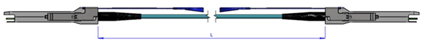
Mechanical Dimensions
Option 1:
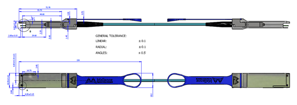
Cable Length Definition
Option 2:
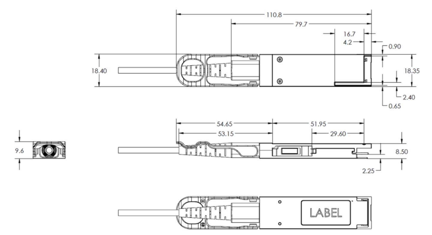
The following label is applied on the transceiver's back-shell:
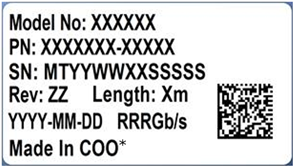
(sample illustration)
*COO – Country of Origin
Back-Shell Label SN (Serial Number) Legend
|
Symbol |
Meaning |
Notes |
|
MT |
Customer name (Mellanox/NVIDIA) |
2 digits (alphanumeric) |
|
YY |
Year of manufacturing |
2 digits (numeric) |
|
WW |
Week of manufacturing |
2 digit (numeric) |
|
XX |
Manufacturer site |
Two characters |
|
SSSSS |
Serial number |
5 digits (decimal numeric) for serial number, starting from 00001 |
The following label is applied on the cable’s jacket:
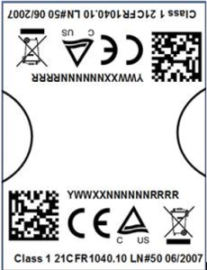
(sample illustration)
The laser module is classified as class I according to IEC 60825-1, IEC 60825-2 and 21 CFR 1040 (CDRH).
Safety: CB, cTUVus, CE
EMC: CE, FCC, ICES, RCM, VCCI
Ask your FAE for a zip file of the certifications for this product.
This equipment has been tested and found to comply with the limits for a Class A digital device, pursuant to part 15 of the FCC Rules. These limits are designed to provide reasonable protection against harmful interference when the equipment is operated in a commercial environment. This equipment generates, uses, and can radiate radio frequency energy and, if not installed and used in accordance with the instruction manual, may cause harmful interference to radio communications. Operation of this equipment in a residential area is likely to cause harmful interference in which case the user will be required to correct the interference at his own expense.