Pin Description
The SFP28 pin assignment is SFF-8419 compliant.
|
Pin |
Connector Pin Name |
Port A Signal Name |
|
1 |
VeeT |
Module Transmitter Ground |
|
2 |
Tx_Fault |
Module Transmitter Fault |
|
3 |
Tx_Disable |
Transmitter Disable. Turns off transmitter laser output |
|
4 |
SDA |
2-wire Serial Interface Data Line |
|
5 |
SCL |
2-wire Serial Interface Clock |
|
6 |
Mod_ABS |
Module Absent. Grounded within the module |
|
7 |
RS0 |
Rate Select 0, optionally controls SFP+ module receiver |
|
8 |
Rx_LOS |
Receiver Loss of Signal Indication |
|
9 |
RS1 |
Rate Select 1, optionally controls SFP+ module transmitter |
|
10 |
VeeR |
Module Receiver Ground |
|
11 |
VeeR |
Module Receiver Ground |
|
12 |
RD- |
Receiver Inverted Data Output |
|
13 |
RD+ |
Receiver Non-Inverted Data Output |
|
14 |
VeeR |
Module Receiver Ground |
|
15 |
VccR |
Module Receiver Power Supply |
|
16 |
VccT |
Module Transmitter Power Supply |
|
17 |
VeeT |
Module Transmitter Ground |
|
18 |
TD+ |
Transmitter Non-Inverted Data Input. AC coupled |
|
19 |
TD- |
Transmitter Inverted Data Input. AC coupled |
|
20 |
VeeT |
Module Transmitter Ground |
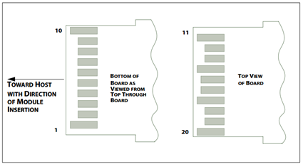
SFP28 Module Pad Layout
The transceiver’s management functions comply with SFF-8472.
Physical layer link tuning
Tx input equalization programmable in 11 levels up to 10 dB
Rx output pre-emphasis programmable in 8 levels up to 7 dB
Tx/Rx CDR control, refer to Appendix
DDM – Readout and Warning/Alarm Indication
Rx receive optical power monitor
Tx transmit optical power monitor
Tx bias current monitor
Module supply voltage monitor
Module case temperature monitor
MSA supported features and interrupt indications
Tx & Rx LOS
Tx & Rx LoL
Tx fault
Tx & Rx disable