Specifications
Absolute maximum ratings are those beyond which damage to the device may occur.
Prolonged operation between the operational specifications and absolute maximum ratings is not intended and may cause permanent device degradation.
Absolute Maximum Ratings
Parameter | Min | Max | Units |
Supply voltage | -0.3 | 3.6 | V |
Data input voltage | -0.3 | 3.465 | V |
Control input voltage | -0.3 | 4.0 | V |
Damage Threshold | 3.4 | --- | dBm |
Environmental Specifications
This table shows the environmental specifications for the product.
Parameter | Min | Max | Units |
Storage temperature | -40 | 85 | °C |
Operational Specifications
This section shows the range of values for normal operation. The host board power supply filtering should be designed as recommended in the SFF Committee Spec.
Parameter | Min | Typ | Max | Units | Notes |
Supply voltage (Vcc) | 3.135 | 3.3 | 3.465 | V | --- |
Power consumption 200Gb/s end | --- | 4.35 | 5.0 | W | --- |
Power consumption 400Gb/s end | --- | 9.0 | 10 | W | --- |
Supply noise tolerance (10Hz – 10MHz) | 66 | --- | --- | mVpp | --- |
Operating case temperature | 0 | --- | 70 | °C | --- |
Operating relative humidity | 5 | --- | 85 | % | --- |
Electrical Specifications
Parameter (per lane) | Min | Typ | Max | Units |
Signaling rate | -100 ppm | 26.5625 | +100 ppm | GBd |
Differential data input swing at TP1a | TBD | --- | 900 | mVpp |
Differential data output swing at TP4 | --- | --- | 900 | mVpp |
Near-end ESMW | 0.265 | --- | --- | UI |
Near-end output eye height | 70 | --- | --- | mVpp |
Output transition time, 20% to 80% | 9.5 | --- | --- | ps |
Notes:
- Multiple clock domains are supported only on line-side Rx.
- QSFP Tx CDR lock can only occur if Tx lane 4 is transmitting data.
Mechanical Specifications
Parameter | Value | Units | |
Diameter | 3 +/-0.2 | mm | |
Minimum bend radius | 30 | mm | |
Length tolerance | length < 5 m | +300 /-0 | mm |
5 m ≤ length < 50 m | +500 / -0 | ||
50 m ≤ length | +1000 /-0 | ||
Cable color | Aqua | --- | |
Cable Jacket | LSZH/OFNR | --- | |
Images are for illustration purposes only. Product labels, colors, and form may vary.
Shipped packages may vary in size, artwork, raw materials and other packaging elements.
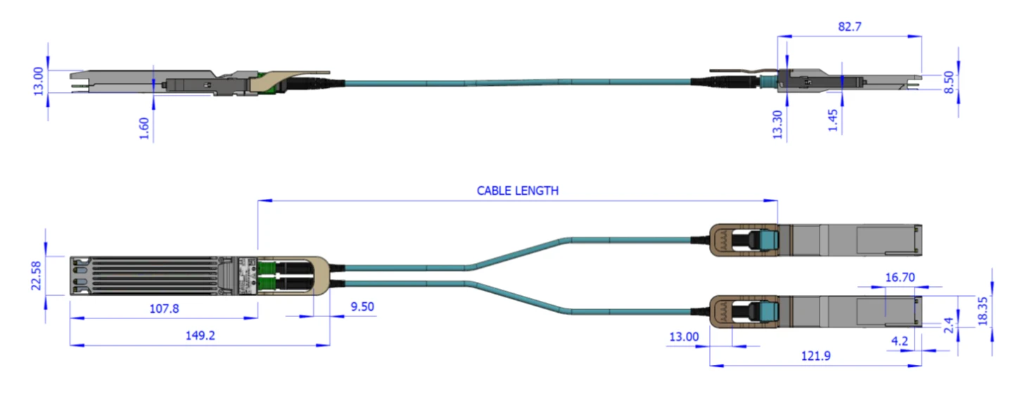
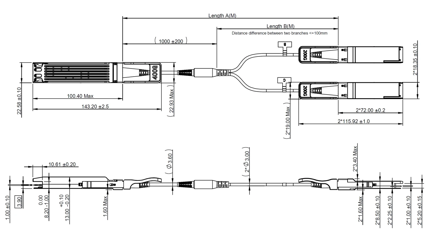
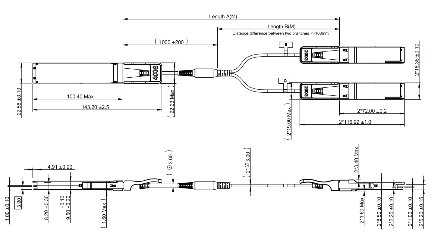
Mechanical Dimensions
Option 1
Option 2
Option 3
Connectivity Schematic
400Gb/s Side | 2x200Gb/s Side |
Port 1 | |
TX1 | RX1 |
RX1 | TX1 |
TX2 | RX2 |
RX2 | TX2 |
TX3 | RX3 |
RX3 | TX3 |
TX4 | RX4 |
RX4 | TX4 |
Port 2 | |
TX5 | RX1 |
RX5 | TX1 |
TX6 | RX2 |
RX6 | TX2 |
TX7 | RX3 |
RX7 | TX3 |
TX8 | RX4 |
RX8 | TX4 |
The following labels are applied on the AOC backshells:
400Gb/s Backshell Label
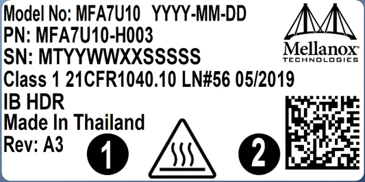
(sample illustration)
200Gb/s Backshell Label
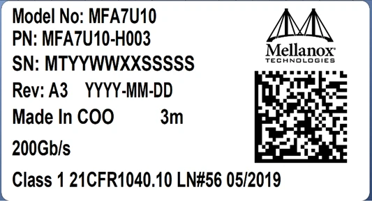
(sample illustration)
Backshell Label Legend
Symbol | Meaning | Notes | |
PN – Part Number | |||
xx | Length | Meter | |
SN – Serial Number | |||
MT | Manufacturer name | 2 characters, e.g. MT | |
YY | Year of manufacturing | 2 digits | |
WW | Week of manufacturing | 2 digits | |
XX | Manufacturer site | 2 characters | |
SSSSS | Serial number | 5 digits for serial number, starting from 00001. Reset at start of week to 00001. | |
Miscellaneous | |||
ZZ | HW and SW revision | 2 alpha-numeric characters | |
YYYY | Year of manufacturing | 4 digits | |
MM | Month of manufacturing | 2 digits | |
DD | Day of manufacturing | 2 digits | |
COO | Country of origin | E.g. China or Malaysia | |
XXm | Cable length | Meter | |

| Quick response code | Serial number (MTYYWWXXSSSSS) | |
The following label is applied on the cable’s jacket:
Fiber Cable Jacket Label

Note: The serial number and barcode are for NVIDIA internal use only.
Splitter Cable Labels Identifying the 2 QSFP56 Tails

The laser module is classified as class I according to IEC 60825-1, IEC 60825-2 and 21 CFR 1040 (CDRH).
Safety: CB, cTUVus, CE
EMC: CE, FCC, ICES, RCM, VCCI
Ask your NVIDIA FAE for a zip file of the certifications for this product.
This equipment has been tested and found to comply with the limits for a Class A digital device, pursuant to part 15 of the FCC Rules. These limits are designed to provide reasonable protection against harmful interference when the equipment is operated in a commercial environment. This equipment generates, uses, and can radiate radio frequency energy and, if not installed and used in accordance with the instruction manual, may cause harmful interference to radio communications. Operation of this equipment in a residential area is likely to cause harmful interference in which case the user will be required to correct the interference at his own expense.
The MFA7U10 is compatible with ESD levels in typical data center operating environments and certified in accordance with the standards listed in the Regulatory Compliance Section. The product is shipped with protective caps on its connectors to protect it until the time of installation. In normal handling and operation of high-speed cables and optical transceivers, ESD is of concern during insertion into the QSFP cage of the server/switch. Hence, standard ESD handling precautions must be observed. These include use of grounded wrist/shoe straps and ESD floor wherever a cable/transceiver is extracted/inserted. Electrostatic discharges to the exterior of the host equipment chassis after installation are subject to system level ESD requirements.